
Pen 1000 - Multimeter Testboy - Free user manual and instructions
Find the device manual for free Pen 1000 Testboy in PDF.


| Product Type | Universal probe multimeter |
| Brand | Testboy |
| Model | Pen 1000 |
| Category | Multimeter |
| Display | 5/6 digit backlit LCD display (max. 5999) |
| Voltage measurement ranges | DC/AC from 6V to 600V (True RMS, 50-800 Hz) |
| Resistance measurement ranges | 600Ω to 60MΩ |
| Capacitance measurement ranges | 10nF to 60mF |
| Frequency measurement ranges | 10Hz to 10MHz |
| Temperature measurement | -20°C to 50°C (1°C resolution) |
| Additional functions | Continuity test (threshold <50Ω), diode test, NCV detection, single-pole phase test, wireless rotating field test, flashlight, HOLD recording, relative measurement |
| Power supply | 1 AAA 1.5V battery |
| Battery life | Automatic shutdown after about 5 minutes |
| Measurement categories | CAT II 600V, CAT III 300V |
| Input impedance | 10 MΩ |
| Overload protection | 600V |
| Dimensions | 170 x 24 x 21 mm |
| Weight | Approximately 50 g |
| Maintenance | Clean with a slightly damp cloth and mild household cleaner; avoid harsh solvents |
| Battery replacement | AAA 1.5V battery; remove cables before replacement; observe polarity |
| Operating temperature | 0°C to 40°C |
| Storage temperature | 0°C to 40°C |
| Included accessories | Measuring cables, hanging clip |
Frequently Asked Questions - Pen 1000 Testboy
User questions about Pen 1000 Testboy
0 question about this device. Answer the ones you know or ask your own.
Ask a new question about this device
Download the instructions for your Multimeter in PDF format for free! Find your manual Pen 1000 - Testboy and take your electronic device back in hand. On this page are published all the documents necessary for the use of your device. Pen 1000 by Testboy.
USER MANUAL Pen 1000 Testboy
Testboy® Pen 1000
Version 1.1
de Testboy® Pen 1000 Bedienungsanleitung 3
en Testboy® Pen 1000 Operating instructions 17
fr Testboy® Pen 1000 Mode d'emploi 31
es Testboy® Pen 1000 Instrucciones de empleo 45
it Testboy® Pen 1000
Istruzioni per l'uso
59
Testboy® Pen 1000
Gebruiksaanwijzing
73
pl Testboy® Pen 1000
Instrukcja obsługi 87
SV Testboy® Pen 1000 Bruksanvisning 101
Hinweise
Sicherheitshinweise

WARNUNG
Sources of danger are, for example, mechanical parts that can cause serious injury to persons.
There is also a risk of damage to objects (e.g. damage to the appliance).
WARNING
Electric shock can result in death or serious injury to persons as well as endangering the function of objects (e.g. damage to the appliance).

WARNING
Never point the laser beam directly or indirectly at the eye through reflective surfaces. Laser radiation can cause irreparable damage to the eye. When measuring in the vicinity of people, the laser beam must be deactivated.
General safety instructions

WARNING
For safety and approval reasons (CE), unauthorised conversion and/or modification of the appliance is not permitted. To ensure safe operation of the appliance, you must observe the safety instructions, warning notices and the chapter "Intended use".

WARNING
Please observe the following instructions before using the appliance:
Avoid operating the appliance in the vicinity of electric welding equipment, induction heaters and other electromagnetic fields.
After abrupt temperature changes, the device must be adjusted to the new ambient temperature for approx. 30 minutes before use in order to stabilise the IR sensor.
Do not expose the appliance to high temperatures for long periods of time.
Avoid dusty and damp ambient conditions.
Measuring devices and accessories are not toys and do not belong in the hands of children!
In commercial facilities, the accident prevention regulations of the German Federation of Industrial Employers' Liability Insurance Associations for electrical systems and equipment must be observed.

Please observe the five safety rules:
1 Unlock
2 Secure against being switched on again
3 Check that there is no voltage (2 poles must be disconnected)
4 Earthing and short-circuiting
5 Cover neighbouring live parts
Intended use
The appliance is only intended for the applications described in the operating instructions. Any other use is not permitted and can lead to accidents or destruction of the appliance. Such use will immediately invalidate any guarantee and warranty claims the user may have against the manufacturer.

To protect the device from damage, please remove the batteries if the device is not to be used for an extended period of time.

We accept no liability for damage to property or personal injury caused by improper handling or non-compliance with the safety instructions. In such cases, all warranty claims are void. An exclamation mark in a triangle indicates safety instructions in the operating instructions. Read the instructions completely before using the appliance. This appliance is CE-approved and therefore fulfils the required directives.
Rights reserved to change specifications without prior notice.
© 2024 Testboy GmbH, Germany
Disclaimer

Damage caused by non-observance of the instructions will invalidate the warranty! We accept no liability for consequential damage resulting from this!
Testboy is not liable for damages resulting from
failure to observe the instructions,
modifications to the product not approved by Testboy or
spare parts not manufactured or approved by Testboy
are caused by the influence of alcohol, drugs or medication
result.
Correctness of the operating instructions
These operating instructions have been compiled with great care. No liability is accepted for the correctness and completeness of the data, illustrations and drawings. Changes, misprints and errors excepted.
Waste disposal
Dear Testboy-customer, when you purchase our product, you have the option of returning the device to suitable collection points for electronic waste at the end of its life cycle.

The WEEE regulates the take-back and recycling of waste electrical and electronic equipment. Manufacturers of electrical appliances are obliged to take back and recycle electrical appliances that are sold free of charge. Electrical appliances may then no longer be disposed of in the "normal" waste streams. Electrical appliances must be recycled and disposed of separately. All appliances that fall under this directive are labelled with this logo.
Disposal of used batteries

As the end user, you are legally obliged (Battery Act) to return all used batteries and rechargeable batteries; disposal with household waste is prohibited!
Batteries/rechargeable batteries containing hazardous substances are labelled with the adjacent symbols, which indicate that disposal with household waste is prohibited.
The designations for the decisive heavy metal are:
Cd = cadmium, Hg = mercury, Pb = lead.
You can return your used batteries/rechargeable batteries free of charge to the collection points in your municipality or wherever batteries/rechargeable batteries are sold!
Quality certificate
All within the Testboy GmbH are permanently monitored by a quality management system. The Testboy GmbH further confirms that the test equipment and instruments used during calibration are subject to permanent test equipment monitoring.
Declaration of Conformity
The product fulfils the latest directives. You can find more information at www.testboy.de
Operation
The Testboy® Pen 1000 is a universal pen multimeter. The measuring device is manufactured in accordance with current safety regulations and guarantees safe and reliable work. The multimeter is a valuable aid for all standard measuring tasks in the trade or industrial sector as well as for hobby electronics technicians. This meter is powered by a AAA 1.5V battery and uses a large backlit 5/6-digit LCD display.
On/Off
The meter switches on when the -button is pressed for longer than 2 seconds. To switch off, press the -button for longer than 2 seconds.
The device switches off automatically after approx. 5 minutes without a change in the measured value. (APO Auto-Power-off)
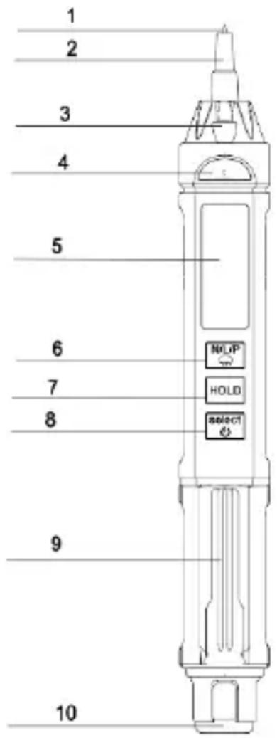
- Test probe tip: positive input of voltage, resistance, capacitance, frequency and phase sequence
- Input side test pin (protective cap)
- Torch
- Indicator display
- LCD display
- SELECT function selection button (long press for switching on/off, short press for manual DC or AC voltage/resistance/diode, buzzer measurement. Capacitance/frequency/temperature measurement)
- Measured value memory button
- Measuring the induction of an electric field/zero line Phase sequence measurement
- Hanging clip
- Negative input COM
Display
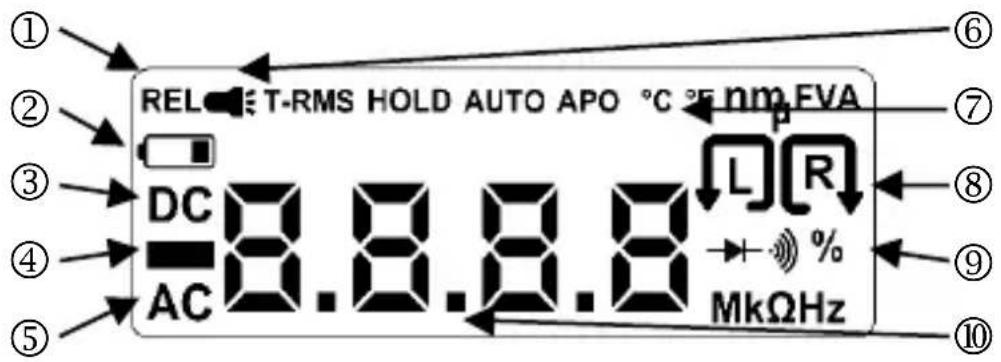
| 1 | Relative measurement | 2 | Battery symbol |
| 3 | DC voltage | 4 | Polarity sign |
| 5 | AC voltage | 6 | Torch |
| 7 | Temperature display (°C, °F) | 8 | Rotary field left / right |
| 9 | Continuity/diode test | 10 | Measured values |
Measured value memory button
When the button is pressed, the current measured value is saved and shown on the display.
Press the button again to return to the measuring function.
Torch
Press and hold the button to switch on the torch on the device; to switch it off, press and hold the button again.
DC/AC voltage test
The specific operation is as follows:
- Press and hold the - button for longer than 2 seconds to activate the "Auto" automatic measuring process.
- Plug the black measuring lead into the "COM" connection socket, the positive electrode is the tip of the device, this must be in firm contact with the measured point.
- If the measured voltage between the input connection "COM" and the "pin tip" is greater than 0.8V (regardless of whether DC or AC voltage), the measuring device compares the DC component and the AC component. It then takes the signal with the larger component and displays the corresponding measured value.
| Measuring range | Tolerance | Resolution |
| DC/AC 6V | ± (0.5%+4 digit) | 0.001V |
| DC/AC 60V | 0.01V | |
| DC 600V / AC 600V | 0.1V |
(input impedance 10MΩ; overload protection: 600V; true RMS measurement, frequency response 50Hz-800Hz)
Resistance measurement
| Measuring range | Tolerance | Resolution |
| 600Ω | ± (0.8%+5 digit) | 0.1Ω |
| 6kΩ | ± (0.8%+3 digit) | 1Ω |
| 60kΩ | 10Ω | |
| 600kΩ | 100Ω | |
| 6MΩ | 1kΩ | |
| 60M Ω | ± (2.5%+3 digit) | 10kΩ |
(input impedance 10MΩ; overload protection: 600V)
This measurement is carried out as follows:
- The automatic search mode "Auto" is shown on the display after switching on.
- Plug the black measuring lead into the "COM" connection socket, the positive electrode is the tip of the device, this must be in firm contact with the measured point.
- If the measured resistance at both ends of the test lead is less than 50Ω , the buzzer emits a continuous tone.
- If the voltage is greater than 0.8V, the meter will hold it for a voltage measurement and switch to voltage measurement mode.
- Connect the resistance to be measured between the "COM" and "pin tip" input terminals, the measuring device automatically switches between the 600Ω/6kΩ/60kΩ/600kΩ/6MΩ/60MΩ measuring ranges according to the measured resistance value, the measured value is displayed on the LCD.
Note:
- If you measure a low resistance, the test leads will have an internal resistance. To obtain accurate measured values, you can first record the short-circuit value of the test lead and subtract the value from the measured values.
- For the inline resistance measurement, all power supplies of the circuit to be tested must be switched off and all capacitors discharged.

Capacitance measurement
| Measuring range | Tolerance | Resolution |
| 10nF | ± (3.5%+20 digit) | 10pF |
| 100nF | 100pF | |
| 1uF | 1nF | |
| 10uF | 10nF | |
| 100uF | 100nF | |
| 1mF | 1uF | |
| 10mF | 10uF | |
| 60mF | ± (5%+3 digit) | 100uF |
(input impedance 10MΩ; overload protection: 600V)
- The automatic search status "Auto" is shown on the display.
- Plug the black measuring lead into the "COM" connection socket, the positive electrode is the tip of the device, this must be in firm contact with the measured point.
- If you want to carry out a quick continuity test/diode/capacitance measurement, you must press the button several times until you reach the capacitance measurement. During the measurement, the appropriate test range is automatically selected based on the size and the measured value is shown on the display. The capacitance measurement ranges are 10nF/100nF/1uF/10uF/100uF/1mF/10mF and 60mF
Note:

- When measuring capacitances in the range of 10nF, the values shown on the display may contain residual charge. This value is the distributed capacitance on the test leads and is an accurate measured value.
- If large capacitances, such as heavy leakage or breakdown capacitances, are measured, unstable values may be displayed. When measuring large capacitances, it takes a few seconds for the measured value to stabilise; this is normal when measuring large capacitances
- Please discharge capacitors completely before testing the capacitance, otherwise the device will switch to voltage mode.
- Units: 1F = 1000mF; 1mF = 1000uF; 1uF = 1000nF
NCV/LIVE/phase sequence measurement
The measuring process is started as follows:
- After the device has started up, it goes into the automatic scanning mode "Auto".
- Press the NUP - button to alternate between the electrical field measurement "EF", LIVE measurement "LIVE" and phase sequence measurement "PA" modes.
NCV measurement:
Press the -button once to access the electrical field measurement until the LCD display shows "EF". When the pen tip is close to the point to be tested (test frequency is 50Hz/60Hz), the display shows an increasing bar depending on the signal strength "----" is displayed. The buzzer increases the pitch depending on the signal strength. The indicator also changes colour, with a green light when the signal is weak and a red light when the signal is strong.
Single-pole phase test:
In AUTO mode, confirm the -button twice to access the live test and the display will show "LlvE". If the pen tip touches the live conductor, the LCD display shows "OL" and the buzzer beeps and the indicator lights up red at the same time.
Wireless rotating field test:
In AUTO mode, press the -button three times to access the phase sequence test. The display shows "PA".
Note:
- Shortly after selecting the test, "A" flashes. If the phase is recognised, "B" also flashes, record the second phase and finally the third phase "C".
- The shielded wire/cable and the thickness of the insulation material influence the measurement results. If the cable shielding influences the test, test nearby on an exposed connection.
- If the pin test probe is close to a test point, try to be vertically at only one phase, separate the phases as far apart as possible and do not cross several phase lines with each other, as this leads to mutual interference.

- Once all three phases have been recorded, the system analyses the data and shows it on the display:

"The symbol means rotating field left
"the symbol means rotating field right
- Please complete the three-phase sequence test within 1 minute, otherwise an error will occur; if an error occurs during the measurement, please press to repeat the test
Temperature measurement
| Measuring range | Tolerance | Triggering |
| (-20-50) °C | ± (1.0%+5 digit) <50°C | 1°C |
| (0-120) °F | ± (0.75%+5 digit) <122°F | 1°F |
- After switching on, the device is in "AUTO" scan mode.
- By pressing the select button several times, you can switch through the different modes as follows: Direct voltage (DC V) -> Alternating voltage (AC V) -> Capacitance measurement -> Diode test -> Temperature measurement (°C) -> Temperature measurement (°F) -> Frequency measurement (Hz) -> Auto
- Select the appropriate measurement method
- Only the room temperature is displayed.
Continuity test / diode test
Press the button four times to access the continuity test / diode test. Connect the black test lead to the "COM" socket at the end of the pin. The "pin tip" is the red test lead. Connect the test lead to the test circuit. The forward voltage is displayed during the diode test.
| Measuring range | Function |
 | The integrated buzzer signals passage be-low 50 Ω |
| Measuring range | Resolution | Display |
 | 1 mV | Forward voltage |
Frequency measurement
Press the -button seven times to access the frequency measurement. Connect the black test lead to the "COM" socket and the red test lead to the "pin tip". Connect the test leads to the test circuit and read the measurement result from the display.
| Measuring range | Resolution | Tolerance |
| 10 Hz | 0.001 Hz | ±(0.01 % + 5 digit) |
| 100 Hz | 0.01 kHz | |
| 1 kHz | 0.1 Hz | |
| 10 kHz | 1 Hz | |
| 100 kHz | 10 Hz | |
| 1 MHz | 100 Hz | |
| 10 MHz | 1 kHz |
(input impedance 10MΩ; overload protection: 600V)
Automatic switch-off (APO Auto-Power-OFF)
If the measuring device is not used for about 5 minutes, it switches off automatically and goes into standby mode. If you want to switch it on again, press and hold the button for longer than 2 seconds.
Troubleshooting
If your meter is not working normally, the following methods can help you to solve common problems quickly. If the fault still cannot be rectified, please contact the repair centre or dealer.
| The phenomenon of failure | Location and method of inspection |
| Display remains black | Battery too weak -> replace |
| Large resistance display error | Contact of the measuring line is not good or faulty |
Maintenance
The appliance does not require any special maintenance if it is operated in accordance with the operating instructions.
Cleaning
If the appliance has become dirty through daily use, it can be cleaned with a slightly damp cloth and a mild household cleaner. Never use harsh cleaning agents or solvents for cleaning.

WARNING
Make sure that no voltages above 600 V are applied to the test leads, even if the display allows this, as this could damage the electronics!
Battery change
The battery needs to be replaced when the battery symbol appears on the display. Before changing the battery, disconnect all measurement cables from the measurement object!
Only use batteries of the specified type.

Batteries do not belong in household waste. There is also a collection point near you!
Press in the small tab on the battery compartment and carefully open the flap upwards.
Ensure that the polarity of the batteries is correct! Replace the battery compartment cover and press it shut until the tab snaps back into place.
Definition of the measurement categories:
Measurement category II: Measurements on circuits that are electrically connected directly to the low-voltage grid via plugs. Typical short-circuit current < 10 kA
Measurement category III: Measurements within the building installation (stationary loads with non-pluggable connection, distribution board connection, permanently installed devices in the distribution board). Typical short-circuit current < 50 kA
Measurement category IV: Measurements at the source of the low-voltage installation (meter, main connection, primary overcurrent protection). Typical short-circuit current >> 50 kA
Technical data
The accuracy refers to 1 year at a temperature of +18 °C - +28 °C with a relative humidity of 75 %.
| Automatic measuring range selection | |
| Measurement categories | CAT II 600 VCAT III 300 V |
| Max. Operating height | 2000 m above sea level |
| Display | LCD |
| Display | 5/6 - Digit max. 5999 |
| Polarity indicator | automatically |
| Overflow indicator | "OL" is displayed |
| Sampling rate | 3 x per sec. |
| Battery status | Battery symbol is displayed |
| Automatic switch-off APO | after approx. 5 min. |
| Power supply | 1 x 1.5 V AAA Micro |
| Operating temperature | 0 °C to 40 °C |
| Storage temperature | 0 °C to 40 °C |
| Dimensions | 170 x 24 x 21mm |
| Weight | Approx. 50g |
Remarques
Cd = cadmium, Hg = mercure, Pb = plomb.
Cd = cadmium, Hg = kwik, Pb = lood.
Cd = kadmium, Hg = kvicksilver, Pb = bly.
Germany info@testboy.de

- Hinweise
- Sicherheitshinweise
- WARNUNG
- WARNING
- General safety instructions
- Intended use
- Disclaimer
- Correctness of the operating instructions
- Waste disposal
- Disposal of used batteries
- Quality certificate
- Declaration of Conformity
- Operation
- On/Off
- Display
- Measured value memory button
- Torch
- DC/AC voltage test
- Resistance measurement
- Note:
- Capacitance measurement
- NCV/LIVE/phase sequence measurement
- NCV measurement:
- Single-pole phase test:
- Wireless rotating field test:
- Continuity test / diode test
- Frequency measurement
- Automatic switch-off (APO Auto-Power-OFF)
- Troubleshooting
- Maintenance
- Cleaning
- Battery change
- Definition of the measurement categories:
- Technical data
- Remarques
Brand : Testboy
Model : Pen 1000
Category : Multimeter