TV435 - Multimeter Testboy - Free user manual and instructions
Find the device manual for free TV435 Testboy in PDF.


User questions about TV435 Testboy
0 question about this device. Answer the ones you know or ask your own.
Ask a new question about this device
Download the instructions for your Multimeter in PDF format for free! Find your manual TV435 - Testboy and take your electronic device back in hand. On this page are published all the documents necessary for the use of your device. TV435 by Testboy.
USER MANUAL TV435 Testboy
natural_image
Line drawing of a mechanical or electrical component with no visible text, numbers, or symbolsTestboy® TV435
Version 1.5
text_image
Diagram showing a power supply device connected to an iron iron, with labeled ports and digital display indicators.Abb. 3
Sources of danger include e.g. mechanical parts, which can cause serious injuries. Objects are also at risk (e.g. damage to the instrument).
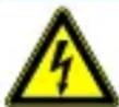
WARNING
An electric shock can result in death or serious injuries and endanger the function of objects (e.g. damage to the instrument).
General safety information

WARNING
Unauthorised modification and/or changes to the instrument are not permitted, for reasons of safety and approval (CE). In order to ensure safe and reliable operation of the instrument, you must always comply with the safety information, warnings and the information contained in the section “Intended use”.

WARNING
Observe the following information before using the instrument:
Avoid operating the instrument near to electric welding equipment, induction heaters or other electromagnetic fields.
To stabilise the instrument after abrupt changes in temperature, it must be allowed to adjust to the new ambient temperature for approx. 30 minutes before use.
Do not expose the instrument to high temperatures for a long period of time.
Avoid dusty and humid environments.
Measuring instruments and their accessories are not toys, and must be kept out of the reach of children!
When working in commercial facilities, comply at all times with the accident prevention regulations for electrical systems and equipment as established by the employer's liability insurance association.

Please observe the five safety rules:
1 Disconnect
2 Secure the instrument against reactivation
3 Ensure isolation from the power supply (check that there is no voltage on both poles)
4 Earth and short-circuit
5 Cover adjacent live parts
Intended use
The instrument is only intended for use in the applications described in the operating manual. Any other usage is forbidden, and can result in accidents or destruction of the instrument. Any such usage will result in the immediate voiding of all guarantee and warranty claims on the part of the operator against the manufacturer.

Remove the batteries if the instrument is not in use for a long period of time; this will protect the instrument against damage.

We shall not accept any liability for damage to property or injury to persons resulting from improper handling or non-compliance with the safety information. Any warranty claim will be voided in such cases. An exclamation mark in a triangle indicates safety information in the operating manual. Read the entire manual before commissioning. This instrument is CE-approved and thus fulfils the required directives.
We reserve the right to alter specifications without prior notice © 2020 Testboy GmbH, Germany.
Disclaimer

The warranty claim will be voided in cases of damage caused by failure to comply with the specifications of the manual! We shall not accept any liability for the resulting damage!
Testboy does not accept responsibility for damage resulting from:
Failure to comply with the specifications of the operating manual
Changes to the product which have not been approved by Testboy
The use of spare parts that have not been manufactured or approved by Testboy
The consumption of alcohol, drugs or medicines.
Accuracy of the operating manual
This operating manual has been compiled with considerable care and attention. No guarantee is given that the data, figures and drawings are complete or correct. Changes, printing mistakes and errors reserved.
Disposal
Dear Testboy customer, purchasing our product gives you the option of returning the instrument to suitable collection points for waste electrical equipment at the end of its lifespan.
The WEEE directive regulates the return and recycling of electrical appliances. Manufacturers of electrical appliances are obliged to take back and recycle all electrical appliances free of charge. Electrical devices may then no longer be disposed of through conventional waste disposal channels. Electrical appliances must be recycled and disposed of separately. All equipment subject to this directive is marked with this logo.
Disposal of used batteries
As an end user, you are legally obliged (battery law) to return all used batteries; disposal in the domestic waste is prohibited!
Batteries containing contaminant material are marked with this symbol indicating that they may not be disposed of in the domestic waste.
The abbreviations used for the crucial heavy metals are:
Cd = cadmium, Hg = mercury, Pb = lead.
You can return your used batteries free of charge to municipal collection points or anywhere where batteries are sold!
Certificate of quality
All quality-related activities and processes performed by Testboy GmbH are subject to continual monitoring within the framework of a Quality Management System. Testboy GmbH confirms that the testing equipment and instruments used during the calibration process are subject to a continual monitoring process.
Declaration of conformity
The product conforms to the most recent directives. For further information, go to www.testboy.de
Description of the instrument
The instrument has the following features:
• Separation of the leads into L, N and PE conductors for 2-pole and 3-pole cables
• Simple (L-N, L-PE, N-PE) AC voltage measurement with clamp meters/multimeters
- Simple AC current measurement with current clamp meters
- Current ring with x1 turn for direct current measurement
- Current ring with x10 turns for direct low current measurements
- Stray current measurement (leakage current measurement) directly at protective conductor
• Fault current measurement using differential measurement at L-N conductors
- Can be used for a load current of up to 16 A
text_image
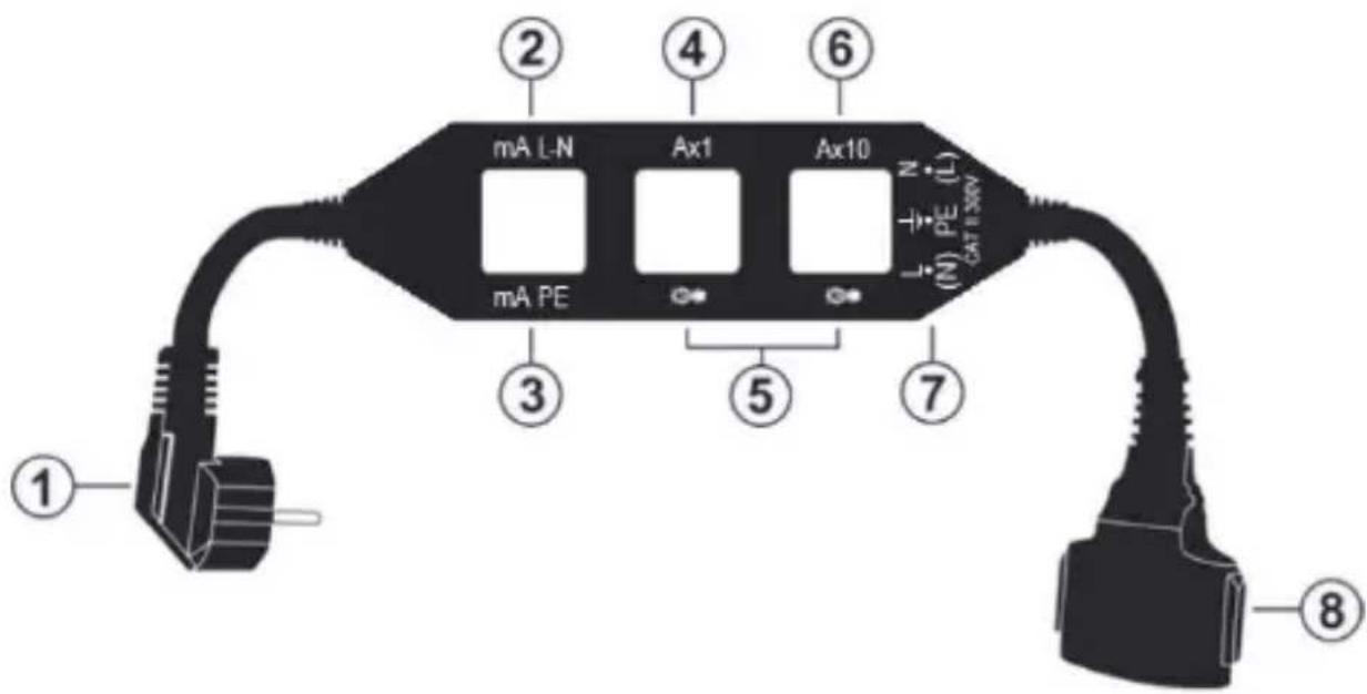
① ② ③ ④ ⑤ ⑥ mA L-N Ax1 Ax10 mA PE L ± N (N) PE (L) CAT 1.5kW ⑦ ⑧Fig. 1
- Earthed plug for connection to the socket
- Ring for differential current measurements between L-N conductors
- Ring for leak current measurements at PE conductor
-
Ring with x1 turn for current measurements
-
Not suitable for current measurements
- Ring with x10 turns for current measurements
- Test ports for L-N, L-PE and N-PE voltages
- Earthed socket for load connection (terminal device)
Function
The TV435 is a useful instrument that enables electrical separation between the active conductors of phase, neutral and PE for single-phase loads supplied with two or three-pole conductors with a current consumption of up to 16 A. The instrument enables immediate measurement directly at the conductors using clamp meters.
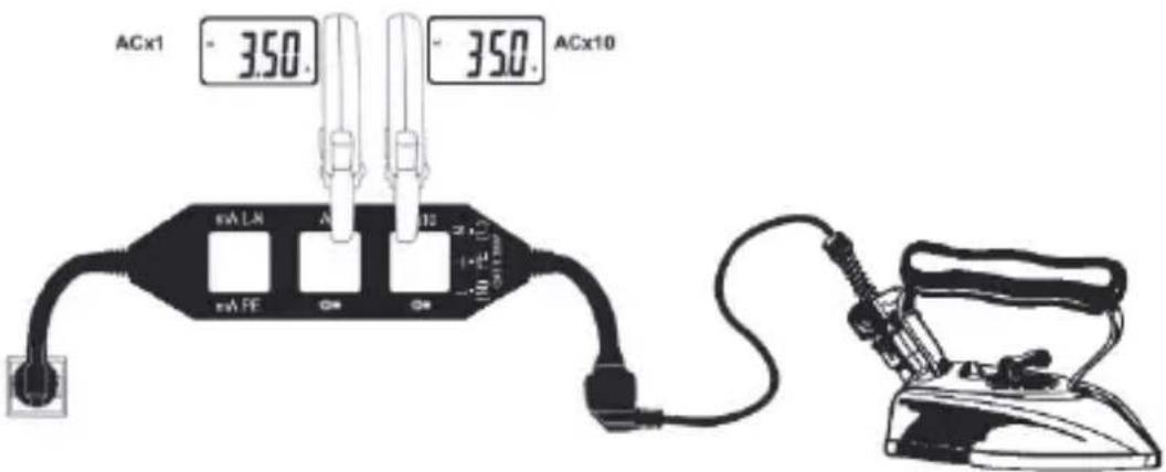
The TV435 has 2 rings (Ax1 and Ax10 - see Fig. 1, nos 4 and 6) to measure the line current, as well as this current multiplied by a factor of 10 (useful when using current clamp meters with a lower sensitivity or extremely high ranges).
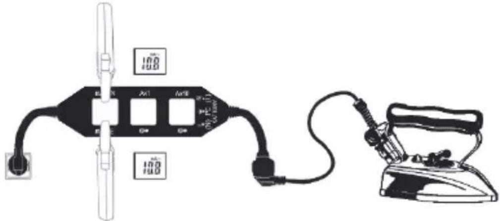
The instrument also has two additional rings (mA PE and mA L-N - see Fig. 1, nos 2 and 3) for simple measurement of the stray current, both direct and indirect/differential (on L-N conductors).
Finally, the TV435 also enables AC L-N, L-PE and N-PE voltage measurements to be carried out (see Fig. 1, no. 7) using multimeters.
Operation Load current measurement
- Connect the TV435 to the 230 V AC socket via the earthed plug.
- Connect the terminal device to the TV435 via the earthed plug.
- Guide the current clamp meter over the measuring points Ax1 or Ax10 and switch on the terminal device.
- Read off the line current values at ring Ax1 or divide the ring Ax10 reading by 10 (see Fig. 2).
text_image
ACx1 - 350. - 350. ACx10 mA LA A mA FE 10 10 L 10 L 10 L 10 L 10 L 10 L 10 L 10 L 10 L 10 L 10 L 10 L 10 L 10 L 10 L 10 L 10 L 10 L 10 L 10 L 10 L 10 L 10 L 10 L 10 L 10 M 10 M 10 M 10 M 10 M 10 M 10 M 10 M 10 M 10 M 10 M 10 M 10 M 10 M 10 M 10 M 10 M 10 M 10 M 10 M 10 M 10 M 10 M 10 M 10 M 10MFig. 2
Leakage current measurement
- Connect the TV435 to the 230 V AC socket via the earthed plug.
- Connect the terminal device to the TV435 via the earthed plug.
- Guide the current clamp meter over the measuring points mA PE or mA L-N and switch on the terminal device.
- Read off the direct stray current value (PE conductor) in the mA-PE ring or the indirect/differential stray current value (L-N conductor) in the mA-L-N ring (see Fig. 3).
text_image
Diagram showing a power supply circuit connected to an iron iron, with labeled components and digital display indicators.Fig. 3
Voltage and power measurement
- Connect the TV435 to the 230 V AC socket via the earthed plug.
- Connect the terminal device to the TV435 via the earthed plug.
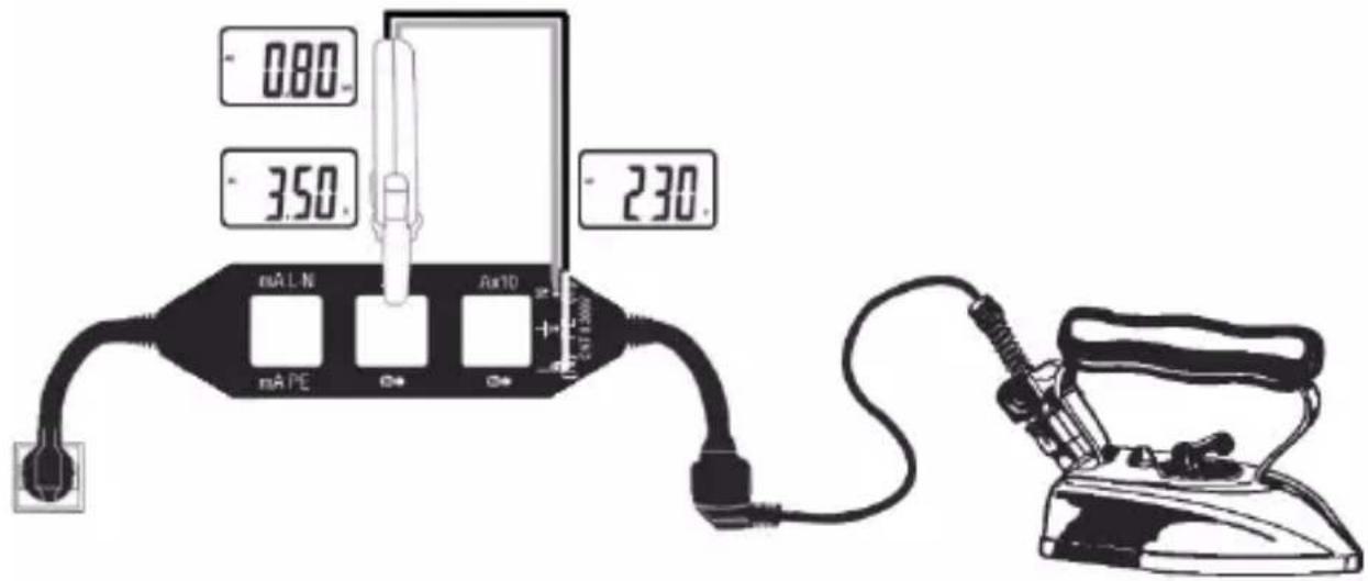
- Guide the current clamp meter over the measuring point Ax1 and the test leads at L and N, and switch on the terminal device.
- Read off the corresponding values for current, voltage and total input power of the load (see Fig. 4).
- Voltage measurements between the measuring points L-PE and N-PE are also possible.
text_image
0.80 3.50 2.30 mA L N mA PE Au10 + - 247-200V + - 200VFig. 4
Maintenance

WARNING
Maintenance work should always be performed by experienced and trained engineers. Disconnect all cables from the input connections before carrying out maintenance work.
Cleaning the instrument
Use a soft, dry cloth to clean the instrument. Never use a wet cloth, solvent, water, etc.
Technical data
| Energy supply | 110 - 240 V AC (+/- 10%) 50-60 Hz |
| Current connection | Integrated earthed plug, 30 cm length |
| Load connection | Integrated earthed socket, 30 cm length |
| Maximum load | 16 A |
| Operating temperature | -20 °C to +40 °C |
| Operating humidity | <80% RH |
| Storage temperature | -20 °C to +60 °C |
| Storage humidity | <80% RH |
| Safety standard | IEC/EN61010-1, IEC/EN61010-02-030 |
| Measurement category | CAT III 300 V |
| Maximum operating height | 2000 m |
| Dimensions | 17.5 cm x 5.3 cm x 1.5 cm |
| Weight | 307 g |
Consignes
Cd = Cadmium, Hg = mercure, Pb = plomb.
text_image
Diagram showing a digital timer connected to a power cord and a steam iron, both labeled with '100' values.Fig. 3
text_image
① ② ④ ⑥ mA L-N Ax1 Ax10 mA PE N (N) PE (L) CAT-3WV ③ ⑤ ⑦ ⑧Imagen 1
text_image
Diagram showing a power supply device connected to an iron iron, with labeled ports and digital display indicators.Imagen 3
© 2020 Testboy GmbH, Germania.
text_image
① ② ③ ④ ⑤ ⑥ ⑦ ⑧ mA L-N Ax1 Ax10 mA PE N (N) PE (L) CATE-WAYFig. 1
text_image
Diagram showing a power supply circuit connected to an iron, with digital display and connection points labeled.Fig. 3
Cd = cadmium, Hg = kwikzilver, Pb = lood.
text_image
Diagram showing a power supply device connected to an iron, with labeled terminals and digital display indicators.Afb. 3
Germany info@testboy.de