ST1401EST - Grass trimmer EGO - Free user manual and instructions
Find the device manual for free ST1401EST EGO in PDF.
| Product Type | Cordless String Trimmer |
| Brand | EGO |
| Model | ST1401EST |
| Rated Voltage | 56 V |
| No-load Speed (Low) | 3000 - 4500 rpm |
| No-load Speed (High) | 4000 - 5800 rpm |
| Cutting Mechanism | Bump Feed Head |
| Cutting Line Type | 2.4 mm Twisted Nylon Line |
| Cutting Width | 35 cm |
| Weight (without battery) | 5.8 kg |
| Guaranteed Sound Power Level | 91 dB(A) |
| Vibration Level (front handle) | 3.2 m/s² (K=1.5 m/s²) |
| Vibration Level (rear handle) | 2.3 m/s² (K=1.5 m/s²) |
| Operating Temperature | 0°C to 40°C |
| Storage Temperature | -20°C to 70°C |
| Optimal Charging Temperature | 5°C to 40°C |
| Compatible Battery | EGO 56 V Battery (not included) |
| Number of Speeds | 2 (low and high) |
| Safety | Lock-off lever, safety stop, eye and hearing protection required |
| Maintenance | Regular cleaning, sharpening cutting blade, store dry |
| Warranty | Manufacturer warranty (see EGO website) |
Frequently Asked Questions - ST1401EST EGO
User questions about ST1401EST EGO
0 question about this device. Answer the ones you know or ask your own.
Ask a new question about this device
Download the instructions for your Grass trimmer in PDF format for free! Find your manual ST1401EST - EGO and take your electronic device back in hand. On this page are published all the documents necessary for the use of your device. ST1401EST by EGO.
USER MANUAL ST1401EST EGO
natural_image
Technical line drawing of a mechanical device with no visible text or symbols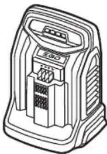
natural_image
Line drawing of a portable electronic device with ports and ventilation slots (no text or symbols)B1
natural_image
Diagram of a mechanical clamp or lever mechanism with directional arrows indicating motion (no text or symbols)
natural_image
Mechanical assembly diagram showing a bracket with two parts and an arrow indicating direction (no text or symbols)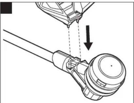
natural_image
Technical line drawing of a mechanical assembly with an arrow indicating a process (no text or symbols present)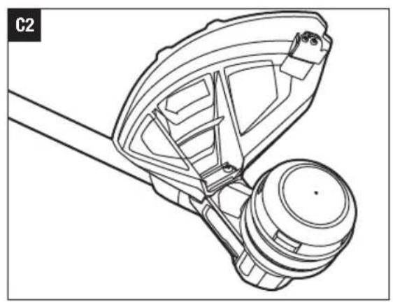
natural_image
Technical line drawing of a mechanical component with no visible text or symbols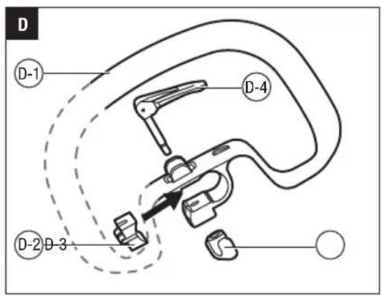
natural_image
Line drawing of a hand using a tool to lift a curved mechanical component (no text or symbols)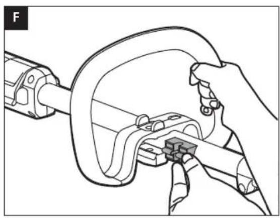
natural_image
Line drawing of a hand using a tool to adjust or install a mechanical component (no text or symbols present)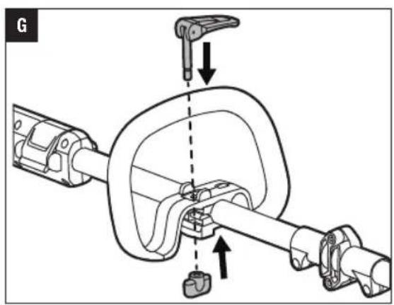
natural_image
Technical line drawing of a mechanical assembly with no visible text or symbols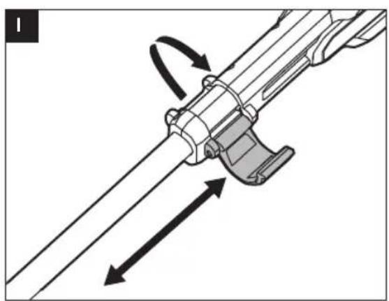
natural_image
Mechanical assembly diagram showing a lever mechanism with directional arrows indicating motion (no text or symbols)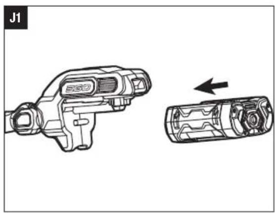
natural_image
Technical line drawing of a mechanical device (no text or symbols present)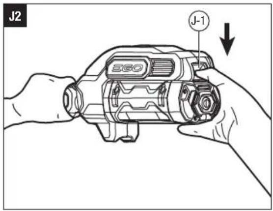
natural_image
Line drawing of a person in protective gear using a long-handled tool to clean grass (no text or symbols)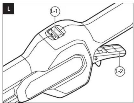
natural_image
Diagram of a mechanical device with downward arrows indicating flow or movement, surrounded by grass and ground (no text or symbols)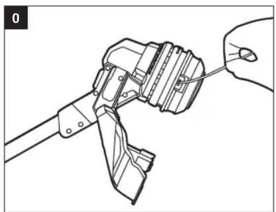
natural_image
Technical line drawing of a mechanical assembly with a hand holding a tool (no text or symbols present)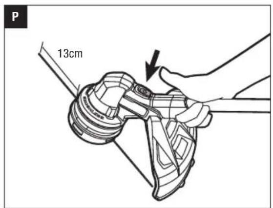
natural_image
Technical line drawing of a mechanical clutch assembly (no text or symbols)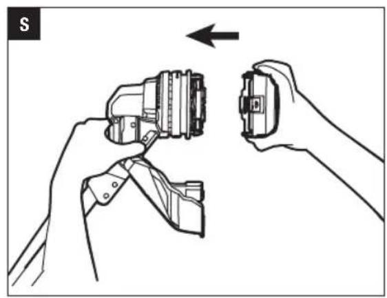
natural_image
Illustration of hands holding a connector with an arrow indicating direction (no text or symbols)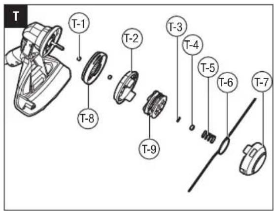
natural_image
Technical line drawing of a mechanical assembly with no visible text or symbols
natural_image
Illustration showing a hand using a power tool to adjust a component, with no visible text or symbols.EN READ ALL INSTRUCTIONS!

READ OPERATOR'S MANUAL
Residual risk! People with electronic devices, such as pacemakers, should consult their physician(s) before using this product. Operation of electrical equipment in close proximity to a heart pacemaker could cause interference or failure of the pacemaker.
SAFETY SYMBOL
The operation of any power tools can result in foreign objects being thrown into your eyes, which can result in severe eye damage. Before beginning power tool operation, always wear safety goggles or safety glasses with side shields and a full face shield when needed. We recommend a Wide Vision Safety Mask for use over eyeglasses or standard safety glasses with side shields.

Safety Alert

Wear Eye Protection-Always wear safety goggles or safety glasses with side shields and a full face shield when operating this product.

Wear Ear Protection-Always wear ear protection when operating this product.

Wear Head Protection-Wear an approved safety hard hat to protect your head.

Do not install round cutting blades.

Cutting width-The Max. cutting width of line trimmer

Ensure that other people and pets remain at least 15m away from the line trimmer when it is in use.

Guaranteed sound power level. Noise emission to the environment according to the European community's Directive.
Waste electrical products should not be disposed of with household waste. Take to an authorized recycler.

To reduce the risk of injury, user must read the operator's manual.

Wear Safety Footwear-Wear non-slip safety footwear when using this equipment.

Wear Protective Gloves-Protect your hands with gloves when handling blade or blade guard.

Beware of blade thrust-Warm the operator of the danger of blade thrust.

Line diameter-The Diameter of the nylon cutting line
Thrown objects can ricochet and result in personal injury or property damage. Ensure that other people and pets remain away from the brush cutter when it is in use.

Do not use in the rain or leave outdoors while it is raining.

This product is in accordance with applicable EC directives.
V Voltage
n_0
No Load Speed-Rotational speed, at no load .../min Per Minute
三
Direct Current kg Kilogram
SPECIFICATIONS
| Voltage | 56 V --- | |
| No-load Speed | Low speed set:3000-4500 RPMHigh speed set:4000-5800RPM | |
| Cutting Mechanism Bump Head | ||
| Cutting Line Type | 2.4mmnylon twist line | |
| Cutting Width 35 cm | ||
| Recommended Operating Temperature | 0°C-40°C | |
| Recommended Storage Temperature | -20°C-70°C | |
| Optimum Charging Temperature 5°C-40°C | ||
| Weight (without battery pack) 5.8 kg | ||
| Measured sound power level L_WA | 88.98 dB(A)K=2 dB(A) | |
| Sound pressure level at operator's ear L_PA | 68.96 dB(A)K=2 dB(A) | |
| Guaranteed sound power level L_WA (measured according to 2000/14/EC) | 91 dB(A) | |
| Valuation of vibration a_h | Front-assist handle | 3.2 m/ s^2 K=1.5 m/ s^2 |
| Rear handle | 2.3 m/ s^2 K=1.5 m/ s^2 | |
■ The declared vibration total value has been measured nin accordance with a standard test method and may be used for comparing one tool with another;
■ The declared vibration total value may also be used in a preliminary assessment of exposure.
NOTICE: The vibration emission during actual use of the power tool can differ from the declared value in which the tool is used; In order to protect the operator, user should wear gloves and ear protectors in the actual conditions of use.
DESCRIPTION
KNOW YOUR LINE TRIMMER (Fig. A1)
- Rear Handle
- High/Low Speed Switch
- Adjustable Front-Assist Handle
- Hinge
-
Line-Loading Button
-
Guard
- Lock Pole
- Height Locking Collar
- Switch Trigger
- Locking Tongue
- Trimmer Head (Bump Head)
- Line Cutting Blade
- Release Tab
- Cutting Line
- Battery Release Button
- Latch
- Electric Contacts
- Ejection Mechanism
- Hex Wrench
PACKING LIST (FIG.A1)
ASSEMBLY
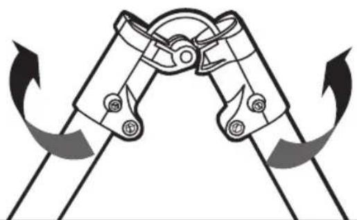
UNFOLDING THE SHAFT
WARNING: Do not hold the shaft at the joints in order to avoid pinching your hands or fingers.
WARNING: Do not attempt to start the trimmer until the shaft has been locked.
Unfold the shaft gently, ensuring the cable inside the shaft, and lock it with two screws by the supplied wrench (Fig. B1 & B2).
MOUNTING THE GUARD
Position your trimmer so that the trimmer head faces up (Fig. C1). Align the guard mounting holes with the assembly holes and then lock the guard onto the shaft base with the two screws (Fig. C2).
NOTICE: Make sure the guard is fixed according to Fig. C1 & C2, any reverse fixing will cause great danger!
MOUNTING AND ADJUSTING THE FRONT-ASSIST HANDLE
- Loosen the locking pole in the front-assist handle and remove the locking pole and wing nut form the front-assist handle (Fig. D).
| D-1 | Front-assist handle | D-3 | Wing nut |
| D-2 | Clamping block | D-4 | Locking pole |
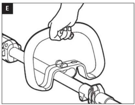
- Push the front assist-handle onto the shaft between the Height Locking Collar and hinge (Fig. E).
- Insert the clamping block into the handle slot (Fig. F).
- Mount the locking pole lever and pre-tighten the wing nut. Make sure that the front-assist handle is positioned upwards and points toward the top of the rear handle (Fig. J).
EN
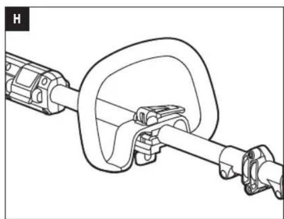
- Pull up the level of the lock pole so that you can easily move/rotate the loop handle to where you feel comfortable. then lock the lever of the locking pole. (Fig. H).
WARNING: The tool cannot be used without the front handle securely fixed.
ADJUSTING THE REAR HANDLE
If the length of the shaft is not suitable for operation, you can adjust the length of the shaft through this Height Locking clamp.
- Remove the battery pack from the trimmer.
- To adjust the trimmer height, open the height locking clamp, and then slide the shaft up or down to desired height, securing it in place by depressing the locking clamp (Fig. I).
NOTICE: The front assist-handle may require to be readjusted after the trimmer height is changed.
OPERATION
WARNING: Always wear safety goggles or safety glasses with side shield, along with hearing protection. Failure to do so could result in objects being thrown into your eyes and other possible serious injuries.
You may use this product for the purposes listed below:
Trimming: Used for removing grass and weeds up against walls, fences, trees and borders.
Cutting: Used for cutting the grass that is difficult to reach using a normal mower.
ATTACHING/DETACHING THE BATTERY PACK
Use only with EGO's battery packs and chargers listed in Fig. A2.
Fully charge before first use.
To Attach
Align the battery ribs with the mounting slots and press the battery pack down until you hear a "click" (Fig. J1).
To Detach
Depress the battery-release button and pull the battery pack out as Fig. J2 shown.
J-1 Battery- Release button
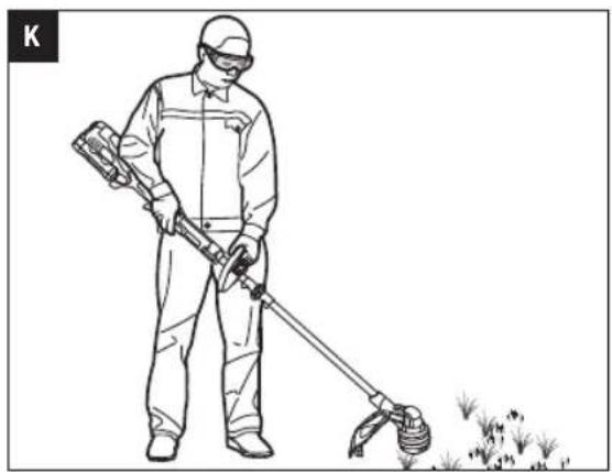
HOLDING THE LINE TRIMMER
Hold the line trimmer with both hands: One hand on the rear handle and the other hand on the front-assist handle.
NOTICE: The trimmer head is parallel to the ground at a proper cutting distance without the operator bending over (Fig. K).
STARTING/STOPPING THE LINE TRIMMER
To Start
Move the locking tongue forwards then depress the switch trigger.
The trigger is stepless speed adjusting. The more you pull up the trigger, the higher speed it is (Fig. L).
To Stop
Release the switch trigger.
SPEED ADJUSTMENT FUNCTION (FIG. L)
The line trimmer has two speeds. Position "LOW" is for low speed while Position "HIGH" for high speed.
Fig. L parts description see below:
L-1 High/low-Speed Switch L-2 Switch Trigger
USING THE LINE TRIMMER
Clear the area to be cut before each use. Remove all objects, such as rocks, broken glass, nails, wire, or line that can be thrown or become entangled in the cutting attachment. Clear the area of children, bystanders, and pets. At a minimum, keep all children, bystanders and pets at least 15m away; there still may be risk to bystanders from thrown objects. Bystanders should be encouraged to wear eye protection. If you are approached, stop the motor and cutting attachment immediately.
Before each use, check for damage/worn parts
Check the bump head, guard and front-assist handle and replace the parts that are cracked, warped, bent, or damaged in any away.
The line-cutting blade on the edge of the guard can dull over time. It is recommended that you periodically sharpen it with a file or replace it with a new blade.
After each use, clean the trimmer.
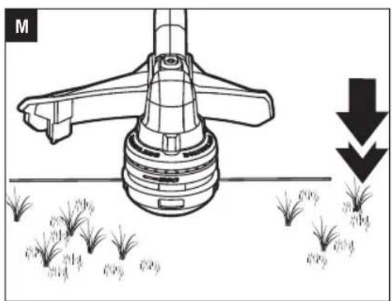
ADJUSTING CUTTING LINE LENGTH
The trimmer head allows the operator to release more cutting line without stopping the motor. As line becomes frayed or worn, additional line can be released by lightly tapping the trimmer head on the ground while operating the trimmer (Fig. M).
NOTICE: Line release will require multiple tapping as the cutting line becomes shorter.
WARNING: Do not remove or alter the line cutting blade assembly. Excessive line length will cause the motor to overheat and may result in serious personal injury.
LINE REPLACEMENT
NOTICE: Always use the recommended nylon cutting line with a diameter that does not exceed 2.4 mm. Using line other than that specified may cause the line trimmer to overheat or become damaged.
WARNING: Never use metal-reinforced line, wire, or rope, etc. These can break off and become dangerous projectiles.
- Remove the battery pack.
- Remove the remaining cutting line, if necessary.
- Cut 4 m of cutting line. Insert the line into the mounting hole inside the eyelet (Fig. 0). Push and pull the line from the other side until equal amounts of line appear on both sides of the spool.
- Install the battery pack onto the string trimmer.
- Press and hold the line-loading button to start the line-winding motor. The line will be wound into the trimmer head continuously (Fig. P).
- Watch the remaining line length carefully. Briefly press the line loading button to adjust the length until 13 cm of the line is showing on each side.
- Push down on the trimmer head while pulling on the lines to manually advance the line in order to check for proper assembly of the cutting line.
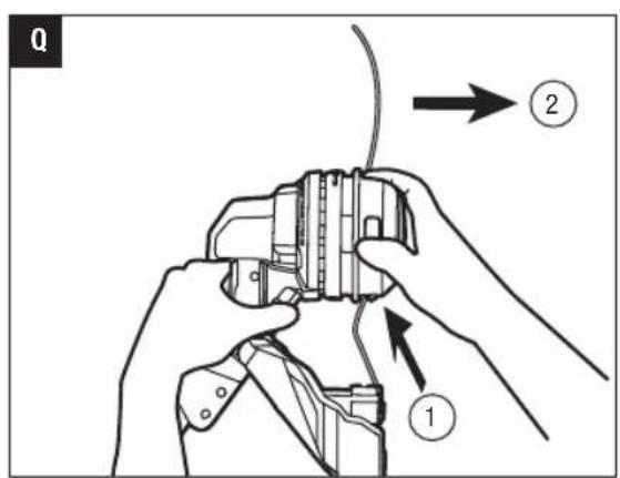
When the cutting line breaks from the line outlet or the cutting line is not released when the trimmer head is tapped, follow the steps below
- Remove the battery pack from the trimmer.
- Press the release tabs on the trimmer head and remove the lower cover assembly by pulling it straight out (Fig. Q).
- Remove the cutting line from the spool.
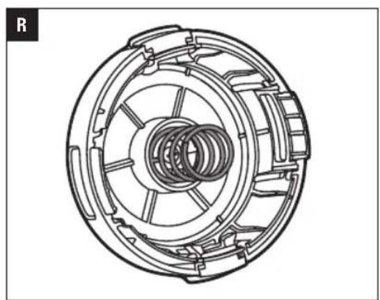
- Insert the spring into the slot in the lower cover assembly (Fig. R).
-
With one hand holding the trimmer, use another hand to grasp the lower cover assembly and align the slots in the lower cover assembly with the release tabs. Press the lower cover assembly until it snaps into place, at which time you will hear a distinct click sound (Fig. S).
-
Follow the instructions in the "LINE REPLACEMENT" section to reload the cutting line.
TRIMMER HEAD REPLACEMENT
WARNING: If the head loosens after it is fixed in position, replace it immediately. Never use a trimmer with a loose cutting attachment. Replace a cracked, damaged or worn out cutting head immediately, even if damage is limited to superficial cracks. Such attachments may shatter at high speed and cause serious injury.
REMOVE THE TRIMMER HEAD
- Remove the battery pack from the trimmer.
- Press the release tabs on the trimmer head and remove the lower cover assembly of the trimmer head by pulling it straight out.
- Remove the cutting line from the trimmer head (Fig. S).
- Take the spring out of the spool assembly, if necessary. Save it for reassembly.
- Wear gloves. Use one hand to grasp the spool assembly to stabilize it, and use the other hand to hold an impact wrench (not included) to loosen the nut in a counterclockwise direction (Fig. X).
- Remove the nut, spool retainer, upper cover, upper base cover, from the motor shaft (Fig. T).
NOTICE: Two bushings easily fall off the motor shaft, pleas save them carefully for reassembly.
- Replace with a new trimmer head and mount it in following steps.
| T-1 Bushing T-6 Trimmer Line |
| T-2 Upper Cover T-7 Lower Cover |
| T-3 Nut T-8 Upper base cover |
| T-4 Washer T-9 Assembly Spool Assembly |
| T-5 Spring |
INSTALL THE NEW TRIMMER HEAD
- Mount the bushings in motor shaft and mount the upper base cover assembly into place (Fig. T).
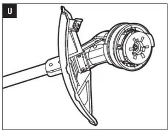
- Mount the upper cover, spool assembly, washer and nut in that order. Use an impact wrench on the nut to tighten it (Fig. U & V).
- Mount the lower cover assembly.
- Reload the cutting line.
- Start the tool to see whether the string trimmer will work normally. If it does not, reassemble as described above.
EN MAINTENANCE
WARNING: When servicing, use only identical replacement parts. Inspect and maintain the machine regularly. To ensure safety and reliability, all repairs should be performed by a qualified service technician.
WARNING: To prevent serious personal injury, remove the battery pack from the tool before servicing, cleaning, changing add-on attachments or removing material from the unit.
CAUTION: Obstructions in the vents will prevent the air from flowing into the motor housing and result in overheating or damaged of the motor.
CLEANING THE UNIT
- Clean the unit using a damp cloth with a mild detergent. Never let any liquid get inside the tool; never immerse any part of the tool into a liquid.
- Do not use any strong detergents on the plastic housing or the handle. They can be damaged by certain aromatic oils, such as pine and lemon, and by solvents such as kerosene. Moisture can also cause a shock hazard. Wipe off any moisture with a soft dry cloth.
■ Use a small brush or the air discharge of a small vacuum cleaner brush to clean the air vents on the rear housing. - Keep air vents in the motor housing from debris at all times.
SHARPEN THE LINE-CUTTING BLADE
WARNING: Always protect your hands by wearing heavy gloves when performing any maintenance on the line-cutting blade.
- Remove the line-cutting blade from the guard accessory.
- Secure the blade in a vise.
- Carefully file the cutting edges of the blade with a fine-tooth file or sharpening stone, being careful to maintain the original cutting-edge angle.
- Replace the blade onto the guard and secure it in place with the two screws.
STORING THE UNIT
■ Remove the battery pack from the line trimmer when it is not in use.
■ Clean the tool thoroughly before storing it.
■ Store the unit in a dry, well-ventilated area, locked-up or up high, out of the reach of children. Do not store the unit on or adjacent to fertilisers, petrol, or other chemicals.
Protecting the environment

Do not dispose of electrical equipment, used battery and charger into household waste! Take this product to an authorized recycler and make it available for separate collection. Electric tools must be returned to an environmentally compatible recycling facility.
TROUBLESHOOTING
| PROBLEM CAUSE SOLUTION | ||
| String trimmer fails to start. | ■ The battery pack is not attached to the line trimmer.■ No electrical contact between trimmer and battery.■ The battery pack is depleted.■ The lock off trigger is not being moved forward before depressing the switch trigger | ■ Attach the battery pack to the line trimmer.■ Remove battery, check contacts and reinstall the battery pack.■ Charge the battery pack.■ Move the locking tongue forwards and then press the switch trigger. |
| String trimmer stops while cutting. | ■ The guard is not mounted on the trimmer, resulting in an overly long cutting line and motor overload.■ Heavy cutting line is used.■ The motor shaft or trimmer head is bound with grass.■ The motor is overloaded.■ The battery pack or string trimmer is too hot.■ The battery pack is disconnected from the tool.■ The battery pack is depleted.■ Unbalanced after installation of cutting line. | ■ Remove the battery pack and mount the guard on the trimmer.■ Use recommended nylon cutting line with diameter no greater than 2.4 mm.■ Stop the trimmer, remove the battery, and remove the grass from the motor shaft and trimmer head.■ Remove the trimmer head from the grass. The motor will recover to work as soon as the load is removed. When cutting, move the trimmer head in and out of the grass to be cut and remove no more than 20 cm of length in a single cut.■ Cool the battery or string trimmer.■ Re-install the battery pack.■ Charge the battery pack.■ Tap the trimmer head to make the rope length symmetrical. |
| Trimmer head will not advance line. | ■ The motor shaft or trimmer head is bound with grass.■ There is not enough line on the spool or the line breaks from the eyelet.■ The line is tangled.■ The line is too short. | ■ Stop the trimmer, remove the battery, and clean the motor shaft and trimmer head.■ Remove the battery and replace the cutting line follow “LINE REPLACEMENT” section in this manual.■ Remove the battery and replace the cutting line follow “LINE REPLACEMENT” section in this manual.■ Remove the battery and replace the cutting line follow “LINE REPLACEMENT” section in this manual. |
| Grass is wrapped around trimmer head and motor housing. | Cutting tall grass at ground level Cut tall grass from the top down, removing no more than 20 cm in each pass to prevent wrapping. | |
EN
EN
| PROBLEM CAUSE SOLUTION | ||
| Cracks on the trimmer head or the spool retainer comes loose from spool base. | ■ The trimmer head is worn out.■ The nut that locks the trimmer head is loose. | ■ Replace the trimmer head immediately; follow the section “TRIMMER HEAD REPLACEMENT” in this manual.■ Open the trimmer head and use an impact wrench to tighten the nut. |
| The cutting line cannot be wound into the trimmer head properly. | ■ The cutting line is too long.■ Grass debris or dirt has accumulated in the trimmer head and blocked the movement of line spool.■ Motor is overheated due to repeatedly operating the line winding system.■ Low battery | ■ Cut the line so that about 13 cm long is showing on each side.■ Remove the battery, open the trimmer head and clean it thoroughly.■ Let the string trimmer work under no load for a few minutes to cool the motor, then try to reload the line.■ Charge the battery. |
| The cutting line cannot be passed through the trimmer head when inserting the line. | ■ The cutting line is split or bent at the end.■ The lower cover is not released to position after reinstalling. | ■ Cut the worn end of line and reinsert.■ Attach the battery pack onto the trimmer; press the line loading button to briefly start the power loading to release the lower cover. |
WARRANTY
EGO WARRANTY POLICY
Please visit the website egopowerplus.com for full terms and conditions of the EGO Warranty policy.
WARNING: If the head loosens after it is fixed in position, replace it immediately. Never use a trimmer with a loose cutting attachment. Replace a cracked, damaged or worn out cutting head immediately, even if damage is limited to superficial cracks. Such attachments may shatter at high speed and cause serious injury.