MH 770 - Milling machine AL-KO - Free user manual and instructions
Find the device manual for free MH 770 AL-KO in PDF.
| Product type | Tiller (motor hoe) with combustion engine |
| Brand | AL-KO |
| Model | MH 770 |
| Power source | Petrol (oil-petrol mixture) |
| Engine | Petrol engine, recoil start |
| Number of speeds | 2 forward speeds + 1 reverse |
| Working width | Not specified (estimated: approx. 70 cm) |
| Working depth | Adjustable via brake stand |
| Weight | Not specified (estimated: approx. 50 kg) |
| Dimensions (L×W×H) | Not specified |
| Blade type | Rotary blades mounted on shaft |
| Transmission | Mechanical, with SAE 80 oil |
| Safety | Protective shields, brake stand, engine emergency stop, clutch lever with safety button |
| Routine maintenance | Cleaning blades, changing engine and transmission oil, air filter, spark plug |
| Spare parts | AL-KO original parts recommended |
| After-sales service | AL-KO maintenance network |
| Warranty | Manufacturer's warranty according to applicable legislation |
| Use | Domestic, for previously loosened soil |
| Tank capacity | Not specified |
| Noise level | Wearing hearing protection mandatory |
Frequently Asked Questions - MH 770 AL-KO
User questions about MH 770 AL-KO
0 question about this device. Answer the ones you know or ask your own.
Ask a new question about this device
Download the instructions for your Milling machine in PDF format for free! Find your manual MH 770 - AL-KO and take your electronic device back in hand. On this page are published all the documents necessary for the use of your device. MH 770 by AL-KO.
USER MANUAL MH 770 AL-KO
natural_image
Line drawings of three different manual tillw or power tools with no visible text or symbolsDE
GB
DK
FI
FR
IT
HR
LV
LT
NL
NO
PL
RU
SE
RS
SK
SI
CZ
UA
HU


Inhaltsverzeichnis
Deutsch 12
English....24
Dansk 36
Suomi 47
Français....58
Italiano....70
Hrvatski....82
Latviešu 93
Lietuvių 105
Nederlands 116
Norsk 128
Polski....139
Русский 151
Svensk....164
Српски....175
Slovenská 187
Slovenščina 199
Česky 210
Україна....221
Magyarul....234
© 2021
AL-KO KOBER GROUP Kötz, Germany
This documentation or excerpts therefrom may not be reproduced or disclosed to third parties without the express permission of the AL-KO KOBER GROUP.
01
MH540
09
MH770
10
MH770
11
MH770
12
MH770
18
MH1150

 |
 |
 |
 |
 |
 |
 |
 |
 |
 |
 |
www.al-ko.com/service-contacts
13 GARANTIE
1 About these operating instructions ..... 25
1.1 Symbols on the title page.... 25
1.2 Legends and signal words ...... 25
2 Product description 25
2.1 Designated use 25
2.2 Possible foreseeable misuse 25
2.3 Residual risks.... 25
2.4 Safety and protective devices ...... 26
2.4.1 Guard plate.... 26
2.5 Symbols on the appliance 26
2.5.1 Safety signs 26
2.5.2 Operating signs ...... 26
2.6 Scope of supply.... 26
2.7 Product overview (01, 09, 18) ...... 26
3 Safety instructions 27
3.1 Operator 27
3.2 Appliance safety.... 27
3.3 Safety of persons, animals and property 27
3.4 Safety in the workplace 27
3.5 Handling of petrol and oil 28
3.6 Personal protective equipment...... 28
4 Assembly 29
4.1 MH540....29
4.1.1 Installing the cultivator blades (02) 29
4.1.2 Installing the depth skid (03)..... 29
4.1.3 Installing the transport wheel (04) 29
4.1.4 Installing the handlebar with handle (05 - 06).... 29
4.1.5 Installing the clutch lever (07)..... 29
4.1.6 Installing the guard plate (08)..... 29
4.2 MH770.... 29
4.2.1 Preassembling the cultivator blades (10).... 29
4.2.2 Installing the cultivator blades (11) 29
4.2.3 Installing the depth skid (12)..... 29
4.2.4 Installing the transport wheel (13) 29
4.2.5 Installing the handlebar with handle (14).... 29
4.2.6 Installing the gear lever (15) ..... 30
4.2.7 Installing the clutch lever (16) ..... 30
4.2.8 Installing guard plates (17)...... 30
4.3 MH1150 30
4.3.1 Preassembling the cultivator blades (19) 30
4.3.2 Installing the cultivator blades (20).... 30
4.3.3 Installing the depth skid (21) ..... 30
4.3.4 Fitting the impellers (22, 23) ..... 30
4.3.5 Installing the handlebar with handle (24).... 30
4.3.6 Installing the gear lever (25) ..... 30
4.3.7 Installing the clutch lever (26) ..... 30
4.3.8 Installing the guard plate (27, 28) 30
5 Start-up.... 31
5.1 Adjusting the handlebar MH770, MH1150 (29).... 31
6 Operation.... 31
6.1 Rolling the cultivator to the work location (30, 31) .... 31
6.2 Filling with fuel 31
6.3 Stopping the motor and switching off . 31
6.3.1 Starting the engine (32 - 34) ..... 31
6.3.2 Switch off the engine (32, 33) ..... 31
6.4 Cultivator blades.... 32
6.4.1 Switching on the cultivator blades (35).... 32
6.4.2 Switching off the cultivator blades (35).... 32
6.5 Engaging/releasing reverse gear, MH540 (36).... 32
6.6 Operating the gear shift, MH770,
MH1150 (37).... 32
6.7 Using the depth skid 32
7 Maintenance and care 32
7.1 Cleaning the cultivator blades ...... 32
7.2 Changing the gear oil 32
7.3 Maintaining the spark plug 33
7.4 Air filters 33
7.5 Motor oil change.... 33
7.6 Adjusting Bowden cables 33
8 Help in case of malfunction.... 33
9 Transport 33
10 Storing the appliance .... 34
11 Disposal 34
12 After-Sales/Service 34
13 Guarantee.... 35
1 ABOUT THESE OPERATING INSTRUCTIONS
The German version is the original operating instructions. All additional language versions are translations of the original operating instructions.
■ Always safeguard these operating instructions so that they can be consulted if you need any information about the appliance.
■ Only pass on the appliance to other persons together with these operating instructions.
■ Comply with the safety and warning information in these operating instructions.
1.1 Symbols on the title page
Symbol Meaning

It is essential to read through these operating instructions carefully before start-up. This is essential for safe working and trouble-free handling.

Operating instructions

Never operate the petrol powered device in the vicinity of open flames or heat sources.
1.2 Legends and signal words
⚠️ DANGER! Denotes an imminently dangerous situation which will result in fatal or serious injury if not avoided.
WARNING! Denotes a potentially dangerous situation which can result in fatal or serious injury if not avoided.
CAUTION! Denotes a potentially dangerous situation which can result in minor or moderate injury if not avoided.
IMPORTANT! Denotes a situation which can result in material damage if not avoided.
NOTE Special instructions for ease of understanding and handling.
2 PRODUCT DESCRIPTION
2.1 Designated use
This appliance can be used for:
■ working pre-loosened ground.
Only work with the appliance when it is fully assembled.
This appliance is intended solely for use in non-commercial applications. Any other use as well as unauthorised conversions or modifications are regarded as contrary to the intended use and will result in voiding of the warranty as well as loss of conformity; the manufacturer will thus decline any responsibility for damage and/or injury suffered by the user or third parties.
2.2 Possible foreseeable misuse
The tool is designed neither for commercial use in public parks and sports facilities, nor for use in farming and forestry.
Above all, note:
This appliance is not suitable for reworking solid ground, e.g. compacted lawn.
2.3 Residual risks
Even during correct use of the appliance, there is always a certain residual risk that cannot be excluded. Depending on the use, the following potential risks can be derived from the type and construction of the appliance:
■ Damage to the hearing if no hearing protection is worn.
■ Physical damage caused by hand-arm vibrations when the appliance is used for long periods or is not serviced as specified.
■ Throwing out of earth and small stones.
■ Lacerations from reaching into the rotating cultivator blades.
2.4 Safety and protective devices
WARNING! Risk of injury. Defective and disabled safety and protective devices can result in serious injury.
■ Have any defective safety and protective devices repaired.
■ Never disable safety and protective devices.
2.4.1 Guard plate
The guard plate protects the operator from the rotating cultivator blades and objects that are thrown out.
2.5 Symbols on the appliance
2.5.1 Safety signs
Symbol Meaning

Read the operating manual before starting operation!

Rotating tool! Keep your hands and feet away.
2.5.2 Operating signs
Symbol Meaning

Adjusting the engine speed or work speed:
H direction (high) = increase work speed.
L direction (low) = decrease work speed.

Move choke lever in the direction of the arrow.
Push the lever of the petrol cock in the direction of the arrow.
Symbol Meaning

MH770, MH1150 only:
- 1 = reverse gear
0 = idle
2 = 2nd gear (fast speed)
1 = 1st gear (moderate speed)
2.6 Scope of supply
The items listed here are included in the standard scope of supply. Check that all items are present:
No. Component
| 1 Engine with transmission | |
| 2 Cultivator blade set with | |
| cultivator blade shaft | |
| Cultivator blades | |
| 3 Lateral protective discs (MH770/MH1150) | |
| 4 Transport wheel (MH540/MH770) | |
| 5 Impellers with wheel hubs (MH1150) | |
| 6 Depth skid | |
| 7 Guard plates | |
| 8 Handlebar | |
| 9 Assembly accessories | |
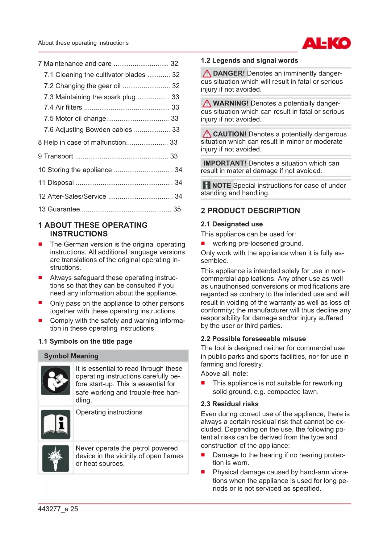
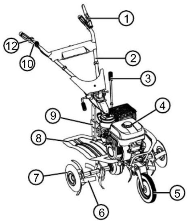
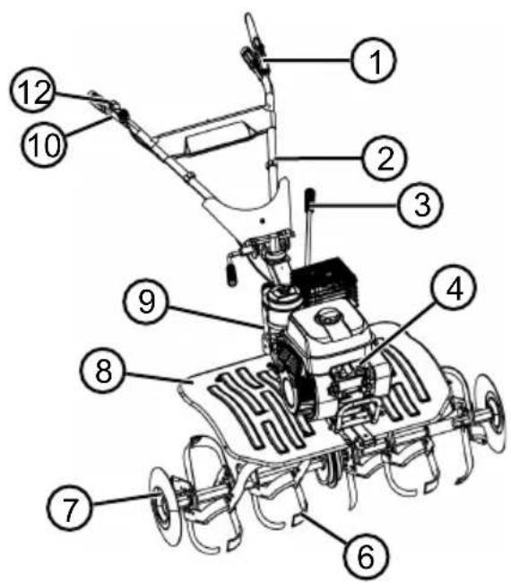
2.7 Product overview (01, 09, 18)
The product overview (01, 09, 18) provides an overview of the appliance.
No. Component
| 1 Clutch lever |
| 2 Handlebar |
| 3 Gear selector lever |
| 4 Engine |
| 5 Transport wheel |
| 6 Cultivator blades |
| 7 Protective discs |
| 8 Guard plate |
No. Component
9 Depth skid
10 Throttle lever
11 Reverse lever
12 Engine switch
3 SAFETY INSTRUCTIONS
⚠️ DANGER! Danger of fatal injury and danger of extremely severe injury! Lack of knowledge of the safety instructions and operating instructions can lead to extremely serious and even fatal injury.
- Observe all safety instructions and instructions for use in these operating instructions as well the operating instructions which are referred to before you start using the appliance.
-
Keep all supplied documents in a safe place for future reference.
■ Danger of fatal injury from gas poisoning The exhaust fumes from the cultivator contain carbon monoxide which can kill a person in a few minutes. Observe the following before and during use: -
Only operate the cultivator in the open air, never indoors.
- Do not inhale the motor exhaust gases.
- Switch off the cultivator if feeling nauseous, dizzy, or weak while using this appliance.
■ Only use the cultivator if it is in perfect technical condition.
■ Do not disable safety and protective devices.
■ Wear hearing protection.
■ Carefully read and follow these operating instructions and the operating instructions for the motor. Learn how to stop the cultivator quickly.
■ Do not use starter sprays or similar.
3.1 Operator
■ Young people under 16 years of age and people who do not know the operating instructions are not allowed to use the tool. Observe any country-specific safety regulations regarding the minimum age of the user.
■ Inexperienced operating personnel must be instructed and trained in the operation of the appliance.
- Do not operate the appliance if you are under the influence of alcohol, drugs or medication.
3.2 Appliance safety
■ Use the appliance only under the following conditions:
■ The appliance is not soiled.
■ The appliance show no signs of damage.
■ All controls function properly.
- Do not overload the device. It is intended for light work in the private sector. Overload can lead to damage to the appliance.
■ Never operate the appliance with worn or defective parts. Always replace defective parts with original spare parts from the manufacturer. If the appliance is operated with worn or defective parts, guarantee claims against the manufacturer are excluded.
■ Repair work is only allowed to be carried out by expert workshops or our service centres.
3.3 Safety of persons, animals and property
■ Use the appliance only for the purposes for which it is intended. Any non-intended use can lead to injury and property damage.
■ Switch on the appliance only when there are no persons or animals in the working area.
- Maintain a safe distance to persons or animals, or switch off the appliance if persons or animals approach.
■ Never direct the exhaust gas jet of the engine towards persons and animals or towards inflammable products and objects.
- Do not reach into the vacuum and vent grilles when the engine is running. Injuries can occur due to rotating appliance parts.
■ Always switch off the appliance when not in use, e.g. when changing the work area, during service and maintenance, and when filling with the petrol/oil mixture.
- Immediately switch off the appliance if there is an accident in order to avoid further injuries and/or property damage.
■ Never operate the appliance with worn or defective parts. Worn or defective appliance parts can cause serious injuries.
- Keep the appliance out of the reach of children.
3.4 Safety in the workplace
■ Work only in daylight or under very bright artificial light.
■ Only operate the appliance on solid and level ground and not on sharp inclines.
■ The appliance should not be used on rocky terrain.
■ Always operate parallel to the slope.
- Do not operate the appliance up or down the slope, as well as on slopes with a gradient of more than 10^ .
■ Pay attention to stability.
■ Remove foreign bodies from the working area.
- Do not place your hands and feet close to any rotating parts.
■ Never lift or carry the appliance when the motor is running.
No one should be standing in front of the appliance and/or cultivator blades when starting the motor – the drive of the cultivator blades must be turned off.
■ When attaching and removing the transport wheel and/or when adjusting the depth skid, the motor must be turned off and the cultivator blades must be upright.
■ When moving the appliance using the attached transport wheel, turn off the motor and wait for the cultivator blades to come to a standstill.
■ The appliance may only be operated by maintaining the safety distance provided by the handlebar.
- Keep the exhaust and motor clean.
■ Renew the tank or tank cap if damaged.
3.5 Handling of petrol and oil
Risk of explosion and fire:
An escaping petrol/air mixture can cause an explosive atmosphere. Deflagation, explosion and fire can lead to serious and even fatal injuries if fuel is not handled properly. Observe the following:
- Do not smoke when dealing with petrol.
- Only handle petrol out of doors and never in enclosed spaces.
It is essential to heed the code of conduct stated below.
■ Only transport and store petrol and oil in containers approved for that purpose. Ensure that children have no access to stored petrol and oil.
In order to avoid ground contamination (environmental protection) when filling, ensure
that no petrol or oil enters the soil. Use a funnel for filling.
■ Never fill the appliance in enclosed spaces. Petrol vapours may gather at ground level, and thereby result in a deflagration or even an explosion.
- Immediately wipe any spilled petrol off the appliance and the ground. Allow textiles used to wipe off petrol to dry in a well ventilated place before disposing of them. Otherwise, sudden self-ignition may occur.
If petrol has been spilled, petrol vapours occur. For this reason, do not start the appliance at the same location but at least 3 m away.
- Avoid skin contact with mineral oil products. Do not inhale petrol vapours. When filling, always wear protective gloves. Change and clean protective clothing regularly.
■ Ensure that your clothing does not come into contact with petrol. If petrol has got onto your clothing, change it immediately.
■ Never fill the fuel tank while the engine is running or hot.
3.6 Personal protective equipment
It is recommended to wear clothing and protective equipment in accordance with the regulations in order to avoid injury to the head and limbs as well as to avoid hearing impairment.
The clothing should be appropriate (tightly fitting) and must not restrict movements. If you have long hair, it is essential to wear a hair net. Never wear loose items of clothing or accessories that be pulled into the appliance, e.g. scarves, loose-fitting shirts, long necklaces.
■ The personal protective equipment comprises:
■ Hearing protection and protective eye-wear
■ Long trousers and sturdy shoes
- Protective gloves
4 ASSEMBLY
WARNING! Danger if assembly is not carried out completely! Use of an incompletely assembled device can result in serious injury.
■ Only use the device when it is fully assembled!
■ Before switching on, check that all safety and protective devices are in place and functioning correctly!
4.1 MH540
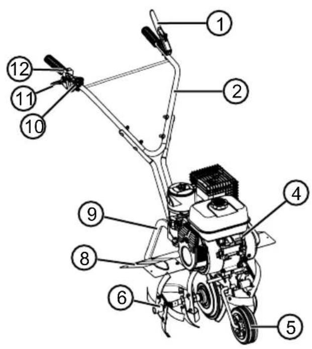
4.1.1 Installing the cultivator blades (02)
- Fit the supplied cultivator blade sets (02/1) onto the preassembled cultivator blade sets (02/2).
- Position the cultivator blade set so that the holes are aligned with one another.
- Insert the clip pin (02/3) through the hole and secure.
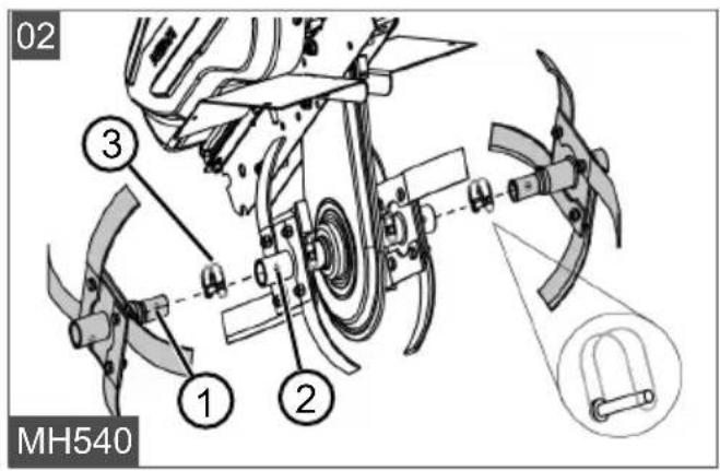
4.1.2 Installing the depth skid (03)
- Move the fastening sleeve of the depth skid (03/1) into the base carrier (03/2) (03/a).
- Insert the hexagon bolt (03/3) through the hole and screw on the nut.
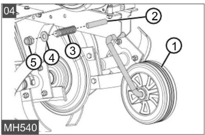
4.1.3 Installing the transport wheel (04)
- Move the wheel mount with transport wheel (04/1) through the hole into the front base carrier (04/2).
- Push on the spring (04/3).
- Fit the washer (04/4) and nut (04/5) and tighten.
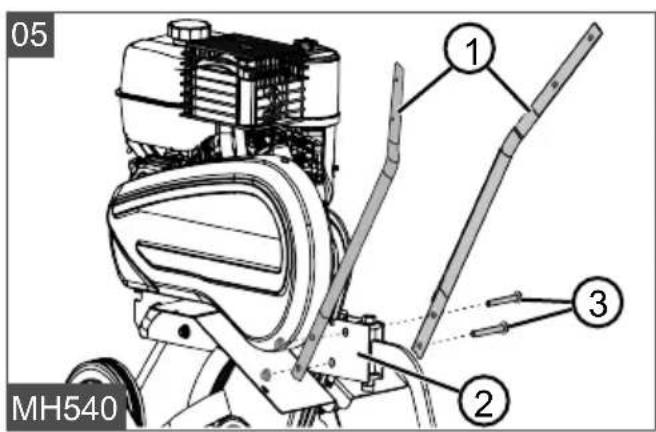
4.1.4 Installing the handlebar with handle (05 - 06)
- Position both lower braces (05/1) on the base carrier (05/2) so that the holes are aligned.
- Fully insert the bolts (05/3).
- Fit nuts and tighten.
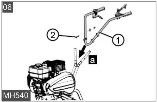
- Position the upper brace (06/1) on the lower brace (06/a) so that the holes are aligned.
- Fully insert the bolts (06/2).
- Fit washers and nuts, and tighten.
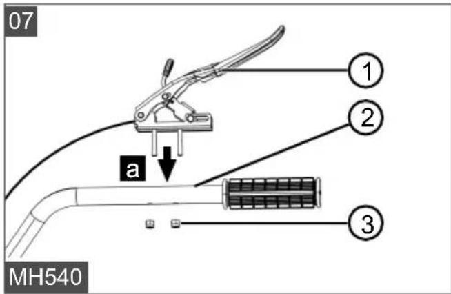
4.1.5 Installing the clutch lever (07)
- Insert the clutch lever (07/1) with threaded pins through the holes on the handlebar (07/2).
- Fit nuts (07/3) and tighten.
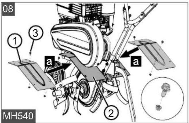
4.1.6 Installing the guard plate (08)
The guard plates are installed to the right and left of the engine in the same way.
- Position (08/a) the guard plate (08/1) on the holding plate (08/2) so that the holes are aligned with one another.
- Insert the bolts (08/3) from above into the holes.
- Fit nuts and tighten.
4.2 MH770
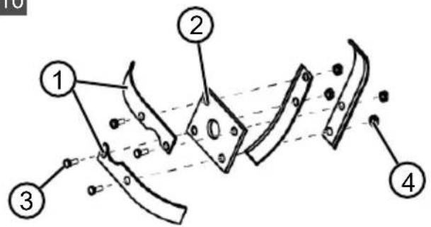
4.2.1 Preassembling the cultivator blades (10)
Four cultivator blades are mounted onto each shaft fastening plate.
- Place two cultivator blades (10/1) on each side of the fastening plate (10/2). In the process, position each cultivator blade offset by 90° to the next blade.
- Insert four bolts (10/3) through the holes in the cultivator blade and fastening plate.
- Screw on the nut (10/4).
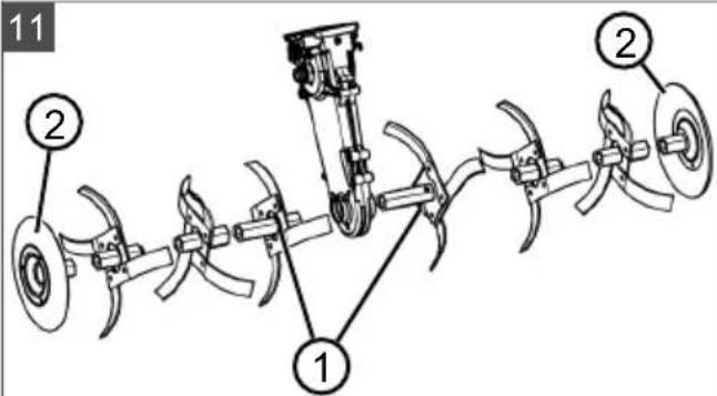
4.2.2 Installing the cultivator blades (11)
- On both sides, fit a cultivator blade set (11/1) onto the axle mount.
- Fit additional cultivator blade sets.
- Connect all cultivator blade sets together with clip pins.
- Fit a protective disc (11/2) on both sides and secure using a clip pin on each.
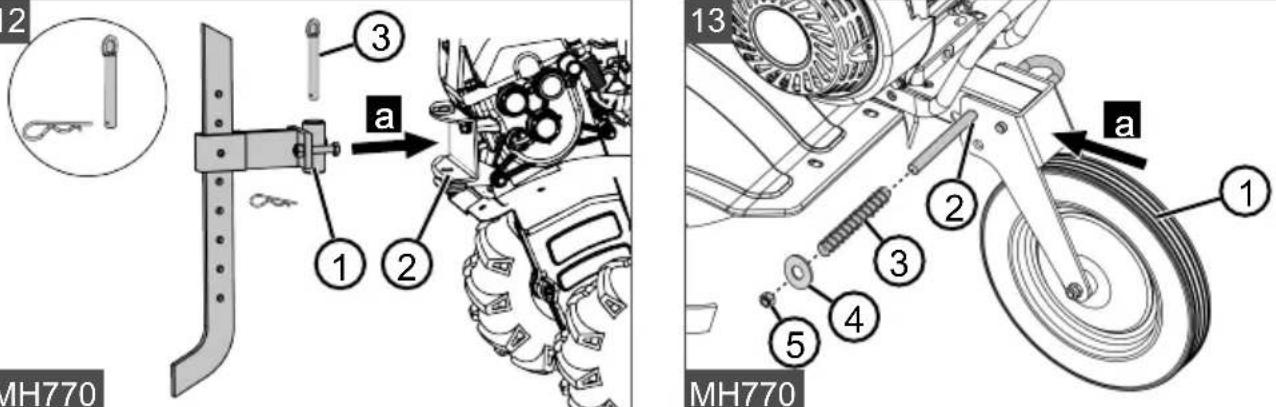
4.2.3 Installing the depth skid (12)
- Insert the fastening sleeve of the depth skid (12/1) into the base carrier (12/2) (12/a).
- Slide the locking pin (12/3) through the hole and secure with spring split pin.
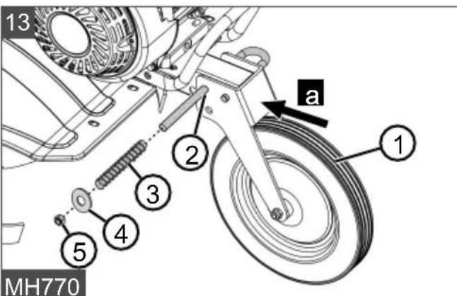
4.2.4 Installing the transport wheel (13)
- Slide the wheel mount with transport wheel (13/1) onto the front base carrier (13/a), so that the holes are aligned.
- Insert wheel mount through the hole (13/2).
- Slide the spring (13/3) onto the wheel mount.
- Fit the washer (13/4) and nut (13/5) and tighten.
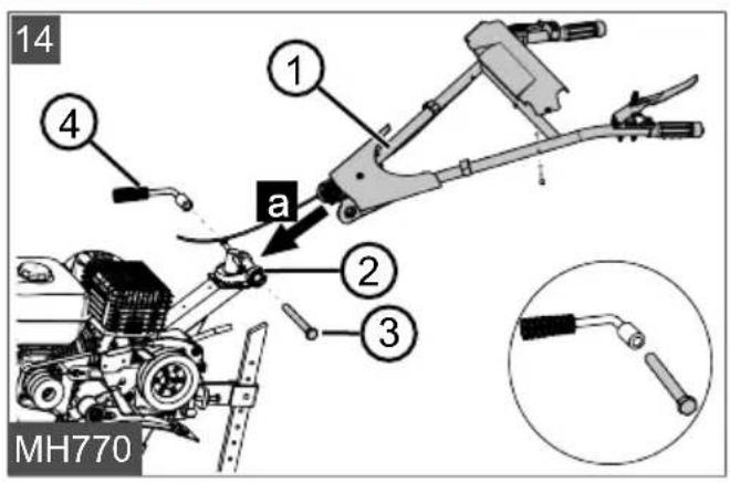
4.2.5 Installing the handlebar with handle (14)
- Position (14/a) the handlebar (14/1) on the base carrier (14/2).
-
Insert the bolt (14/3) through the grid joint.
-
Fit the clamping lever (14/4) and tighten.
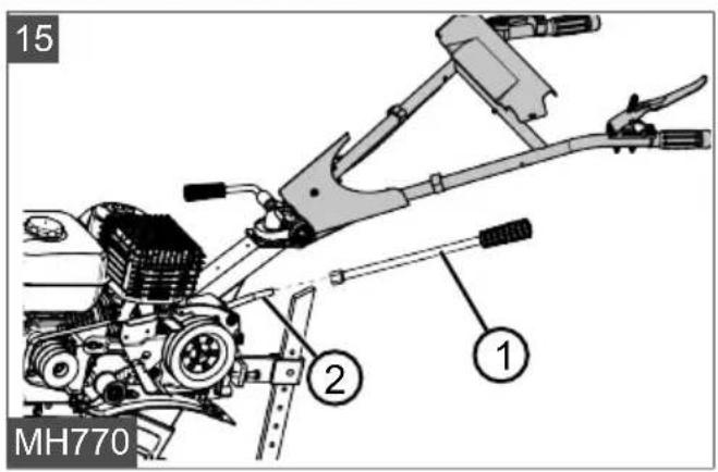
4.2.6 Installing the gear lever (15)
- Screw the handle (15/1) onto the gear lever (15/2).
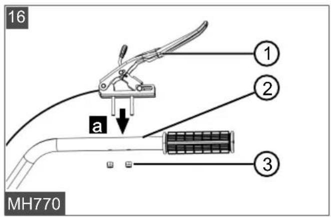
4.2.7 Installing the clutch lever (16)
-
Insert the clutch lever (16/1) with threaded pins through the holes on the handlebar (16/2).
-
Fit nuts (16/3) and tighten.
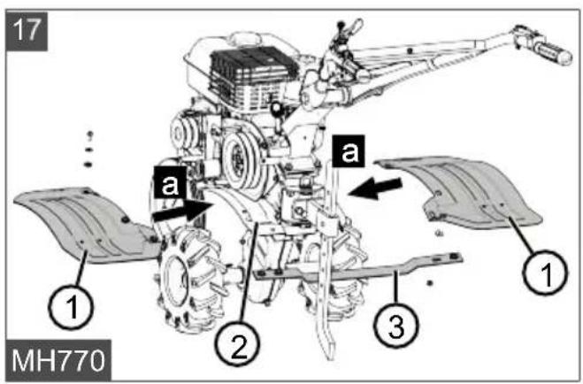
4.2.8 Installing guard plates (17)
The guard plates are installed to the right and left of the engine in the same way.
-
Position (17/a) the guard plate (17/1) on the holding plate (17/2) so that the holes are aligned with one another.
-
Position cross struts (17/3) from below onto the guard plates.
-
Insert the bolts from above through the holes.
-
Fit nuts and tighten.
4.3 MH1150
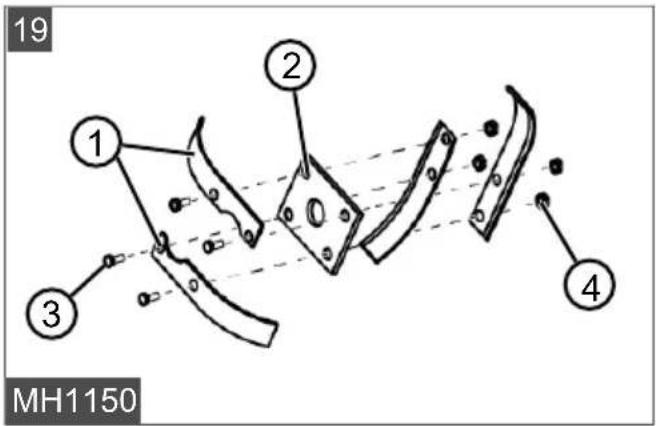
4.3.1 Preassembling the cultivator blades (19)
Four cultivator blades are mounted onto each shaft fastening plate.
-
Place two cultivator blades (19/1) on each side of the fastening plate (19/2). In the process, position each cultivator blade offset by 90^ to the next blade.
-
Insert four bolts (19/3) through the holes in the cultivator blade and fastening plate.
-
Screw on the nut (19/4).
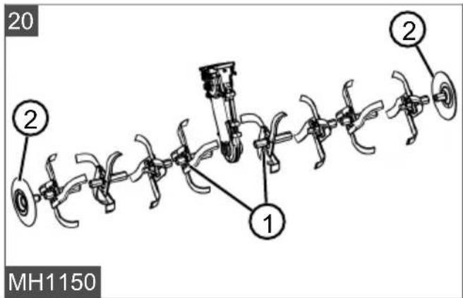
4.3.2 Installing the cultivator blades (20)
-
On both sides, fit a cultivator blade set (20/1) onto the axle mount.
-
Fit additional cultivator blade sets.
-
Connect all cultivator blade sets together with clip pins.
-
Fit a protective disc (20/2) on both sides and secure using a clip pin on each.
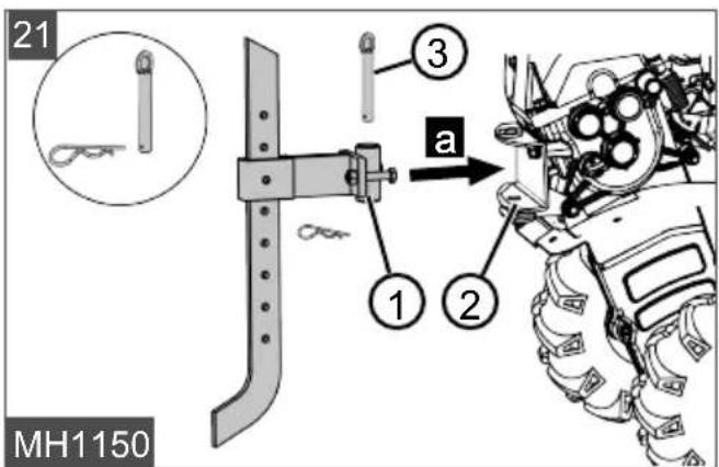
4.3.3 Installing the depth skid (21)
-
Insert the fastening sleeve of the depth skid (21/1) into the base carrier (21/2) (21/a).
-
Slide the locking pin (21/3) through the hole and secure with spring split pin.
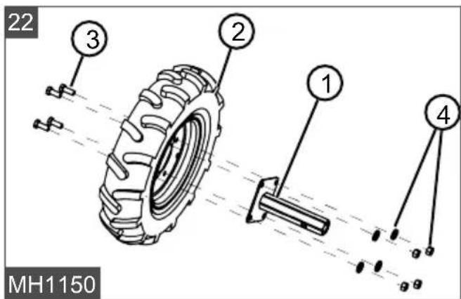
4.3.4 Fitting the impellers (22, 23)
Preassembling the impellers (22)
The valve must be located on the outside of the impeller.
- Align wheel hub (22/1) on the inside of the impeller (22/2) so that the holes are aligned.
- Insert four hexagon bolts (22/3) through the holes from the outside.
- Fit the washers and nuts (22/4) and tighten.
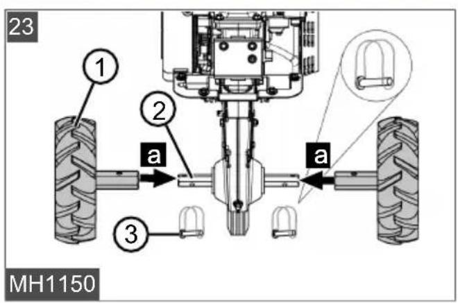
Fitting the impellers (23)
- Place the impeller (23/1) onto the axis (23/2) (23/a).
- Align the impeller until the holes on the wheel hub and axis are aligned.
- Insert the clip pin (23/3) through the hole and secure.
- Install the second impeller in the same way.
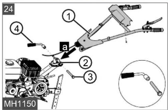
4.3.5 Installing the handlebar with handle (24)
- Position (24/a) the handlebar (24/1) on the base carrier (24/2).
- Insert the bolt (24/3) through the grid joint.
- Fit the clamping lever (24/4) and tighten.
4.3.6 Installing the gear lever (25)
- Screw the handle (25/1) onto the gear lever (25/2).
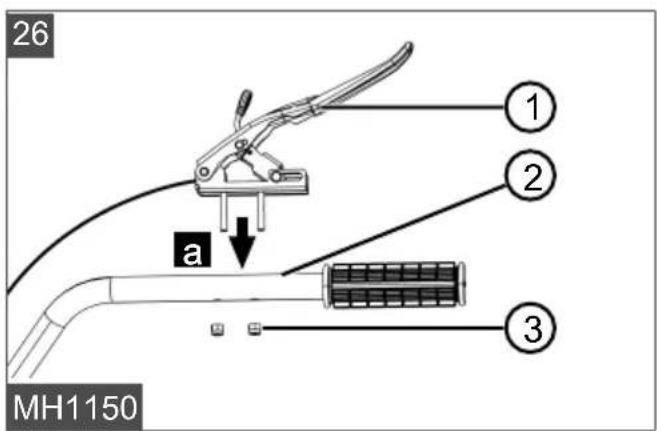
4.3.7 Installing the clutch lever (26)
- Insert the clutch lever (26/1) with threaded pins through the holes on the handlebar (26/2).
- Fit nuts (26/3) and tighten.
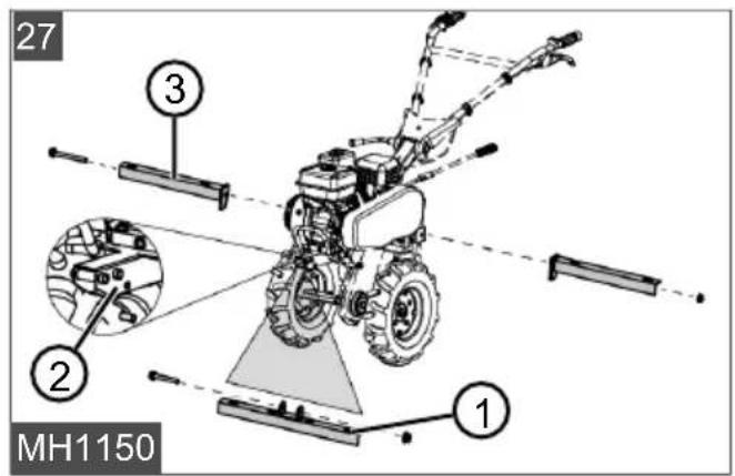
4.3.8 Installing the guard plate (27, 28)
- Place the front cross beam (27/1) centrally on the base carrier (27/2) so that the holes are aligned.
- Fully insert the hexagon bolt and tighten nut.
- Place rear cross beams (27/3) on the right and left of the base carrier.
- Fully insert the hexagon bolt and tighten nut.
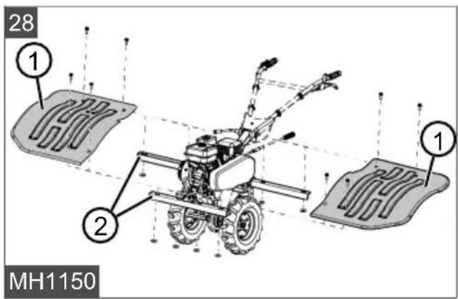
- Place the guard plates (28/1) on the cross beams (28/2).
- Insert bolts with washers from above through the guard plate and cross beams.
- Fit nuts from below and tighten.
5 START-UP
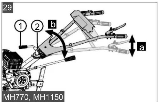
5.1 Adjusting the handlebar MH770, MH1150 (29)
Adjust the height of the handlebar
The normal height adjustment corresponds to hip height.
- Loosen the clamping lever (29/1) on the lower end of the handlebar.
- Incline the handlebars until the appropriate height has been reached (29/a).
- Tighten the clamping lever.
Adjusting the sideways position of the handlebar
Sideways adjustment of the handlebar makes it possible to avoid walking on the surface already processed. The handlebar can be adjusted by 35^ to either side.
- Turn the rotary handle (29/2) slightly until the handlebar can be moved laterally.
- Turn the handlebar to the left or right into the required position (29/b).
- Tighten the rotary handle.
6 OPERATION
WARNING! Risk of injury due to detaching appliance parts. Appliance parts detaching during operation can lead to serious injury.
■ Before turning the appliance on, check that all the parts of the appliance are firmly tightened.
■ Attach cutting tools so that they cannot detach during operation.
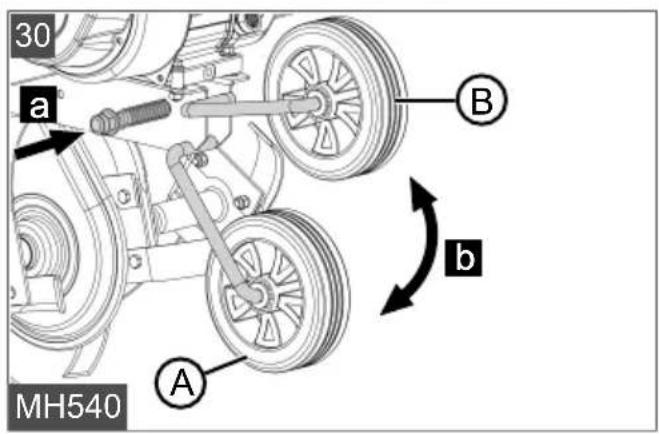
6.1 Rolling the cultivator to the work location (30, 31)
MH540 (30)
To roll the cultivator, move the transport wheel to the transport position (30/A).
- Pull the wheel mount to the right (30/a).
- Swivel the wheel downwards (30/b) and engage securely.
Before soil cultivation, move the transport wheel into the working position (30/B).
- Pull the wheel mount to the right (30/a).
- Swivel the wheel downwards (30/b) and engage securely.
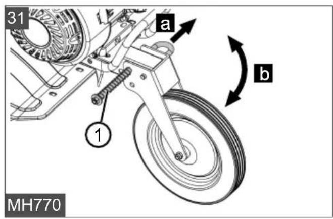
MH770 (31)
Move the transport wheel into working position before cultivation:
- Pull the wheel mount (31/1) to the right (31/a).
- Swivel the transport wheel upwards (31/b).
- Push the wheel mount (31/1) back through the hole.
Swivelling into the transport position is carried out in the same way.
MH1150
Install the impellers for transport:
- see chapter 4.3.4 "Fitting the impellers (22, 23)", page 30.
For soil cultivation, disassemble the impellers and install the cultivator blade sets:
- see chapter 4.3.2 "Installing the cultivator blades (20)", page 30.
6.2 Filling with fuel
NOTE For more detailed information, please refer to the separate operating instructions for the engine.
6.3 Stopping the motor and switching off
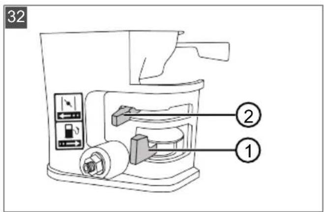
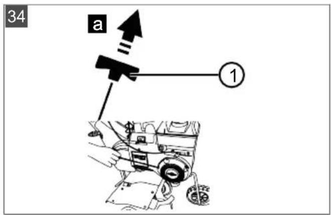
6.3.1 Starting the engine (32 - 34)
- Push the petrol cock (32/1) in the direction of the arrow to open the petrol supply.
- Only if the engine is cold: Move choke lever (32/2) in the direction of the arrow.
- Press engine switch "ON" (33/1).
- Turn the throttle lever (33/3) to the left so that the arrow points to H (high).
- Pull the starter cable (34/1) out briskly (34/a), and then allow it to wind back in slowly.
The engine begins running.
- If the engine is running smoothly: Push the choke lever in the opposite direction of the arrow back to the end stop.
- If the engine is not running: Check work steps and pull the starter cable again.
- If the engine stutters: Move choke lever slightly in the direction of the arrow.
6.3.2 Switch off the engine (32, 33)
- Turn the throttle lever (33/3) to the right so that the arrow points to L (low).
- Press engine switch "OFF" (33/2).
- Push the petrol cock (32/1) away from the direction of the arrow to close the petrol supply.
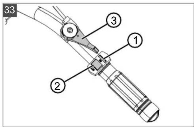
6.4 Cultivator blades
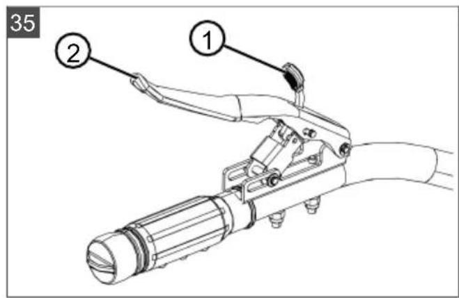
6.4.1 Switching on the cultivator blades (35)
- Press and hold the safety button (35/1).
- Press the clutch lever (35/2) on the handlebar firmly downwards.
After the lever has travelled halfway, the cultivator blades begin to rotate and the cultivator starts moving. Once the clutch lever has been pressed fully downwards, the cultivator blades are completely engaged.
6.4.2 Switching off the cultivator blades (35)
WARNING! Danger from rotating appliance parts! Reaching into rotating appliance parts will result in serious injuries.
■ Never reach into rotating parts.
■ The cultivator blades must not rotate when the clutch lever is released.
- Release the clutch lever (35/2).
The cultivator stops.
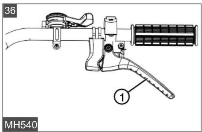
6.5 Engaging/releasing reverse gear, MH540 (36)
-
see chapter 6.4.1 "Switching on the cultivator blades (35)", page 32.
-
Pull the reverse gear lever (36/1) up to the stop.
Disengaging reverse gear:
- Release the reverse gear lever (36/1).
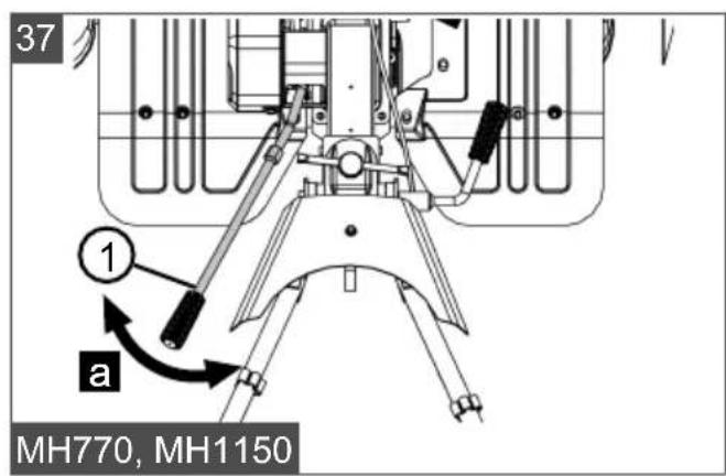
6.6 Operating the gear shift, MH770, MH1150 (37)
The cultivator has 2 forward gears and 1 reverse gear.
The first forward gear is intended for hard ground; the cultivator blades turn slowly. The second forward gear is intended for less hard ground; the cultivator blades turn faster.
- Release the clutch lever (see chapter 6.4.2 "Switching off the cultivator blades (35)", page 32).
- Turn the gear lever (37/1) in such a way that it coincides with the required gear on the plate (37/a) for the gear display (1 = 1st gear, 2 = 2nd gear, R = reverse gear).
- Press the safety button and firmly press the clutch lever on the handlebar downwards (see chapter 6.4.1 "Switching on the cultivator blades (35)", page 32).
6.7 Using the depth skid
- Push down the cultivator handlebar and thus also the depth skid to slow down the speed of the cultivator and to influence the cultivation depth.
- Raise cultivator handlebar and thus also the depth skid to increase the speed of the cultivator.
7 MAINTENANCE AND CARE
⚠️ DANGER! Danger of fatal injury and danger of extremely severe injury. Danger of fatal injury and danger of extremely severe injury when the engine is switched on.
- Carry out all work with the engine switched off.
⚠️ DANGER! Risk of injury or death due to improper maintenance. Maintenance work carried out by unqualified persons and the use of non-approved spare parts can result in serious injuries and even death during operation of the appliance.
- Do not remove or deactivate any safety installations.
■ Use only approved OEM spare parts.
■ Ensure through regular and proper maintenance that the appliance is in a clean and functional condition at all times.
CAUTION! Risk of injury. Sharp-edged and moving appliance parts can lead to injury.
■ Always wear protective gloves during maintenance, care and cleaning work!
7.1 Cleaning the cultivator blades
Before and after using the cultivator, remove fibrous plant matter and large clods of earth from the cultivator blades.
7.2 Changing the gear oil
In general, the gear oil should also be changed every 100 working hours (oil viscosity SAE 80).
Oil change
Required oil amount: approx. 0.5 l.
- Unfasten the yellow oil plug screw on the front of the transmission.
- Vacuum out the used oil.
- Fill with new oil.
-
Close the filler opening with the screw plug.
-
Dispose of used oil in accordance with the statutory regulations.
i NOTE The oil must be visible at the filler opening.
7.3 Maintaining the spark plug
i NOTE For more detailed information, please refer to the separate operating instructions for the engine.
7.4 Air filters
NOTE For more detailed information, please refer to the separate operating instructions for the engine.
7.5 Motor oil change
NOTE For more detailed information, please refer to the separate operating instructions for the engine.
7.6 Adjusting Bowden cables
The fine adjustment is made using the adjusting bolt on the handlebar and on the engine mount.
- Unfasten the lock nut on the adjusting bolt.
-
Turn the adjusting bolt to lengthen or shorten the Bowden cable.
-
Re-tighten the lock nut.
NOTE The cultivator blades may begin to turn when the lever is only pressed halfway up.
Throttle cable
NOTE For more detailed information, please refer to the separate operating instructions for the engine.
8 HELP IN CASE OF MALFUNCTION
NOTE For malfunctions that are not listed in this table or that you cannot resolve yourself, please contact our customer service.
| Malfunction Cause Remedy | ||
| Engine loses power. Air filter clogged Check and clean air filter | ||
| Combustion problems Contact a service centre | ||
| Cultivator blades dirty Clean the cultivator blades | ||
| Engine does not start. Lack of fuel Top up with fuel | ||
| Poor quality, contaminated fuel, old fuel in tank | Empty tank and fill with fresh fuel | |
| Incorrect starting procedure Perform the starting process correctly | ||
| Throttle lever in the wrong position | Move the throttle lever to the "START" position | |
| Defective spark plug See instructions for the engine. | ||
| Air filters See instructions for the engine. | ||
| Cultivator blades do not turn | V-belt defective | Contact a service centre |
| Gearbox damage | Contact a service centre | |
| Cultivator blade loose Tighten the cultivator blade | ||
| Bowden cable stretched or loose | Adjust Bowden cable | |
9 TRANSPORT
■ Only transport the cultivator with an empty fuel tank.
■ Always transport the cultivator horizontally, otherwise this can cause:
Leaking fuel and oil
Generation of smoke
Starting difficulties
■ Soot on spark plug
10 STORING THE APPLIANCE
Thoroughly clean the appliance after each use and – if present – attach all covers. Store the appliance in a dry, lockable place out of the reach of children.
If the appliance is not going to be used for more than 2 – 3 months, the following work is necessary to avoid any damage:
- Empty the fuel tank:
- Allow the engine to run until it stops itself. Then there is no longer any petrol/oil mixture in the fuel tank or carburettor and deposits cannot form.
- Cleaning the appliance:
■ Wipe the entire appliance and accessory parts with a cleaning rag. Do not use petrol or other solvents!
■ Remove any dirt from all appliance openings (including cooling openings for the engine).
-
Oiling the cylinder:
-
Allow the appliance to cool down completely.
■ Remove the spark plug connector and unscrew the spark plug. -
Drop a little oil into the spark plug opening.
■ Slowly pull on the starter handle so the piston moves and the oil is distributed in the cylinder. -
Set down the appliance on the transport wheel and do not stored in a tilted position.
-
Store the appliance in a cool, dry place.
11 DISPOSAL

Petrol and motor oil do not belong in household waste or the public sewer system, but should be collected and disposed of separately.
■ Before disposing of the device you must empty the fuel tank and the engine oil tank!
■ Packaging, equipment and accessories are made from recyclable materials, and must be disposed of accordingly.
12 AFTER-SALES/SERVICE
In the event of questions of warranty, repair or spare parts, please contact your nearest AL-
KO Service Centre. These can be found on the Internet at:
www.al-ko.com/service-contacts
13 GUARANTEE
We will resolve any material or manufacturing faults on the appliance during the legal warranty period for claims relating to faults, in accordance with our choice either to repair or replace. The legal warranty period is determined by the legislation of the country in which the appliance was purchased.
Our warranty promise applies only if:
■ These operating instructions are heeded
■ The appliance is handled correctly
■ Original spare parts have been used
The warranty becomes void in the case of:
■ Unauthorised repair attempts
■ Unauthorised technical modifications
Non-intended use
The guarantee excludes:
■ Paint damage that can be attributed to normal wear and tear
■ Wear parts that are marked with a frame xxxxxx (x) on the spare parts card
■ Internal combustion engines (these are covered by the guarantee provisions of the corresponding engine manufacturers)
The guarantee period commences with purchase by the first end user. The date on the proof of purchase is decisive. In the event of a guarantee claim, please take this guarantee declaration and the original proof of purchase, and contact your dealer or the nearest authorised customer service centre. This statement does not affect the purchaser's statutory claims for defects against the vendor.
OVERSÆTTELSE AF DEN ORIGINALE BRUGSANVISNING
Indholdsfortegnelse
2 = 2. gear (hurtig hastighed)
1 = 1. gear (mellem hastighed)
2.6 Leveringsomfang
Leveringsomfanget omfatter de her oplistede komponenter. Kontroller, at alle komponenter er vedlagt:
Nr. Komponent
de gear (1 = 1. gear, 2 = 2. gear, R = bak-gear).
10 OPBEVARING AF APPARATET
www.al-ko.com/service-contacts
13 GARANTI
www.al-ko.com/service-contacts
13 TAKUU JA TUOTEVASTUU
www.al-ko.com/service-contacts
13 GARANTIE
www.al-ko.com/service-contacts
13 JAMSTVO
Možebitne greške u materijalu ili proizvodnji na uređaju uklonit ćemo tijekom zakonskoga roka zastare za jamstvo na nedostatke prema vlastitom izboru popravljanjem ili zamjenskom dostavom. Rok zastare određuje se prema pravu države u kojoj je uređaj kupljen.
www.al-ko.com/service-contacts
13 GARANTIJA
www.al-ko.com/service-contacts
13 GARANTIJA
2 PRODUCTOMSCHRIJVING
2.1 Beoogd gebruik
Alleen MH770, MH1150:
0 = stationaire loop
6.7 Remspoor benutten
www.al-ko.com/service-contacts
13 GARANTIE
5 Igangsetting....134
5.1 Justere styrestangen MH770, MH1150 (29)....134
6 Betjening ....134
7 VEDLIKEHOLD OG PLEIE
www.al-ko.com/service-contacts
13 GARANTI
www.al-ko.com/service-contacts
13 ГАРАНТИЯ
Endast MH770, MH1150:
- 1 = Backväxel
0 = Tomgång
www.al-ko.com/service-contacts
13 GARANTI
www.al-ko.com/service-contacts
13 ZÁRUKA
12 SERVISNA SLUŽBA/SERVIS
www.al-ko.com/service-contacts
13 GARANCIJA
Pouze MH770, MH1150:
-1 = zpětný chod
0 = volnoběh
www.al-ko.com/service-contacts
13 ZÁRUKA
www.al-ko.com/service-contacts