MH 4005 - Milling machine AL-KO - Free user manual and instructions
Find the device manual for free MH 4005 AL-KO in PDF.

User questions about MH 4005 AL-KO
0 question about this device. Answer the ones you know or ask your own.
Ask a new question about this device
Download the instructions for your Milling machine in PDF format for free! Find your manual MH 4005 - AL-KO and take your electronic device back in hand. On this page are published all the documents necessary for the use of your device. MH 4005 by AL-KO.
USER MANUAL MH 4005 AL-KO
natural_image
Technical line drawing of two tilliwhe machines with hydraulic blades and levers (no text or symbols)DE
EN
NL
FR
IT
SL
CS
PL
SK
HU
DA
SV
NO
FI
RU
UA


Inhaltsverzeichnis
EN Instructions for use....14
AL-KO KOBER GROUP Kötz, Germany
This documentation or excerpts therefrom may not be reproduced or disclosed to third parties without the express permission of the AL-KO KOBER GROUP.
01
05
natural_image
Technical line drawing of a mechanical device with no visible text or symbols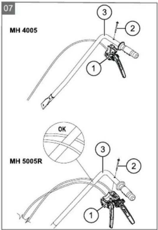
natural_image
Technical line drawing of a robotic arm with mechanical components and a highlighted lever (no text or symbols)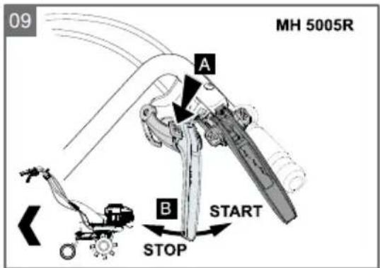
| MH 4005Art.Nr.: 113 255 | MH 5005 RArt.Nr.: 113 256 | ||
| ca. 1300 x 400 x 1110 mm ca. 1300 x 500 x 1110 mm | |||
 | 29 kg 41 kg | ||
 | B&S E-Series 4503100 min ^-1 ; 1,66 kW | B&S E-Series 6252900 min ^-1 ; 2,40 kW | |
 | 40 cm 50-75 cm | ||
 | max. 120 min ^-1 | max. 130 min ^-1 | |
 |  |  |  |
 | |||
 | a_vhw = 8,6 m/s^2 (K= +/- 4,3 m/ s^2) EN 709e ISO 5349 | a_vhw = 7,2 m/s^2 (K= +/- 3,6 m/ s^2) EN 709e ISO 5349 | |
 | LpA: 78,9 dB(A) LpA: 83 dB(A) | ||
 | LwA: 93 dB(A) LwA: 93 dB(A) | ||
Safety instructions....14
Assembly....15
Startup....16
Maintenance and care.... 16
Storage....17
Accessory parts....17
Disposal....17
Troubleshooting....18
EU declaration of conformity....19
Guarantee....19
ABOUT THIS HANDBOOK
Read this documentation before starting up the machine. This is a precondition for safe working and flawless operation.
- Observe the safety warnings in this documentation and on the product.
This documentation is a permanent integral part of the product described and must be passed on to the new owner if the product is sold.
Explanation of symbols

CAUTION!
Following these safety warnings carefully can prevent personal injury and/or material damage.

Special instructions for greater ease of understanding and improved handling.
PRODUCT DESCRIPTION
Designated use
This device is only intended for use on pre-cultivated soil.
This device is not suitable for use on solid soil, e.g. compacted turf.
The continued use of this device with original spare parts is only allowed in accordance with their purpose. Any other use is not permitted.
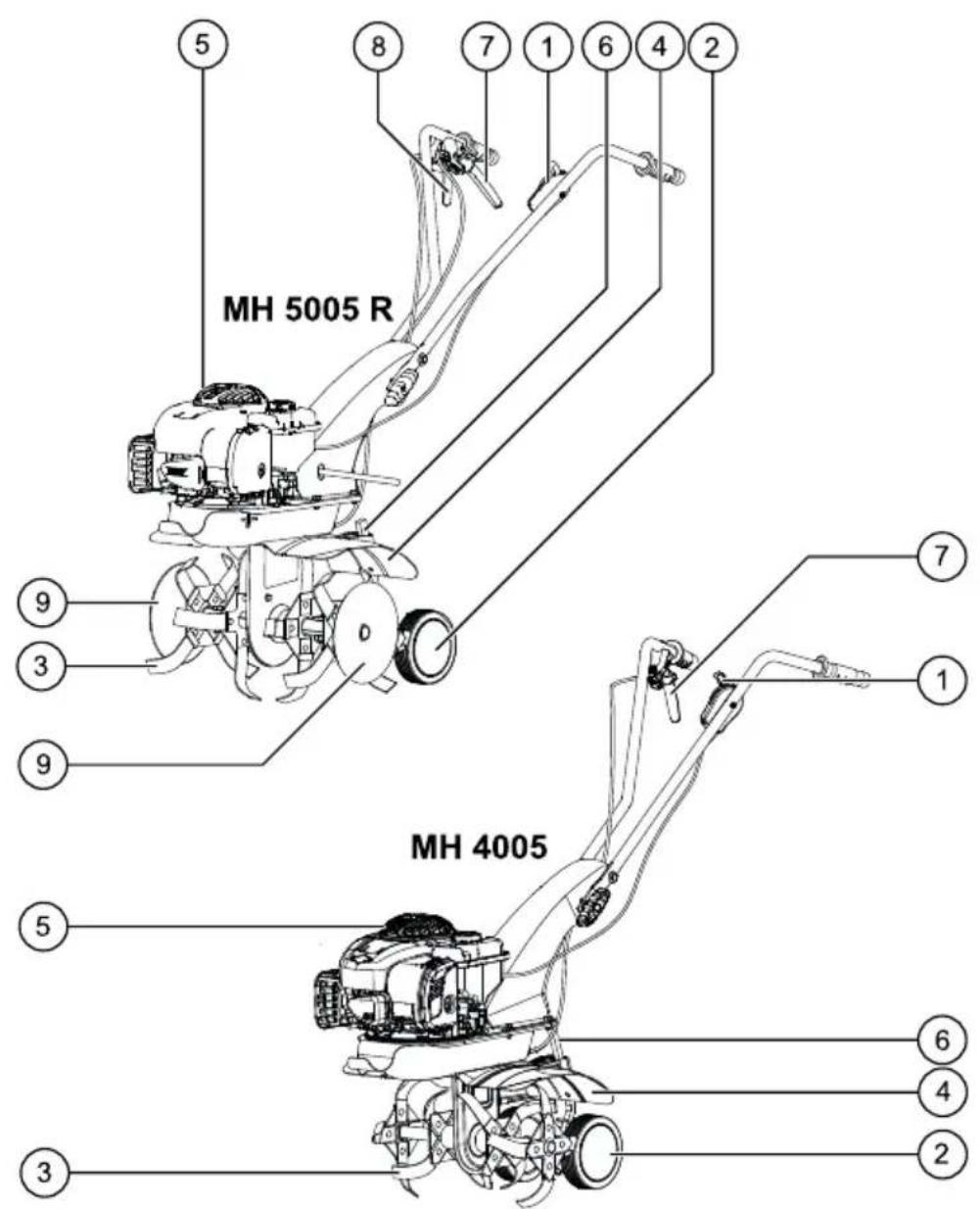
Product overview
| 1 Throttle lever 6 Depth skid | |
| 2 Transport wheel 7 Clutch lever | |
| 3 Tiller blades 8 Reverse lever | |
| 4 Guard plate extension | 9 Protective discs |
| 5 Starter cable | |
Symbols on the machine

Before starting operation, read the operating instructions!

Rotating tool! Keep your hands and feet away!
SAFETY INSTRUCTIONS

WARNING!
Fire danger! Petrol is highly flammable!

WARNING!
Risk of poisoning!

CAUTION!
Danger of burns!
The exhaust as well as the area surrounding it can heat up to 80^ .

CAUTION!
Always perform a visual check prior to start-up.
■ Young people under 16 years of age, and people who do not know the instructions for use, are not allowed to use the machine.
The device should not be used on rocky terrain.
- Observe local regulations regarding minimum age requirements for operating the machine.
Do not wear loose or baggy clothes
■ Wear sturdy, non-slip footwear
■ Remove foreign objects from the working area.
The machine is not allowed to be used in commercial applications
The machine must not be operated if the operator is under the influence of alcohol, drugs or medication.
- Observe local ordinances regarding operating times.
■ Work only when there is adequate daylight or artificial lighting.

CAUTION!
Always perform a visual check prior to start-up.
The equipment should be used only if in good order and condition
Note that the user is responsible for accidents and damage caused to other persons and/or their property
Do not deactivate safety and protection devices
Do not place your hands and feet close to any rotating parts.
■ Never lift or carry the mower while the motor is running
■ Always ensure stability when working.
The user is responsible for accidents involving other people and their property.
Do not leave the appliance unsupervised.
- Keep the exhaust and motor clean
■ Store petrol in designated containers only.
■ Only refuel in open air.
- Replace a damaged petrol tank and/or tank cap.
Only replace damaged or worn parts by genuine spare parts.
■ Subject to changes in design and configuration.
No one should be standing in front of the device and/or tiller blades when starting the motor - the tiller blade drive must be turned off.
When attaching and removing the transport wheel and/or when adjusting the depth skid, the motor must be turned off and the tiller blades must be upright.
When moving the device using the attached transport wheel, turn off the motor and wait for the tiller blades to come to a standstill.
The device may only be operated by maintaining the safety distance provided by the handlebar.
■ Always operate parallel to the slope.
Do not operate the device up or down the slope, as well as on slopes with a gradient of more than 10^ .
Do not open the tank cap or refuel with petrol while the motor is still running and while the machine is still hot.
Use a funnel or a filler pipe when refuelling so that no fuel is spilled on the engine, the deck or the ground.
Do not start the engine if petrol has overflowed. The appliance may be cleaned, and any attempt at ignition may be made, only when the petrol vapours have dissipated.
For safety reasons, never use the engine with worn or damaged parts. Such parts must always be replaced, not repaired. Use OEM spare parts. Spare parts of inferior quality can damage the engine and endanger your safety
■ Renew exhaust silencers if damaged.
Do not change the engine governor settings.
ASSEMBLY
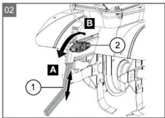
Assembly of depth skid (2)
Insert the long side of the depth skid (2-1) into the end piece of the frame arm and lock it by turning the handle (2-2).
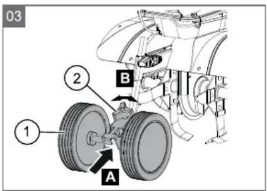
Assembly of transport wheel (3)
The transport wheel (3-1) is used to transport the cultivator.
■ Push the transport wheel (3-1) onto the depth skid and secure it using the star screw (3-2).
Remove the transport wheel during operation:
■ Loosen the wing screw (3-2) and remove the transport wheel.
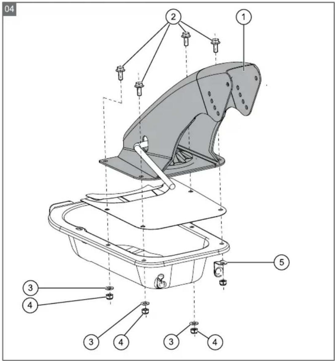
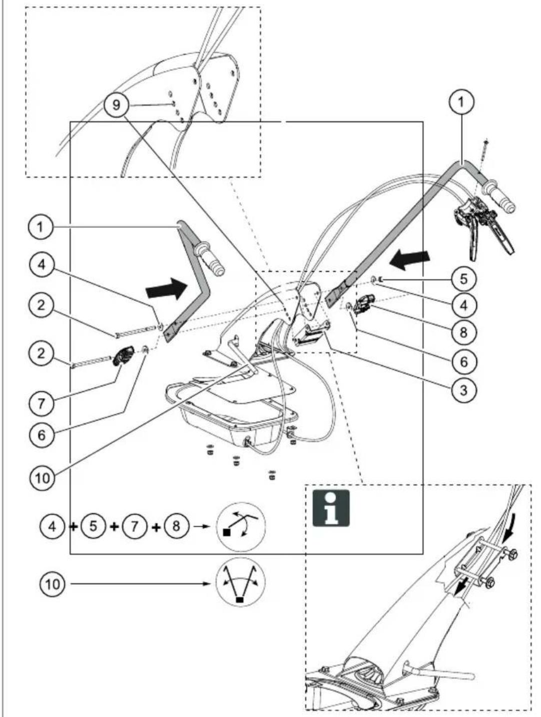
Assembly of handlebar support (4)
- Attach the support (4-1) to the cultivator using the 4 screws (4-2) already positioned on the plate along with the washers (4-3) and nuts (4-4).
- Attach the cable feed-through (4-5) as shown in the figure (4).
Fitting the handlebar (5)
■ Fasten the 2 handlebars (5-1) to support by inserting the through screw (5-2), spacer (5-3), washers (5-4) and nut (5-5) in the upper hole of the handlebar.
Proceed in the same way for the lower hole (5-9), by fitting the other screw (5-2), spacer (5-3) and the washers h.4 (5-6) in the knob (5-7) and knob (5-8) complete with nut, in the sequence shown in the illustration (5).

To prevent fraying the Bowden cables, guide the Bowden cables between the through bolts (5-2) and spacers (5-3)!
For more information, see Setting the handlebar.
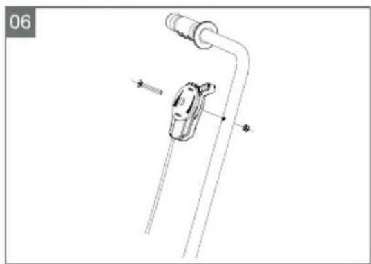
Assembly of throttle lever (6)
- Secure the throttle cable to the handlebars using a screw and hexagon nut.
Assembly of control cable (7)
- Secure the control cable (7-1) to the right handlebar (7-3) using a screw (7-2).

CAUTION!
Guide the handlebar (7-3) between both control cables.
STARTUP
Only start up the machine, after assembly is fully completed.

CAUTION!
Fill with oil and petrol before initial start-up. For this purpose, consult the supplied operating instructions from the petrol motor manufacturer.
Setting the handlebar (5)
The handlebars are height-adjustable.
1 Unscrew knobs (5-7) and (5-8), and insert the through bolt (5-2) into the hole that best suits your working requirements.
For side-adjustable version only:
2 The handlebars can be turned right or left by lifting the lever shown in (5-10).
Transport wheel
The cultivator can be easily rolled to the place of operation using the transport wheel.
1 The transport wheel should be removed when operating the cultivator. "Assembly of transport wheel (3)"
Depth skid setting (2)
To ensure that the cultivator properly tills and moves properly forward, the height of the depth skid (2-1) should be set via the fixing screw (2-2) so that the machine maintains a level operating position.
■ Once set to the correct position, tighten the fixing screw (2-2).
Starting the motor (6)
When starting the motor, the tiller blade clutch lever may not be activated.
- Move the throttle lever to the "START" position.
- Pull out the cable starter briskly, and then allow it to wind back in slowly.
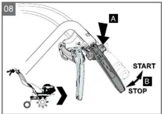
Switching on the tiller blades (8)
- Push clutch lever up fully and hold it there. The tiller blades may begin to turn when the lever is only pressed halfway up.
Switching off the tiller blades (8)
- Release the clutch lever.
Switch on the reverse gear (9)
- Pull up the reverse gear lever up to the stop.
Switching off the reverse gear (9)
- Release the reverse gear.
Switching off the motor (6)
- Move throttle lever to the "STOP".
MAINTENANCE AND CARE

CAUTION!
Risk of injury!
■ Always switch the motor off and pull the spark plug connector prior to any maintenance and care work.
Motor may continue running. Make sure that the motor has stopped after switching it off.
■ Always wear work gloves when carrying out maintenance and care jobs on the cutting blade.
■ Clean the appliance after every use
Do not spray the machine with water! Penetrating water (ignition system, carburettor...) can lead to malfunctions.

When the device is tilted to the side, the carburettor must be pointing upwards.
Expert inspection is required:
■ After running into an obstacle
If the motor stops suddenly
If there is gear damage
If the V-belt is defective
If a blade is bent
If the motor shaft is bent
Changing the gear oil
In general, the gear oil should be changed every 100 operating hours. (oil viscosity SAE 80).
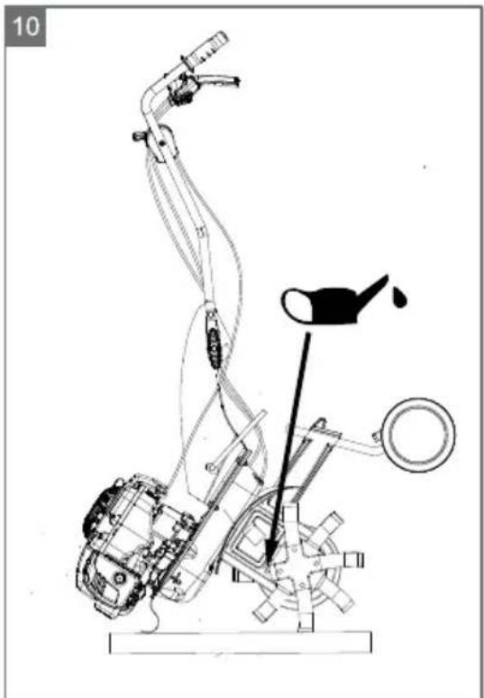
Oil change (10)
- Remove the oil drain plug.
- Set the machine at an angle and suction off the oil via a pump.
- Fill with new oil. Required oil quantity approx. 0.2 (MH4005) and 0.5 l (MH 5005 R).

Set the machine upright; open the cap and check to ensure that the oil is at the bottom level of the hole. The filling and emptying cap corresponds to the oil level.

CAUTION!
The used oil must not be drained into the sewer system or into the ground. Contaminating the ground water is a punishable offence.
Most petrol stations will dispose of your waste oil or please contact your local authority for more information.
- Close the fill opening using the screw plug.
Motor
Oil change / Air filter / Spark plug
See the instructions for use from the motor manufacturer.
Adjusting Bowden cables
The fine adjustment is made using the adjusting screw on the upper handle and on the motor mount (on the ends of the Bowden cables).
- Loosen the locknuts.
- Adjust via the adjusting screw.

Correct set-up: The tiller blades may begin to turn when the lever is only pressed halfway up.
- Re-tighten the locknuts.
Throttle cable:
See the instructions for use from the motor manufacturer.
STORAGE

CAUTION!
Fire hazard!
Do not store fuelled machine in buildings where the petrol fumes might come into contact with naked flames or sparks!

Only authorized specialized workshops or our customer service are allowed to repair the unit.
- Switch off motor, wait for the tiller blades to come to a standstill and disconnect the spark plug connector.
■ Always wear protective gloves when working on the tiller blades.
■ Only drain the petrol tank outdoors.
■ Switch off the engine and allow to cool down before removing the tank cap
Do not spray the machine with water! Water ingress can cause irreparable damage to the motor and the safety pushbutton switch.
ACCESSORY PARTS
Several different accessory parts can be attached to the location of the depth skid. Ask your specialist dealer about this.
DISPOSAL

Do not dispose of worn-out machines or spent batteries (including rechargeable batteries) in domestic waste!
The packaging, machine and accessories are made from recyclable materials, and must be disposed of accordingly.
TROUBLESHOOTING

CAUTION!
Disconnect the spark plug connector before any maintenance and cleaning work!
| Malfunction Remedy | |
| The motor does not start | Refuel with petrol |
| Move throttle lever to the "START" position | |
| Connect the spark plug connector to the spark plug | |
| Check spark plug, and replace if necessary | |
| Clean the air filter | |
| Clean the air filterThe motor loses power | |
| Clean the tiller blades of decaying plant residue | |
| Tiller blades do not turn | Bowden cable for tiller blades not adjusted correctly |
| Tiller blades loose on the gear shaft | |
| V-belt defective Customer Service Centre | |
| Gear damage Customer Service Centre |

In the event of a malfunction that you cannot rectify, please contact our Customer Service department.
EU DECLARATION OF CONFORMITY
We hereby declare that this product, in the version placed on the market by us, complies with the requirements of the harmonised EU Directives, EU safety standards and the product-specific standards.
| Product | Manufacturer Duly authorised person | |
| Cultivator | ||
| Serial number | AL-KO Geräte GmbH | Andreas Hedrich |
| G2212215 | Ichenhauser Str. 14 | Ichenhauser Str. 14 |
| D-89359 Kötz | D-89359 Kötz | |
Type EU Directives Harmonised standards
| MH 4005 | 2006/42 EC | EN 709 |
| MH 5005 R | 2004/108/EC | EN 709/A4 |
| 2000/14/EC | EN ISO 14982 | |
| 2004/26/EC |
Sound power level Conformity evaluation
| EN ISO 3744 | 2000/14/EC |
| measured / guaranteed | Annex VIII |
MH 4005: 92 dB(A) / 93 dB(A)
MH 5005 R: 92 dB(A) / 93 dB(A)
Kötz, 12/02/2015

Wolfgang Hergeth
Managing Director
GUARANTEE
We will resolve any material or manufacturing faults on the machine during the legal warranty period for claims relating to faults, in accordance with our choice either to repair or replace. The legal warranty period is determined by the legislation of the country in which the machine was purchased.
Our warranty promise applies only if:
■ these operating instructions are complied with
■ the appliance is handled correctly
■ original spare parts have been used
The warranty becomes void if:
■ unauthorised repair attempts
■ unauthorised technical modifications
non-intended use
The guarantee excludes:
- Paint damage that can be attributed to normal wear and tear
■ Wear parts that are marked with a frame on the spare parts card: [xxx xxx (x)]
Internal combustion engines (these are covered by the warranty provisions of the corresponding engine manufacturers).
The guarantee period commences with purchase by the first end user. The date on the proof of purchase is decisive. In the event of a warranty claim, please take this warranty declaration and the original proof of purchase, and contact your dealer or the nearest authorised customer service centre. This statement does not affect the purchaser's statutory claims for defects against the vendor.
ORIGINELE GEBRUIKERSHANDLEIDING
Inhoudsopgave
Over dit handboek....20
INFORMATIONS SUR CE MANUEL
DÉCLARATION DE CONFORMITÉ CE
DEKLARACJA ZGODNOŚCI WE
Fare for forgiftning!
Fare for forbrenning!
VEDLIKEHOLD OG PLEIE