OF 2200 EBPlus - Milling machine FESTOOL - Free user manual and instructions
Find the device manual for free OF 2200 EBPlus FESTOOL in PDF.
| Product type | Plunge router |
| Brand | Festool |
| Model | OF 2200 EBPlus |
| Power consumption | 2200 W |
| Speed | 10,000 – 22,000 rpm (continuous adjustment) |
| No-load speed | 23,000 rpm |
| Routing depth (quick adjustment) | 80 mm |
| Micrometer depth adjustment | 20 mm (0.1 mm per increment) |
| Maximum cutter diameter | 89 mm |
| Arbor thread | M22 x 1.0 |
| Weight (according to EP-TA 01:2014) | 8.3 kg |
| Power supply | 230 V, 50/60 Hz (depending on model) |
| Protection class | II |
| Sound pressure level (LpA) | 93 dB(A) (uncertainty K=3 dB) |
| Sound power level (LwA) | 104 dB(A) |
| Vibration emission value (ah) | < 2.5 m/s² (K=1.5 m/s²) |
| Electronic brake | Yes (stop in ~2 s) |
| Anti-restart protection | Yes |
| Thermal fuse | Yes (power reduction if overheating) |
| Dust extraction connection | Diameter 27 mm or 36 mm |
| Workable materials | Wood, plastics, aluminum, plasterboard |
| Routine maintenance | Cleaning ventilation slots; replacement of carbon brushes |
Frequently Asked Questions - OF 2200 EBPlus FESTOOL
User questions about OF 2200 EBPlus FESTOOL
0 question about this device. Answer the ones you know or ask your own.
Ask a new question about this device
Download the instructions for your Milling machine in PDF format for free! Find your manual OF 2200 EBPlus - FESTOOL and take your electronic device back in hand. On this page are published all the documents necessary for the use of your device. OF 2200 EBPlus by FESTOOL.
USER MANUAL OF 2200 EBPlus FESTOOL
natural_image
Exterior view of a FSTOOL electric drill press machine (no visible text or symbols)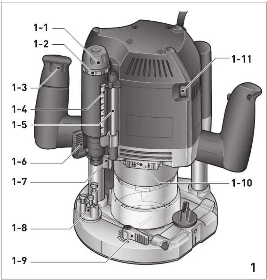
text_image
1-1 1-2 1-3 1-4 1-5 1-6 1-7 1-8 1-9 1-10 1-11 1
text_image
2 2-1 2-2 2-3 2-4 2-5 2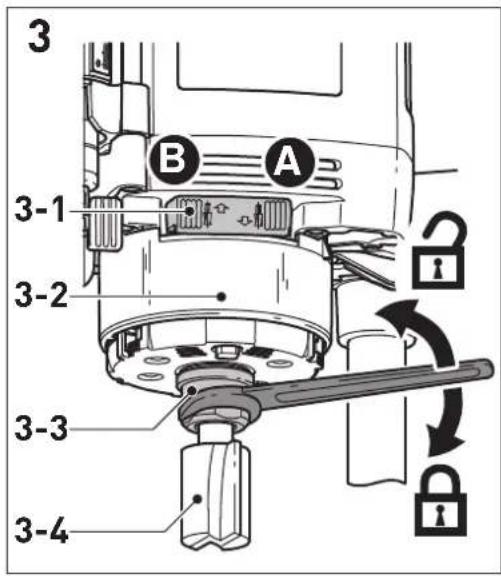
text_image
3 B A 3-1 3-2 3-3 3-4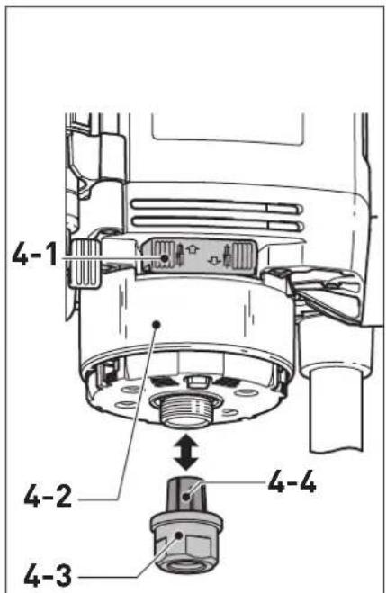
text_image
4-1 4-2 4-3 4-4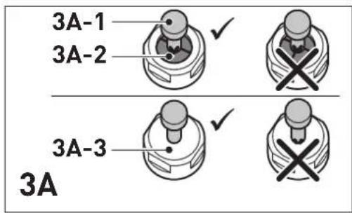
text_image
3A-1 3A-2 3A-3 3A
text_image
4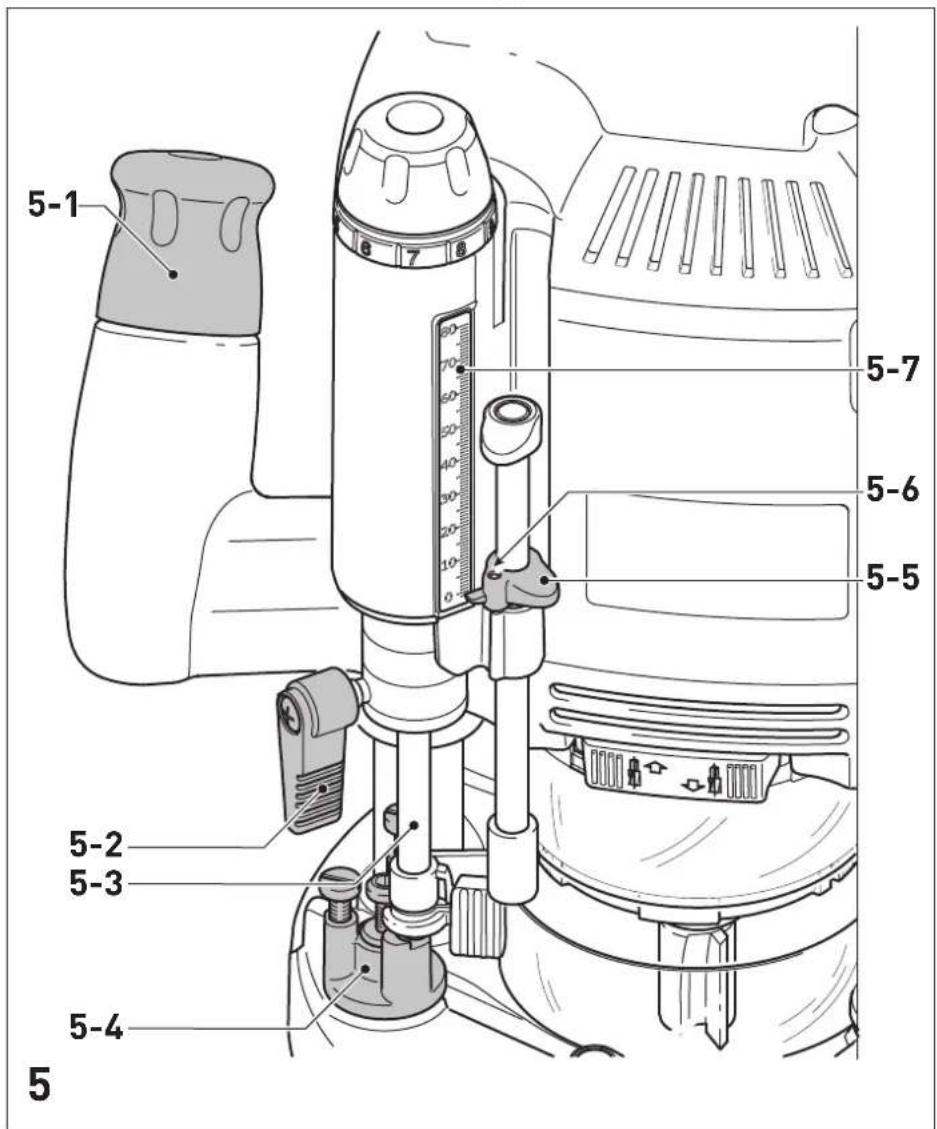
text_image
5-1 5-7 5-6 5-5 5-2 5-3 5-4 5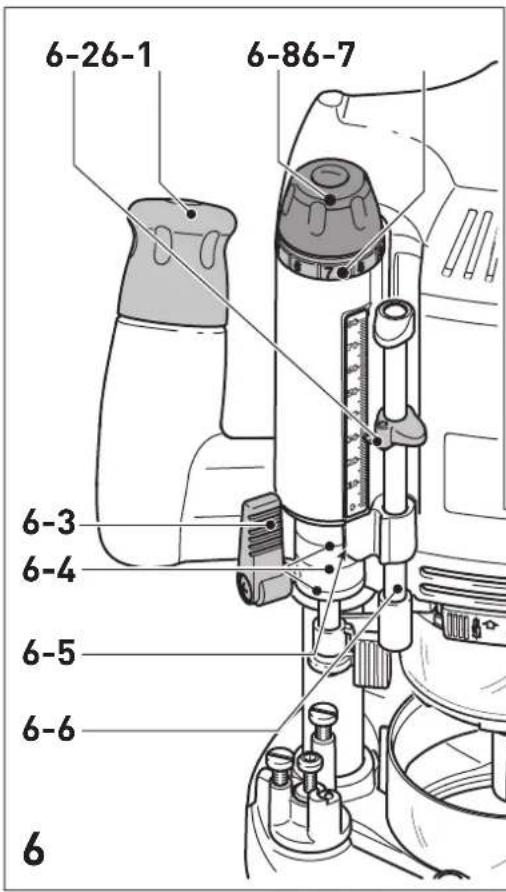
text_image
6-26-1 6-86-7 6-3 6-4 6-5 6-6 6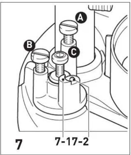
text_image
A B C 7 7-17-2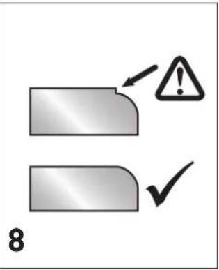
text_image
8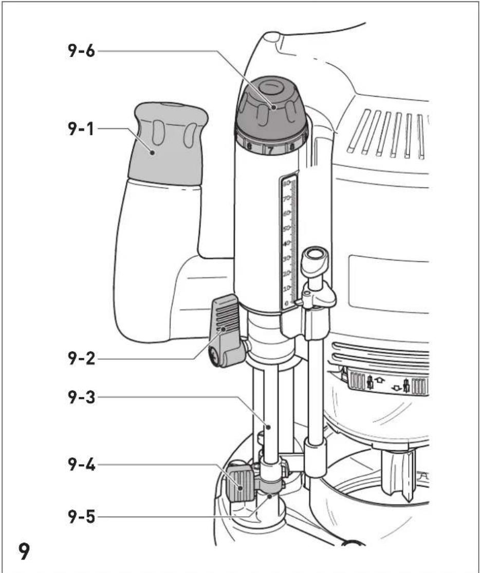
text_image
9-6 9-1 9-2 9-3 9-4 9-5 9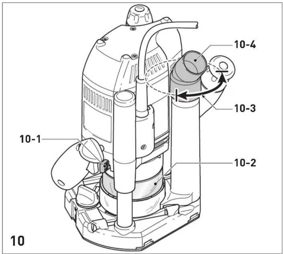
text_image
10 10-1 10-2 10-3 10-4 10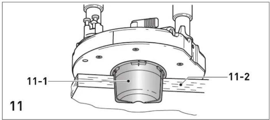
text_image
11-1 11-2 11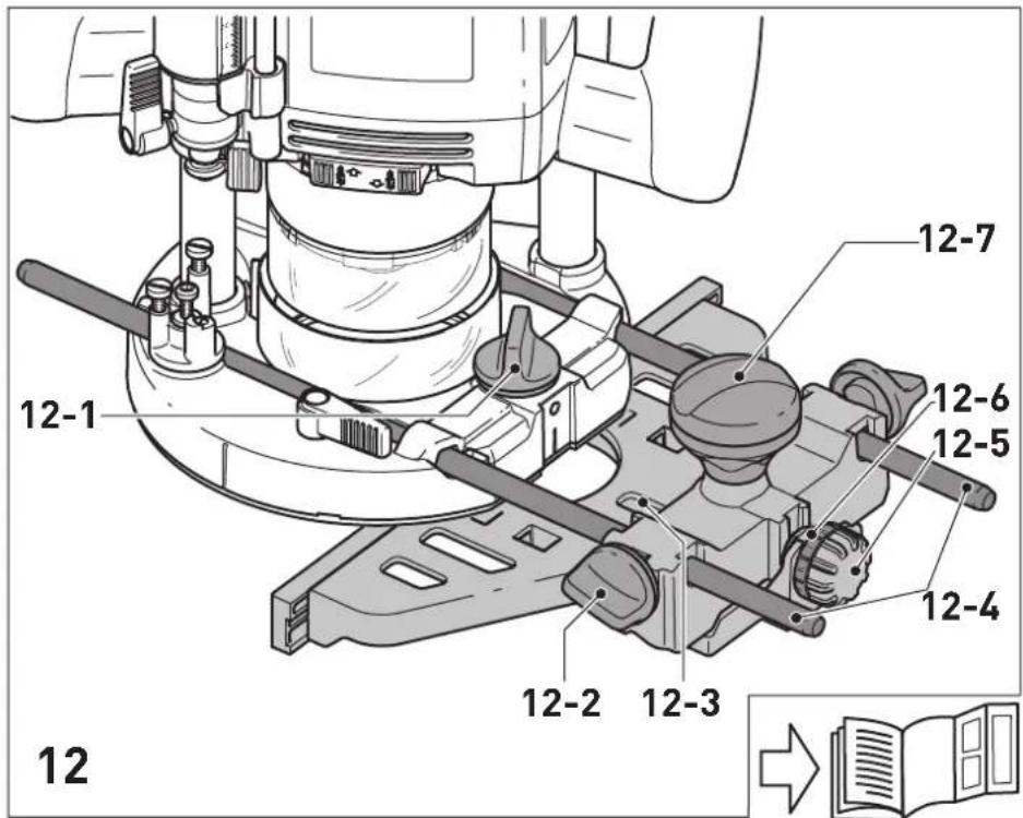
text_image
12 12-1 12-7 12-6 12-5 12-4 12-2 12-3 12Declaration of Conformity
We as the manufacturer Festool GmbH, Wertstraße 20, 73240 Wendlingen, Germany declare under our sole responsibility that the product(s):
Designation:
Designation of Type(s):
Serial number(s) 1):
Router
OF 2200 EB
10477741, 10477848
fulfills all the relevant provisions of the following UK Regulations:
S.I. 2008/1597
S.I. 2016/1091
S.I. 2012/3032
Supply of Machinery (Safety) Regulations 2008
Electromagnetic Compatibility Regulations 2016
Restriction of the Use of Certain Hazardous Substances in Electrical and Electronic Equipment Regulations 2012
and are manufactured in accordance with the following designated standards:
• BS EN 62841-1:2015
• BS EN 62841-2-17:2017
• BS EN 55014-1:2017
• BS EN 55014-2:2015
• BS EN IEC 61000-3-2:2019
• BS EN 61000-3-3:2013
• BS EN IEC 63000:2018
1) in the specified serial number range (S-Nr.) from 400000000 - 499999999

Place and date of declaration: Wendlingen, 07.10.2021
Signed on behalf of and in name of Festool GmbH
Markus Stark
Head of Productdevelopment

text_image
ppa.pssi.V.Q.Brendt
Ralf Brandt
Head of Productconformity
| Oberfräse | Seriennummer * |
| Router | Serial number * |
| Défonceuse | N° de série *(T-Nr.) |
OF 2200 EB 10477741,10477848
de EU-Konformitätserklärung. Wir erklären in alleiniger Verantwortung, dass dieses Produkt mit allen relevanten Anforderungen folgender EU-Richtlinien übereinstimmt, und folgende Normen oder normative Dokumente zugrunde gelegt wurden:
en EU Declaration of Conformity. We declare under sole responsibility that this product complies with all the relevant requirements in the following EU Directives, and following standards and normative documents were applied:
fr Déclaration de conformité de l'UE. Nous déclarons, sous notre seule responsabilité, que ce produit satisfait à toutes les exigences pertinentes des directives UE suivantes et repose sur les normes ou documents normatifs suivants :
es Declaración UE de conformidad. Declaramos bajo nuestra responsabilidad que este producto cumple todos los requisitos relevantes de las siguientes directivas de la UE y que se han tomado como base las siguientes normas o documentos normativos:
it Dichiarazione di conformità UE. Dichiariamo sotto nostra unica responsabilità che il presente prodotto sia conforme a tutti i requisiti di rilevanza definiti dalle seguenti Direttive UE e che siano stati applicati le seguenti norme o i seguenti documenti normativi:
nl EU-conformiteitsverklaring. Wij verklaren en stellen ons ervoor verantwoordelijk dat dit product volledig voldoet aan alle volgende EU-richtlijnen en volgende normen of normatieve documenten daaraan ten grondslag gelegd werden:
SV EU-försäkran om överensstämmelse. Vi för- klarar på eget ansvar att denna produkt uppfyller alla relevanta krav enligt följande EU-direktiv och baseras på följande normer eller normgivande dokument:
fi EU-vaatimustenmukaisuusvakuutus. Vakuutamme yksinomaisella vastuulla, että tämä tuote täyttää seuraavien EU-direktiivien kaikki olennaiset vaatimukset ja se on seuraavien standardien tai standardiasia-kirjojen mukainen:
da EU-overensstemmelseserklæring. Vi erklærer med eneansvar, at dette produkt er i overensstemmel-se med alle relevante krav i følgende EU-direktiver, og at følgende standarder eller normative dokumenter danner grundlag for det:
nb EU-samsvarserklæring. Vi erklærer under eneansvar at dette produktet oppfyller alle relevante krav i følgende EU-direktiver og at følgende standarder eller normative dokumenter er blitt lagt til grunn:
Head of Product Development

text_image
i.v. R B xanottRalf Brandt
Head of Product Conformity
1 Symbols....16
2 Safety warnings....16
3 Intended use 17
4 Technical data.... 17
5 Parts of the device....18
6 Commissioning....18
7 Settings....18
8 Working with the electric power tool......20
9 Service and maintenance....22
10 Accessories.... 22
11 Environment....23
12 General information....23
1 Symbols

Warning of general danger

Warning of electric shock

Read the operating instructions and safety instructions.

Wear ear protection.

Wear protective gloves when changing tools and working with raw materials.

Wear a dust mask.

Wear protective goggles.

Pull out the mains plug

Do not dispose of it with domestic waste.

Safety class II

CE marking: Confirms the conformity of the power tool with the European Community directives.

Tip or advice

Handling instruction

UKCA marking: The United Kingdom Conformity Assessed symbol is a marking for products being placed on the market in the United Kingdom. It is a manufacturers indication that the product is in conformance with the relevant regulations in the UK.
2 Safety warnings
2.1 General power tool safety warnings

WARNING! Read all safety warnings, instructions, illustrations and specifications provided with this power tool. Failure to follow all instructions listed below may result in electric shock, fire and/or serious injury.
Save all warnings and instructions for future reference.
The term "power tool" in the warnings refers to your mains-operated (corded) power tool or battery-operated (cordless) power tool.
2.2 Machine-specific safety notices
- Hold the power tool by insulated gripping surfaces only, because the cutter may contact its own cord. Cutting a "live" wire may make exposed metal parts of the power tool "live" and could give the operator an electric shock.
- Use clamps or another practical way to secure and support the workpiece to a stable platform. Holding the work by your hand or against the body leaves it unstable and may lead to loss of control.
- Only cutters provided by Festool for this purpose may be mounted on the power tool. The use of other cutters is prohibited due to the increased risk of injury.
- The maximum rotational speed specified on the tool must not be exceeded or the rotational speed range must be observed. Accessories that rotate faster than the permissible level can rupture.
- Wait until the power tool has come to a complete halt before placing it down. The insertion tool can get caught and lead to a loss of control of the power tool.
-
In the case of materials to be processed which can become statically charged or lead to static charging, a dissipative overall system consisting of an antistatic suction hose (AS) and extraction mobile must be used.
-
Do not clamp tools with an unsuitable shank diameter in the clamping collet.
- Only use tools that meet standard EN 847-1. All Festool routing tools fulfil these requirements.
- Ensure that the router bit is seated firmly and that it runs perfectly.
- The clamping collet and locking nut must not show any signs of damage
- Do not use cracked or deformed router bits.


Wear suitable personal protective equipment: Ear protection, protective goggles, dust mask for work that generates dust, protective gloves for working with rough materials and for changing tools.
- Only for AS/NZS: The tool shall always be supplied via residual current device with a rated residual current of 30 mA or less.
2.3 Sawing aluminium
When sawing aluminium, the following measures must be taken for safety reasons:
- Install an upstream residual-current circuit breaker (RCD, PRCD).
- Connect the power tool to a suitable dust extractor with an antistatic suction hose.
- Regularly clean dust deposits from the motor housing on the power tool.

- Wear protective goggles.
2.4 Emission levels
The levels determined in accordance with EN 62841 are typically:
Sound pressure level L _PA = 93 dB(A)
Sound power level L _WA = 104 dB(A)
Uncertainty K = 3 dB

CAUTION
Noise generated when working Risk of damage to hearing
▶ Use ear protection.
Vibration emission level a_h (vector sum for three directions) and uncertainty K measured in accordance with EN 62841:
$$ a _ {h} < 2. 5 \mathrm{m} / \mathrm{s} ^ {2} $$
$$ K = 1. 5 \mathrm{m} / \mathrm{s} ^ {2} $$
The specified emission levels (vibration, noise)
- are used to compare machines.
- They are also used for making preliminary estimates regarding vibration and noise load during operation.
- They represent the primary applications of the power tool.
- are used to compare machines. - They are also used for making preliminary estimates regarding vibration and noise load during operation. - They represent the primary applications of the power tool.

CAUTION
The emission values may deviate from the specified values. This is dependent on how the tool is used and the type of workpiece being machined.
▶ The actual load during the entire operating cycle must be evaluated.
▶ Depending on the actual load, suitable protective measures must be defined in order to protect the operator.
3 Intended use
The router is designed for routing wood, plastics and wood-based materials.
If the cutters are used for the intended purpose outlined in the Festool Sales, they may also be used to machine aluminium and plasterboard. This power tool may only be used by experts or instructed persons.

The user is liable for improper or non-in-tended use.
4 Technical data
Router OF 2200 EB
| Power consumption 2200 W* | |
| Speed 10,000- | 22,000 rpm |
| Max. speed (no-load) 23,000 rpm | |
| Quick depth adjustment 80 mm | |
| Fine depth adjustment 20 mm | |
| Drive shaft connecting thread | M22 x 1.0 |
| Cutter diameter Max. 89 mm | |
| Weight as per EPTA procedure 01:2014: | 8.3 kg |
* OF 2200 EB GB 110 V rated current 16 A.
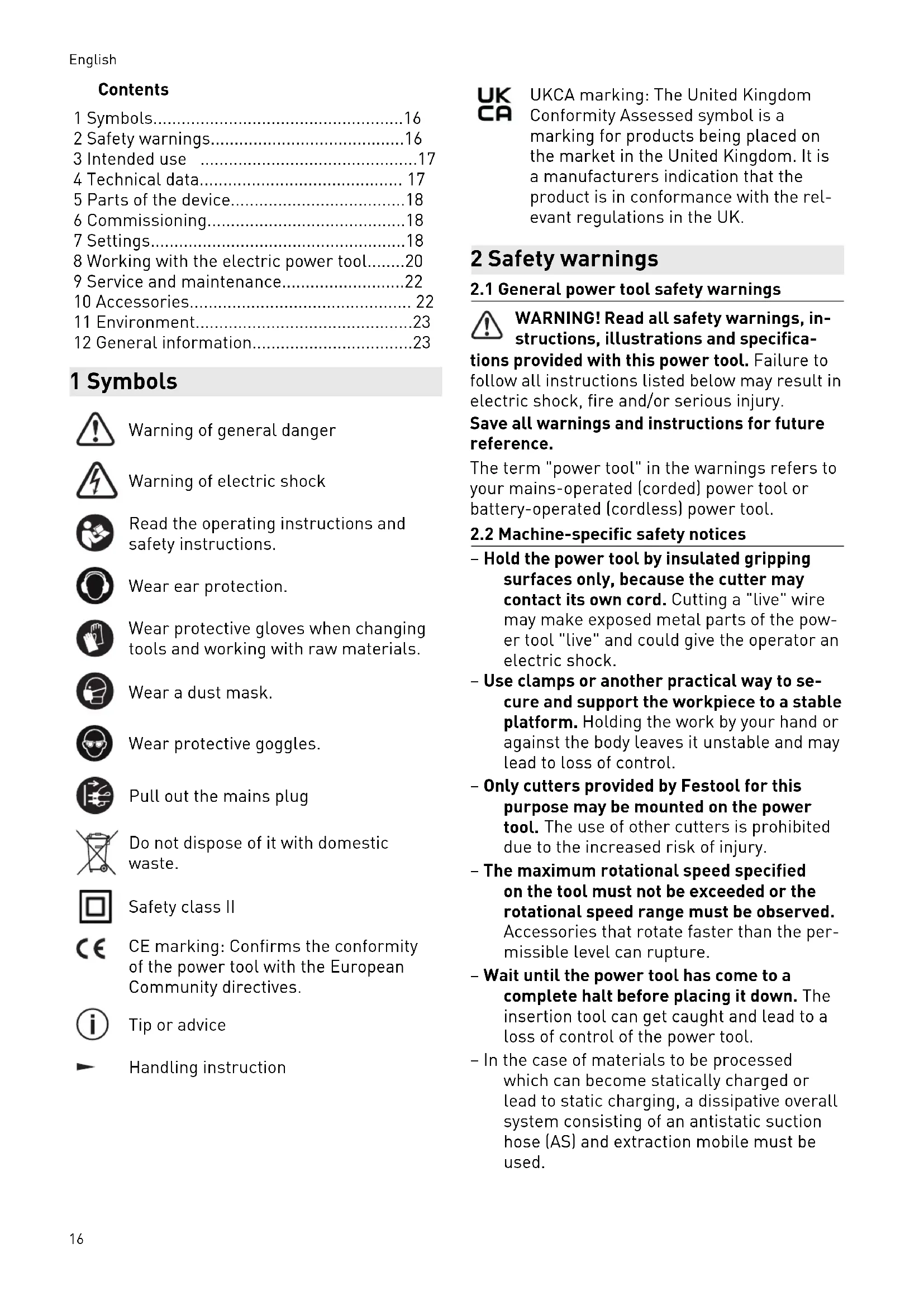
5 Parts of the device
[1-1] Adjusting wheel fine adjuster
[1-2] Fine adjuster scale
[1-3] Height adjustment rotary knob
[1-4] Depth stop scale
[1-5] Depth stop with indicator
[1-6] Depth stop clamp lever
[1-7] Eccentric for coupling the depth stop and the stepped stop
[1-8] Stepped stop
[1-9] Base runner replacement operating lever
[1-10] Spindle stop
[1-11] Speed adjusting wheel
[2-1] On/off switch locking button
[2-2] On/off switch
[2-3] Protective guard locking lever
[2-4] Handles
[2-5] Extractor stub
The illustrations specified are located at the beginning and end of the operating instructions.
Accessories shown or described are not always included in the scope of delivery.
6 Commissioning

WARNING
Unauthorised voltage or frequency.
Risk of accidents
- The mains voltage and the frequency of the power source must correspond to the specifications on the name plate.
▶ In North America, only Festool machines with the voltage specifications 120 V/60 Hz may be used.
6.1 Switching on/off
The switch [2-2] is an on/off switch (press = ON, release = OFF).
The on/off switch with the locking button [2-1] can be engaged to operate in continuous mode. Press the on/off switch again to release the lock.
7 Settings

WARNING
Risk of injury, electric shock
▶ Always disconnect the mains plug from the socket before performing any work on the machine.
7.1 Electronics
Speed control
You can continuously adjust the speed within the speed range using the adjusting wheel [1-11] (see "Technical data").
This enables you to optimise the cutting speed to suit the respective material.
Material Cutter diameter (mm) Recom-
| 10-30 30-50 50-89Adjusting wheel setting | mended cutting material | |
| Hardwood 6-4 5-3 3-1 HW (HSS) | ||
| Soft wood 6-5 6-4 5-3 HSS (HW) | ||
| Coated chipboard | 6-5 6-4 4-2 HW | |
| Plastic 6-4 6-3 3-1 HW | ||
| Aluminium | 3-1 3-1 2-1 HSS (HW) | |
| Plaster-board | 2-1 1 1 HW | |
Temperature cut-out
The power supply is restricted and the speed reduced if the motor exceeds a certain temperature. The power tool continues operating at reduced power to allow the ventilator to cool the motor quickly. The power tool starts up again automatically once the motor has cooled sufficiently.
Restart protection
The built-in restart protection prevents the power tool from starting up again automatically if the power is disconnected when the on/off switch is pressed. In this case, the power tool must be switched off and then switched back on again.
Due to the built-in restart protection, the power tool cannot be switched on and off via an external switch module.
Brake
The OF 2200 EB has an electronic brake which brings the spindle with tool to a standstill within approx. 2 seconds of the tool being switched off.
7.2 Changing tools


CAUTION
Risk of injury from hot and sharp insertion tool
- Do not use any blunt or faulty insertion tools.
- Wear protective gloves when handling an insertion tool.
To change tools, place the power tool on its side.
Only use the spindle stop [3-1] when the power tool is switched off.
Inserting the tool
- Insert the routing tool ([3-4] and [3A-1]) into the open collet [3A-2] as far as possible or at least up to the mark √ on the router shank.
If the collet [3A-2] cannot be seen due to the union nut [3A-3], the routing tool must be inserted into the collet to the extent that the mark ∨ no longer projects beyond the union nut.
▶ Press the switch for the spindle stop [3-1] on the left-hand side [B].
▶ Tighten the union nut [3-3] using an open ended spanner (WAF 24).
The spindle stop only jams the motor spindle in one direction of rotation. Therefore, there is no need to use a spanner for tightening and loosening union nuts. Instead, a ratchet can be moved backwards and forwards.
Removing the tool
▶ Push the chip guard [3-2] upwards until it engages.
▶ Press the switch for the spindle stop [3-1] on the right-hand side [A].
▶ Undo the union nut [3-3] using an open ended spanner (WAF 24) until you can feel resistance. Overcome the resistance by continuing to turn the open ended spanner.
▶ Remove the router.
7.3 Changing the collets
Collets are available for the following shaft diameters: 6.0 mm; 6.35 mm; 8.0 mm; 9.53 mm; 10.0 mm; 12.0 mm; 12.7 mm.
▶ Push the chip guard [4-2] upwards until it engages.
▶ Press the switch for the spindle stop [4-1] on the right-hand side [A].
▶ Completely unscrew the union nut [4-3] and remove it together with the collet [4-4]. Never separate the union nut from the collet as these form a single unit.
▶ Only insert a new collet into the spindle if a union nut is fitted and engaged.
▶ Gently screw in the union nut. Do not tighten the nut if no cutter is inserted.
7.4 Setting the routing depth
The routing depth is set in two steps:
Setting the zero point
▶ Release the clamp lever [5-2] so that the depth stop [5-3] can move freely.
- Position the router on a level surface (reference surface). Open the rotary knob [5-1] and push the power tool downwards until the cutter sits on the surface.
▶ Clamp the power tool in this position by closing the rotary knob [5-1].
▶ Press the depth stop [5-3] against one of the three fixed stops of the rotatable stepped stop [5-4].
▶ Push the indicator [5-5] downwards so that it points to 0 mm on the scale [5-7].
If the zero position is incorrect, this can be corrected using the screw [5-6] on the indicator.
A screwdriver can be used to individually adjust the height of two of the three fixed stops [7] (A and B).
(i) Fixed stop C has a ridge for rough routing – see section 7.5.
Specifying the routing depth
▶ Pull the depth stop [6-6] upwards until the indicator [6-2] points to the required routing depth.
▶ Clamp the depth stop in this position using the clamp lever [6-3].
▶ Open the rotary knob [6-1].
The power tool is now in its initial position.
▶ If necessary, readjust the routing depth by turning the adjusting wheel [6-8].
English
i Turning the adjusting wheel by a mark changes the routing depth by 0.1 mm. A full rotation changes the routing depth by 1 mm.
The scale ring [6-7] can be turned separately so that it can be set to zero.
The three marks [6-4] on the edge [6-5] indicate the maximum adjustment range of the adjusting wheel (20 mm) and the middle position.
7.5 Rough/Precision routing
Fixed stop C has two stop planes with a height difference of 2 mm. This allows users to route workpieces with a routing depth set using stop C in two steps:
Rough routing
▶ Lower the power tool to stop plane [7-1] .
Finishing routing
▶ Lower the power tool to stop plane [7-2] .
i Routing work can be performed as quickly as with a large routing depth while still producing a good surface quality. The final routing depth is determined by the stop plane setting [7-2].
7.6 Fine adjustment for edge trimming
The power tool has a special fine adjuster for using cutters with a ball bearing guide. For example, this makes it quick and easy to set a precise transition when rounding edges without a ridge, see figure [8].
Setting a precise routing depth
▶ First of all, roughly set the routing depth.
▶ Carry out a test rout.
▶ Open the clamping lever [9-2].
▶ Press the depth stop [9-3] against fixed stop C [9-5].
▶ Clamp the depth stop to the turret stop using the eccentric [9-4] (turn clockwise).
▶ Close the clamping lever [9-2] .
▶ Open the rotary knob [9-1] .
▶ Precisely adjust the routing depth by turning the adjusting wheel [9-6].
① It is possible to adjust the routing depth in both directions thanks to the coupling between the depth stop and the turret stop.
▶ Close the rotary knob [9-1] .
▶ Open the eccentric [9-4] (turn anticlockwise).
▶ If necessary, carry out additional test routes and adjust the settings.
7.7 Dust extraction


WARNING
Health hazard posed by dust
▶ Always work with an extractor.
▶ Only work with a fully functional chip guard [10-2].
▶ Always wear a dust mask when performing work that generates dust.
▶ Comply with national regulations.
A Festool dust extractor with an extractor hose diameter of 36 mm or 27 mm (36 mm recommended due to the reduced risk of clogging) can be connected to the extractor connector [10-4].
Insert the extractor connector [10-4] as in image [10]. The extractor connector can be turned in the area of [10-3].
CAUTION! If an anti-static suction hose is not used, static charge may occur. The user may receive an electric shock and the electronics of the power tool may be damaged.
Chip guard
The chip guard [10-2] can be engaged in an upper position, e.g. for cutter changes.
▶ Slide the chip guard upwards until it engages or push the power tool downwards until it reaches the limit stop.
To improve the efficiency of the dust extraction, lower the chip guard while working.
- Press the lever [10-1] in the direction of the handle.
Chip deflector KSF-OF
The chip deflector KSF-OF [11-1] (available as an accessory depending on the model) can improve the efficiency of the dust extraction system when edge routing. The maximum cutter diameter is 78 mm.
The chip deflector is installed in the same way as inserting the copying ring, see section 8.3.
A hacksaw can be used to cut along the grooves [11-2] of the guard and therefore make it smaller. The chip deflector can then be used for inner radii down to a minimum radius of 52 mm.
8 Working with the electric power tool

When working on the machine, observe all of the safety warnings that are listed at the start as well as the following rules:
- Only guide the power tool towards the workpiece when it is switched on.
- Ensure that the clamping lever [1-6] is closed and the eccentric [1-7] is open before starting work.
- Always secure the workpiece in such a way that it cannot move during machining.
- When working, always hold the power tool with both hands on the handles [2-4]. This is a prerequisite for precise work and is essential for plunge-cutting.
- When routing, ensure that the power tool's feed direction is the same as the tool's cutting direction, see figure [15].
8.1 Routing
▶ Set the required routing depth, see section 7.4.
▶ Switch on the power tool.
▶ Open the rotary knob [1-3] .
▶ Push the power tool downwards until it reaches the limit stop.
▶ Clamp the power tool in this position by closing the rotary knob [1-3].
- Plunge into the workpiece slowly and evenly.
▶ Perform the routing work.
▶ Open the rotary knob [1-3].
▶ Slowly move the power tool upwards until it reaches the limit stop (lift it out).
▶ Switch off the power tool.
8.2 Routing with a parallel side fence
The parallel side fence (available as an accessory depending on the model) is used in parallel with the workpiece edge for routing work.
- Clamp the two guide rods [12-4] to the parallel side fence using the two rotary knobs [12-2].
▶ Insert the guide rods into the grooves of the router table to the required extent and clamp them using the rotary knob [12-1].
Fine adjustment
▶ Open the rotary knob [12-7] to make a fine adjustment using the adjusting wheel [12-5].
The scale ring [12-6] has a 0.1 mm scale for this purpose. If the adjusting wheel is held, the scale ring can be turned separately so that it can be set to zero. The scale [12-3] displays the adjustment in millimetres.
▶ Close the rotary knob [12-7] after making a fine adjustment.
▶ Set the two guidance jaws [13-3] so that they are approx. 5 mm from the cutter. To
do this, loosen the screws [13-2] and re-tighten them after making an adjustment.
For edge routing only: Push the dust-extraction attachment [13-1] from behind until it engages on the parallel side fence and connect an extractor hose with a diameter of 27 mm or 36 mm to the extractor connector [13-4]. Alternatively, leave the extractor hose on the power tool's extractor connector.
8.3 Copy routing
A router with a fitted copying ring (available as an accessory) should be used for routing work with templates.
The copying rings can be used with the base runner supplied as standard. A special base runner for workpiece support surface improvement is available as an accessory.
Inserting the copying ring

CAUTION
Risk of accidents
Using a cutter that is too large may damage the copying ring and cause accidents.
▶ Ensure that the cutter being used fits through the opening of the copying ring.
▶ Lay the power tool on its side on a stable base.
▶ Release the lever [14-4].
▶ Remove the base runner [14-1].
▶ Release the lever [14-4] again.
▶ Insert the copying ring[14-3] into the router table in the correct position.
▶ Insert the base runner with the tabs [14-2] into the router table.
▶ Push the base runner into the router table until it engages.
Excess Y (figure [15]) of the workpiece to the template is calculated as follows:
Y = (copying ring diameter - cutter diameter)/2
8.4 Edge trimming
The cutters with a ball bearing guide are inserted into the power tool for edge trimming. The power tool is guided in such a way that the ball bearing guide rolls on the workpiece.
When edge trimming, always use the chip deflector KSF-OF to improve dust extraction.
8.5 Routing with the FS guide system
The guide system (available as an accessory depending on the model) makes it easier to route straight grooves.
▶ Secure the guide rail to the workpiece using fastening clamps [16-4].
▶ Insert the base runner [16-3] for the guide rail adapter into the router table of the router (see section 8.6). This base runner has a ridge which adjusts to the height of the guide rail.
▶ Clamp the two guide rods [16-6] on the guide rail adapter using the rotary knobs [16-5] and [16-9].
▶ Open the rotary knob [16-1]
▶ Insert the guide rods [16-6] into the grooves of the router table.
▶ Place the router with the guide rail adapter on the guide rail.
▶ If necessary, use a screwdriver on the two guidance jaws [16-2] to adjust the play between the guide rail adapter and the guide rail.
▶ Move the router along the guide rods until there is the required distance between the cutter and the guide rail. Ensure that there is a safety distance X of (see figure [16]) 5 mm between the front edge of the guide rail and the cutter, or the groove.
▶ Close the rotary knob [16-1].
▶ Open the rotary knob [16-10].
▶ Precisely adjust distance X by turning the adjusting wheel [16-7]. Hold the adjusting wheel [16-7] to separately turn the scale [16-8] and set it to zero.
▶ Close the rotary knob [16-10]
8.6 Changing the base runner
Festool offers special base runners (available as an accessory) for different applications.
▶ Lay the power tool on its side on a stable base.
▶ Release the lever [14-4].
▶ Remove the base runner [14-1].
▶ Release the lever [14-4] again.
▶ Insert the base runner with the tabs [14-2] into the router table.
▶ Push the base runner into the router table until it engages.
When using the base runner for the first time: Remove the protective film.
9 Service and maintenance

WARNING
Risk of injury, electric shock
▶ Always pull the mains plug from the socket before performing any servicing and main tenance work.
▶ All maintenance and repair work which requires the housing to be opened should always be carried out by an authorised service workshop.

Customer service and repairs must only be carried out by the manufacturer or service workshops. Find the nearest address at: www.festool.co.uk/service
Always use original Festool spare parts. Order no. at: www.festool.co.uk/service
The tool is equipped with special self-disconnecting carbon brushes. If they wear out, the power supply is disconnected automatically and the tool stops.
Observe the following instructions:
▶ If it is necessary to replace the mains power cable of the power tool, this must be replaced by the manufacturer or an authorised service workshop, so as to avoid safety hazards.
▶ Damaged safety devices and components must be repaired or replaced in a recognised specialist workshop, unless otherwise indicated in the operating instructions.
▶ To ensure constant air circulation, always keep the cooling air openings in the housing clean and free of blockages.
10 Accessories
Always use original Festool tools and accesso-
ries. Using low-quality tools or accessories from other manufacturers may increase the risk of injury and seriously unbalance the machine, decreasing the quality of the working results and accelerating power tool wear.
Refer to the Festool catalogue for the order numbers of accessories and tools or find them online at www.festool.co.uk.
11 Environment

Do not dispose of the device in the household waste! Recycle devices, accessories and packaging. Observe applicable national regulations.
EU only: In accordance with the European Directive on waste electrical and electronic equipment and implementation in national law, used power tools must be collected separately and handed in for environmentally friendly recycling.
Information on REACH: www.festool.com/reach
12 General information
Imported into the UK by
Festool UK Ltd
1 Anglo Saxon Way
Bury St Edmunds
IP30 9XH
Great Britain
Sommaire
Aluminium 3 - 1 3 - 1 2-1 HSS (HW)
Gipskarton 2 - 1 1 1 HW
Temperatursikring
| Mykved 6 - 5 6 - 4 5 - 3 HSS (HW) |
| Sponpla-ter, be-lagt | 6 - 5 6 - 4 4 - 2 HW |
| Plast 6 - 4 6 - 3 3 - 1 HW |
| Aluminium | 3 - 1 | 3 - 1 | 2-1 | HSS (HW) |
| Gipsplate 2 - 1 1 1 | HW |
Temperatursikring
7.6 Fininnstilling for kantbearbeiding
natural_image
Mechanical diagram showing a rotating shaft and flange assembly with dimension lines (no text or symbols)16-1
16-10
16-9
16-8
16-7
16-6
16-5
16-2
x
16-4
16-3
16