PF 1200 EPlus - Milling machine FESTOOL - Free user manual and instructions
Find the device manual for free PF 1200 EPlus FESTOOL in PDF.

| Brand | Festool |
| Model | PF 1200 EPlus |
| Product type | Aluminum plate router |
| Power | 1200 W |
| No-load speed | 2000 - 5700 rpm |
| Cutter outer diameter | 118 mm |
| Bore diameter | 20 mm |
| Cutter width | 14 mm |
| Weight (according to EPTA 01:2015) | 5.4 kg |
| Power supply | 230 V mains |
| Protection class | II |
| Dust extraction connection | Sleeve 36 mm |
| Speed adjustment | Continuous dial 2000-5700 rpm |
| Electronic functions | Soft start, speed regulation, constant speed, thermal protection |
| Cutting depth | Adjustable via rotary stop for plates of 3, 4 or 6 mm |
| Feeler disc | Interchangeable for different thicknesses |
| Guide rail | Mandatory, fixation with clamps |
| Sound pressure level | 88 dB(A) |
| Sound power level | 99 dB(A) |
| Vibration (milling Dibond®) | < 2.5 m/s² |
| Maintenance | Regular cleaning, automatic cut-off carbon brushes |
| Safety | Start lock, protective cover, emergency stop |
| Intended use | Grooving of aluminum/plastic composite plates (Alucubond®, Dibond®) |
| Original accessories | Festool cutter and feeler disc |
Frequently Asked Questions - PF 1200 EPlus FESTOOL
User questions about PF 1200 EPlus FESTOOL
0 question about this device. Answer the ones you know or ask your own.
Ask a new question about this device
Download the instructions for your Milling machine in PDF format for free! Find your manual PF 1200 EPlus - FESTOOL and take your electronic device back in hand. On this page are published all the documents necessary for the use of your device. PF 1200 EPlus by FESTOOL.
USER MANUAL PF 1200 EPlus FESTOOL
natural_image
Close-up of a black FESTOOL power tool with visible blade and handle (no text or symbols on the device itself)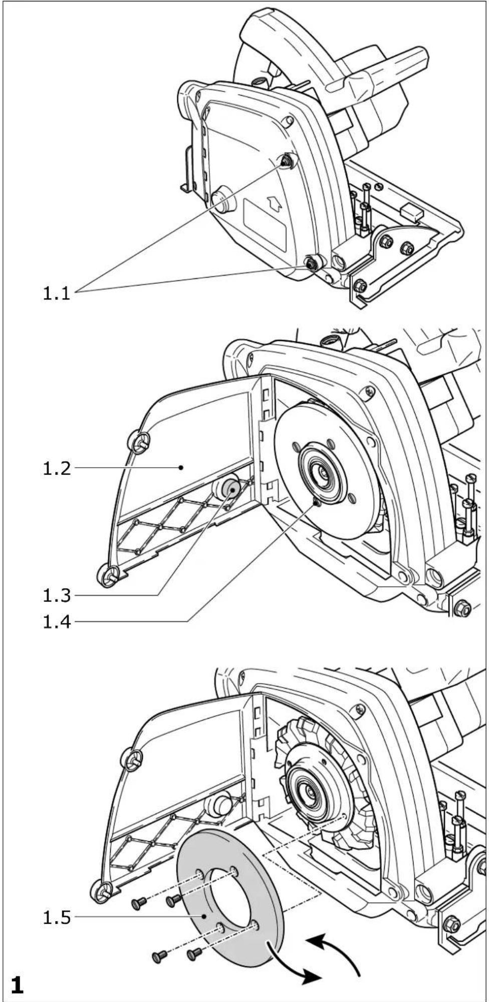
text_image
Warning symbol and three mechanical hazard icons: triangular warning triangle, gear with clockwise arrow, and hand crossed with cross2
text_image
3.1 3.2 min. 150 mm min. 150 mm 3.3 3.4 3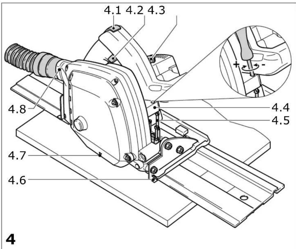
text_image
4.1 4.2 4.3 4.8 4.7 4.6 4.4 4.5 4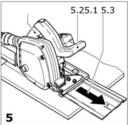
text_image
5.25.1 5.3 5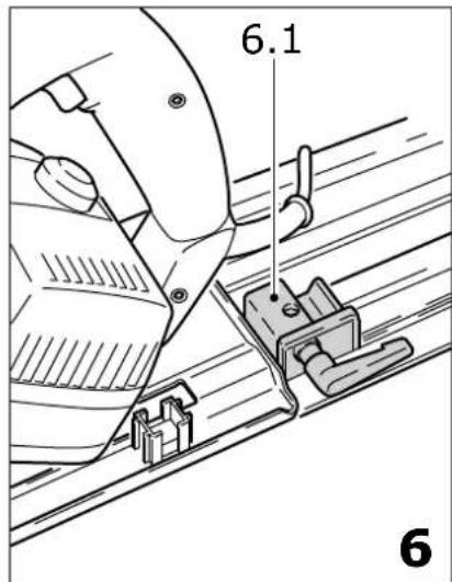
text_image
6.1 6| Plattenfräse | Seriennummer * |
| Aluminium composite milling machine | Serial number *N° de série *(T-Nr.) |
| Fraiseuse de plaque aluminium |
PF 1200 E 491279, 491663
de EG-Konformitätserklärung. Wir erklären in alleiniger Verantwortung, dass dieses Produkt allen ein-schlägigen Bestimmungen der folgenden Richtlinien einschließlich ihrer Änderungen entspricht und mit den folgenden Normen übereinstimmt:
en EC-Declaration of Conformity. We declare under our sole responsibility that this product is in conformity with all relevant provisions of the following directives including their amendments and complies with the following standards:
fr CE-Déclaration de conformité communautaire. Nous déclarons sous notre propre responsabilité que ce produit est conforme aux normes ou documents de normalisation suivants:
es CE-Declaración de conformidad. Declaramos bajo nuestra exclusiva responsabilidad que este producto corresponde a las siguientes normas o documentos normalizados:
it CE-Dichiarazione di conformità. Dichiariamo sotto la nostra esclusiva responsabilità che il presente prodotto e conforme alle norme e ai documenti normativi seguenti:
nl EG-conformiteitsverklaring. Wij verklaren op eigen verantwoordelijkheid dat dit produkt voldoet aan de volgende normen of normatieve documenten:
sv EG-konformitetsförklaring. Vi förklarar i eget ansvar, att denna produkt stämmer överens med följande normer och normativa dokument:
fi EY-standardinmukaisuusvakuutus. Va-kuutamme yksinvastuullisina, etta tuote on seuraavien standardien ja normatiivisten ohjeiden mukainen:
da EF-konformitetserklæring Vi erklærer at have alene ansvaret for, at dette produkt er i overensstemmelse med de følgende normer eller normative dokumenter:
nb CE-Konformitetserklæring Vi erklærer på eget ansvar at dette produktet er i overensstemmelse med følgende normer eller normative dokumenter:
Markus Stark Head of Product Development
text_image
i.V. R B xanckRalf Brandt Head of Product Conformity
- outside diameter 118 mm
- drill hole diameter 20 mm
- width 14 mm
Weight according to
EPTA-Procedure 01:2015 5.4 kg
The specified illustrations can be found at the beginning of the operating instructions.
1 Graphical symbols

Caution. Danger!

Read the operating instructions/notes

Wear ear protection!

Wear protective goggles!

Wear a protective mask!

Safety class II
2 Safety warnings
2.1 General power tool safety warnings

WARNING! Read all safety warnings, instructions, illustrations and specifications provided with this power tool. Failure to follow all instructions listed below may result in electric shock, fire and/or serious injury.
Save all warnings and instructions for future reference.
The term „power tool“ in the warnings refers to your mains-operated (corded) power tool or battery-operated (cordless) power tool.
2.2 Tool-specific safety warnings for milling tools
Milling procedures
a)

DANGER! Keep hands away from cutting area and the milling tool. Keep your second hand on auxiliary handle, or motor housing. If both hands are holding the milling tool, they cannot be cut by the tool.
b) Do not reach underneath the workpiece. The guard cannot protect you from the tool below the workpiece.
c) Adjust the milling depth to the thickness of the workpiece. Less than a full tooth of the tool should be visible below the workpiece.
d) Never hold the workpiece in your hands or across your leg while milling. Secure the workpiece to a stable platform. It is important to support the work properly to minimize body exposure, binding, or loss of control.
e) Hold the power tool by insulated gripping surfaces, when performing an operation where the milling tool may contact hidden wiring or its own cord. Contact with a „live“ wire will also make exposed metal parts of the power tool „live“ and could give the operator an electric shock.
f) When milling, always use a straight edge guide. This improves the accuracy of cut and reduces the chance of binding.
g) Always use mounting tools with correct size and shape (diamond versus round) of arbour holes. Tools that do not match the mounting hardware of the milling tool will run eccentrically, causing loss of control.
h) Never use damaged or incorrect blade washers or bolt. The washers and bolt were specially designed for your milling tool, for optimum performance and safety of operation.
Kickback causes and related warnings
- kickback is a sudden reaction to a pinched, bound or misaligned mounting tool, causing an uncontrolled milling tool to lift up and out of the workpiece toward the operator;
- when the milling tool is pinched or jammed tightly by the kerf closing down, the milling tool stalls and the motor reaction drives the unit rapidly back toward the operator;
- if the milling tool becomes twisted or misaligned in the groove, the teeth at the back edge of the milling tool can dig into the top surface of the material causing the milling tool to climb out of the kerf and jump back toward the operator.
Kickback is the result of misuse and/or incorrect operating procedures or conditions and can be avoided by taking proper precautions as given below.
a) Maintain a firm grip with both hands on the milling tool and position your arms to resist kickback forces. Position your body to either
side of the tool, but not in line with the tool. Kickback could cause the milling tool to jump backwards, but kickback forces can be controlled by the operator, if proper precautions are taken.
b) When the tool is binding, or when interrupting a cut for any reason, release the trigger and hold the tool motionless in the material until the tool comes to a complete stop. Never attempt to remove the milling tool from the work or pull the milling tool backward while the tool is in motion or kickback may occur. Investigate and take corrective actions to eliminate the cause of binding.
c) When restarting a milling tool in the workpiece, centre the tool in the kerf so that the tool teeth are not engaged into the material. If a tool binds, it may walk up or kickback from the workpiece as the milling tool is restarted.
d) Support large panels to minimise the risk of pinching and kickback. Large panels tend to sag under their own weight. Supports must be placed under the panel on both sides, near the line of cut and near the edge of the panel.
e) Do not use dull or damaged tools. Unsharpened or improperly set tools produce narrow kerfs causing excessive friction, binding and kickback.
f) Tool depth and bevel adjusting locking levers must be tight and secure before milling. If tool adjustment shifts while milling, it may cause binding and kickback.
g) Use extra caution when milling into existing walls or other blind areas. The protruding tool may cut objects that can cause kickback.
Function of the lower guard
a) Check the function of the springs for the lower guard. If the lower guard or springs show any signs of a defect, have the milling tool serviced before using it again. Damaged parts, sticky deposits or accumulated chips may result in delayed operation of the lower guard.
2.3 Further safety warnings


Wear suitable protective equipment such as ear protection, safety goggles, a dust mask for work which generates dust, and protective gloves when working with raw materials and when
changing tools.
- This electric power tool cannot be installed in a work bench. The electric power tool may
become unsafe and cause serious accidents if installed in benches from other manufacturers or self-manufactured work benches.
- Never place your hands into the chip ejector. You may injure yourself on rotating parts.
- Wait until the power tool stops completely until placing it down. The tool can become entangled and lead to a loss of control of the power tool.
- Ensure that the milling tool is firmly seated and check that it runs smoothly.
- Do not use the tool for overhead work.
- Harmful/toxic dust may be produced during your work (e.g. paint containing lead, certain types of wood and metal). Inhaling or coming into contact with this dust may represent a hazard for operating personnel or persons in the vicinity. Comply with the safety regulations that apply in your country. Ensure that enclosed spaces are adequately ventilated.
2.4 Noise and vibration information
Typically, the noise levels that are determined in accordance with EN 62841 (see EC declaration of conformity) are as follows:
| Sound-pressure level L | _PA = 88 dB(A) |
| Sound-power level L | _WA = 99 dB(A) |
| Uncertainty K = 3 dB |

Wear ear protection!
Vibration emission value a_h (vector sum for three directions) and uncertainty K measured in accordance with EN 62841 (see EU Declaration of Conformity):
| Routing a Dibond® panel a | _h = <2.5 m/s^2 |
| K = 1.5 m/s ^2 |
The specified emissions values (vibration, noise) – are used to compare machines.
- They are also used for making preliminary estimates regarding vibration and noise loads during operation.
- They represent the primary applications of the power tool.

CAUTION
noise emissions during actual use of the power tool can differ from the declared values depending on the ways in which the tool is used especially what kind of workpiece is processed.
Identify safety measures to protect the operator that are based on an estimation of exposure in the actual conditions of use (taking account of all parts of the operating cycle such as the times when the tool is switched off and when it is running idle in addition to the trigger time).
3 Intended use
The PF 1200 E is used to route grooves into composite plates made from aluminium, plastic (Alucubond®, Dibond®).
Only use power tools with attached dust extractor. Only insert milling tools with the correct dimensions.
Do not use abrasive discs.
Only a Festool routing tool in accordance with EN 847-1 may be used.
Only rout materials for which the router has been designed.
This power tool may only be used by experts or instructed persons.

The user is liable for damage and accidents caused by improper and non-intended use.
4 Power supply and start-up

The mains voltage must correspond to the specification on the rating plate.
Switch (4.2) serves as an On/Off switch (press = ON, release = OFF). The switch can only be activated after the switch lock (4.1) has been pushed up.
Activating the switch lock simultaneously locks the plunging equipment and the milling unit can be moved down against the spring force. This causes the milling tool to emerge from the protective cover.

Only guide the tool against the workpiece when it is switched on.
When the tool is lifted, the milling unit springs back into the starting position.
5 Tool settings

Always remove the power supply plug from the socket before carrying out any work on the tool.
5.1 Sensor
The sensor remains on the workpiece while it is being routed. Its function is to determine the cutting depth. Festool offers sensors for all the usual plate thicknesses.
Changing the sensor
- Press the screws (1.1) and turn them to the left.
- Open the flap (1.2).
- Unscrew the four screws (1.4).
- Replace the jockey roller (1.5).
- Tighten the four screws (1.4).
- Close the flap (1.2).
- Press the screws (1.1) and turn them to the right until they latch into place.
5.2 Depth stop (4.5)
When the sensor is on the workpiece, i.e. in working position, there must be a gap of 0.3 mm between the depth stop (4.5) and the stop plate (4.4). This limits the cutting depth, and prevents the tool from tilting to the side while work is in progress. This would happen if one side of the tool moved away from the guide rail.
Use a screwdriver to adjust the three screws on the rotating depth stop. The screws have been set for plate thickness of 3 mm, 4 mm and 6 mm in the factory.
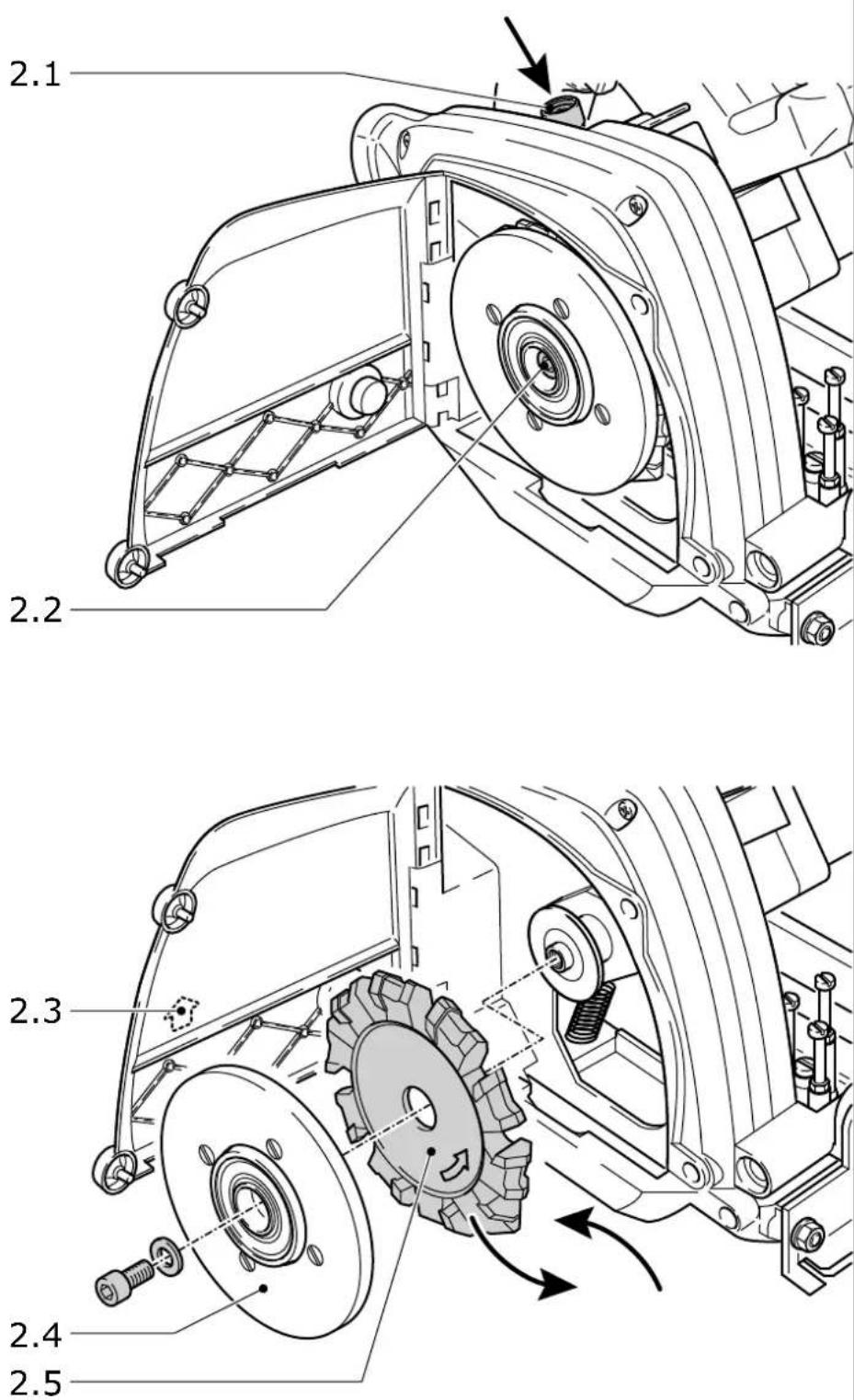
5.3 Changing tools
- Press the screws (1.1) and turn them to the left.
- Open the flap (1.2).
- Press the spindle stop (2.1) and turn the tool (2.4) until the spindle stop latches into place; keep the spindle stop pressed in.
- Open the screw (2.2).
- Remove the tool (2.5) and sensor (2.4).
- Clean the contact surface between the tool flange, the tool, and the sensor; insert the new tool with the sensor.

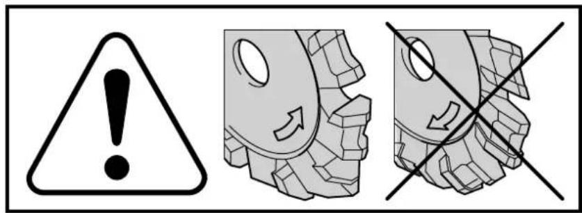
The direction of rotation on the tool must be the same as the direction of rotation of the tool (2.3).
- Tighten the screw (2.2) and let go of the spindle stop
- Close the flap (1.2).
- Press the screws (1.1) and turn them to the right until they latch into place.
5.4 Dust extraction

Always connect the tool to a dust extractor.
You can connect a Festool extractor with an extractor hose diameter of 36 mm to the extractor connector (4.8).
6 Electronics

The PF 1200 E features full-wave electronics with the following properties:
Smooth start-up
The smooth start-up ensures the milling tool starts up jolt-free.
Speed adjustment
You can regulate the speed steplessly between 2000 and 5700 min ^-1 using the adjusting wheel (4.3). We recommend the following position in the adjusting wheel (4.3): 5-6.
Constant speed
The pre-selected speed remains constant whether the tool is in operation or in neutral position.
Temperature control
To prevent overheating, the safety electronics switches the tool off when it reaches a critical motor temperature. Let the tool cool down for approx. 3-5 minutes before using it again. The tool requires less time to cool down if it is running, i.e. in neutral position.
7 Working with the tool

Always secure the workpiece in such a manner that it cannot move while being cut.

The tool must always be held with both hands by the designated handles (5.1, 5.2).

Always push the tool forwards (5.3), never pull the tool backwards towards you.

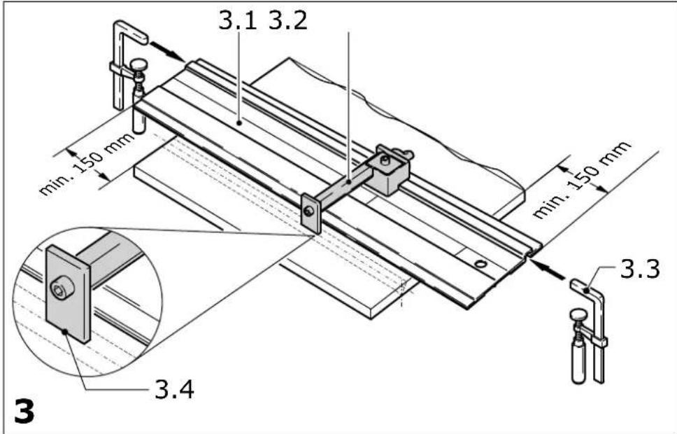
You can use the milling tool only in connection with the guide rail (3.1).
Attach the guide rail to the workpiece as follows
- The guide rail must extend at least 150 mm beyond either end of the workpiece.
- Align the guide rail using the gauge mark (3.2). The front edge (3.4) shows the centre of the groove.
- Secure both sides of the guide rail to the workpiece using two clamps (3.3).
Metalworking

The following precautions are to be taken when processing metals for safety reasons:
- Pre-connect a residual current circuit-breaker (FI, PRCD).
- Connect the tool to a suitable dust extractor.
- Clean tool regularly of dust accumulations in the motor housing.

Wear protective goggles.
Route the groove as follows
- Ensure that the sensor and depth stop are correctly set for the workpiece thickness.
- Place the tool on the guide rail in front of the edge of the workpiece. The mark (4.7) shows the centre axis of the milling tool.
- Switch on the tool.
- Move the tool downwards slowly until the stop plate (4.4) is resting on the depth stop (4.5).
- Move the tool forward along the guide rail in order to route the groove. The gauge mark (4.6) shows the centre of the groove.
- When the groove is complete, switch the tool off and swivel it upwards.
Plunge-cut

In the case of plunge cuts, a guide limiter (6.1) must be attached behind the tool because of the danger of kickbacks. Position the tool on the guide limiter, hold securely with both hands and move it downwards very slowly.
8 Maintenance and care

Always remove the power supply plug from the socket before carrying out any work on the tool.

All maintenance and repair work which requires the motor casing to be opened may only be carried out by an authorised service centre.
Always keep the tool and the ventilation slots clean.
The tool is fitted with special motor brushes with an automatic cut-out. When the brushes become worn the power supply is shut off automatically and the tool comes to a standstill.
A brake disc (1.3) decelerates the sensor to prevent it from being accelerated by the rotating tool and leaving marks behind on the workpiece. Replace the brake disc if its power decreases.

Customer service and repair. Only through manufacturer or service workshops: Please find the nearest address at: www.festool.com/service

Use only original Festool spare parts! Order No. at: www.festool.com/service
9 Accessories, tools

For your own safety, use only original Festool accessories and Festool consumable material intended for this tool.
Because these components are designed specifically for the tool. Using accessories and consumable material from other suppliers will most likely affect the quality of your working results and limit any warranty claims. Tool wear or your own personal workload may increase depending on the application. Protect yourself and your tool, and preserve your warranty claims by always using original Festool accessories and Festool consumable material!
The order numbers of the accessories and tools can be found in the Festool catalogue or on the Internet under "www.festool.com".
10 Environment
Do not throw the power tool in your household waste! Dispose of tools, accessories and packaging at an environmentally-responsible recycling centre. Observe the valid national regulations.
EU only: In accordance with European Directive on waste electrical and electronic equipment and implementation in national law, used electric power tools must be collected separately and handed in for environmentally friendly recycling.
Information on REACH:
www.festool.com/reach