MFK 700 EQ - Milling machine FESTOOL - Free user manual and instructions
Find the device manual for free MFK 700 EQ FESTOOL in PDF.
| Product type | Modular router (plunge router) |
| Brand | FESTOOL |
| Model | MFK 700 EQ |
| Power consumption | 720 W |
| No-load speed | 10,000 - 26,000 min⁻¹ |
| Tool holder (collet chuck) | 8 mm (option: 6 mm, 1/4") |
| Max. cutter diameter | 26 mm (1") |
| Dust extraction connection | 27 mm |
| Weight | 1.9 kg |
| Protection class | I (grounded) |
| Included router tables | Large surface + for edge banding (SET version) |
| Side fence | With guide rods and fine adjustment |
| Soft start | Yes, electronic |
| Speed control | Continuous via thumbwheel |
| Constant speed maintenance | Yes, under load |
| Thermal protection | Automatic shut-off in case of overheating |
| Sound pressure level | LPA = 78 dB(A) |
| Sound power level | LWA = 89 dB(A) |
| Vibration value (triaxial) | a_b = 3.0 m/s² |
| Workable materials | Wood, plastics, aluminium |
| Compatible accessories | Original Festool |
| Warranty | 24 months (EU), 12 months minimum |
Frequently Asked Questions - MFK 700 EQ FESTOOL
User questions about MFK 700 EQ FESTOOL
0 question about this device. Answer the ones you know or ask your own.
Ask a new question about this device
Download the instructions for your Milling machine in PDF format for free! Find your manual MFK 700 EQ - FESTOOL and take your electronic device back in hand. On this page are published all the documents necessary for the use of your device. MFK 700 EQ by FESTOOL.
USER MANUAL MFK 700 EQ FESTOOL
Modular router MFK 700 EQ
Table of contents
1 Symbols
2 Technical data
3 Scope of delivery
4 Intended use
5 Safety instructions
5.1 General safety instructions
5.2 Machine-related safety instructions
5.3 Emission levels
6 Commissioning
7 Machine settings
7.1 Electronics
7.2 Changing the router table
7.3 Changing the routing tool
7.4 Changing the clamping collet
7.5 Adjusting the routing depth
7.6 Dust extraction
8 Working with the machine
8.1 Machine guidance methods
8.2 Aluminium processing
9 Service and maintenance
10 Accessories, tools
11 Disposal
12 Warranty
13 EU Declaration of Conformity
The specified illustrations can be found at the beginning an at the end of the operating instructions. The spare parts list appears at the end of this operating manual.
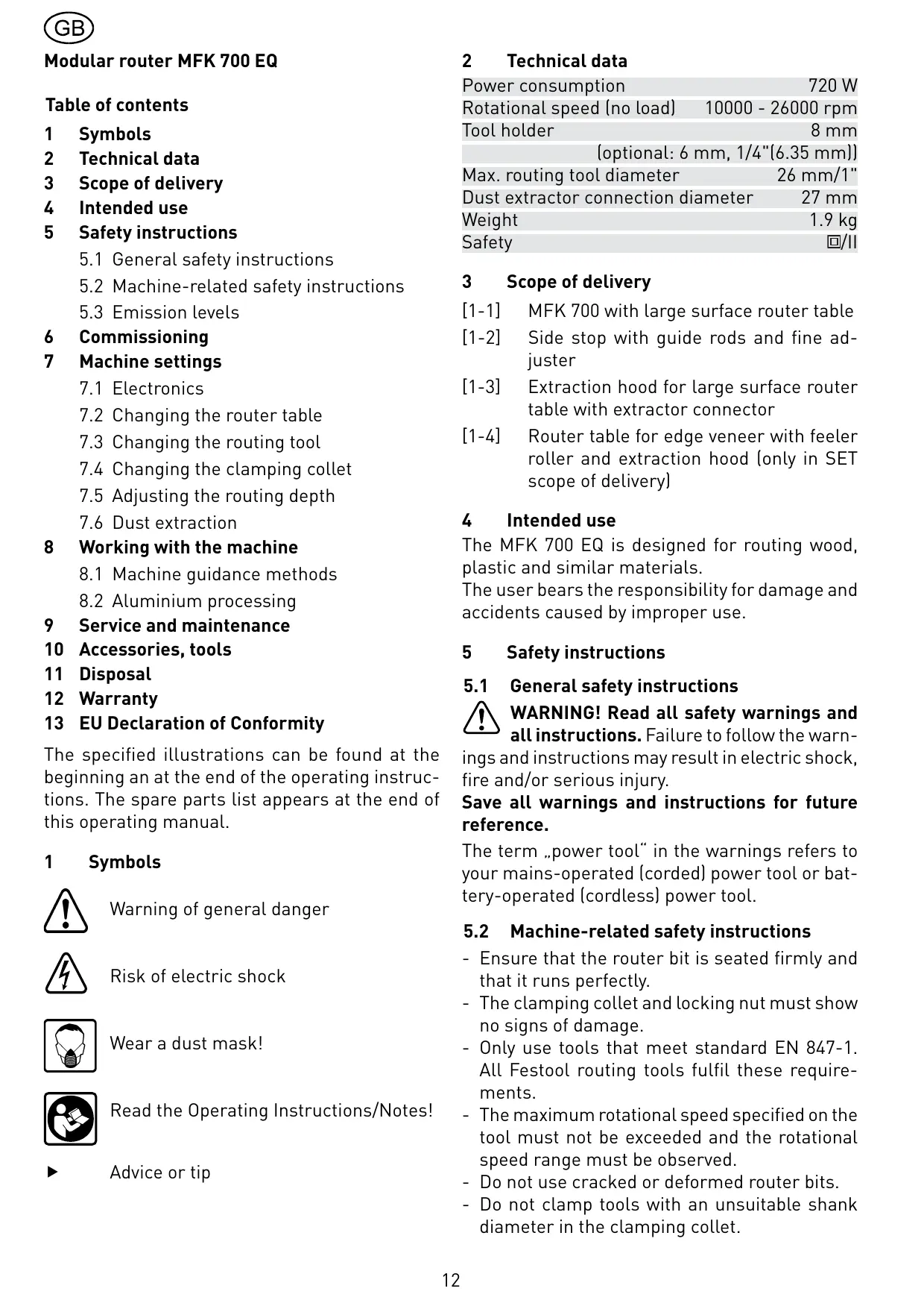
1 Symbols

Warning of general danger

Risk of electric shock

Wear a dust mask!

Read the Operating Instructions/Notes!

Advice or tip
2 Technical data
Power consumption 720 W
Rotational speed (no load) 10000 - 26000 rpm
Tool holder 8 mm
(optional: 6 mm, 1/4" (6.35 mm))
Max. routing tool diameter 26 mm/1"
Dust extractor connection diameter 27 mm
Weight 1.9 kg
Safety
3 Scope of delivery
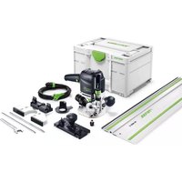
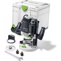
[1-1] MFK 700 with large surface router table
[1-2] Side stop with guide rods and fine adjuster
[1-3] Extraction hood for large surface router table with extractor connector
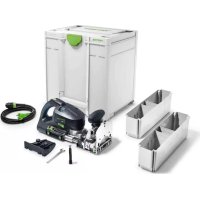
[1-4] Router table for edge veneer with feeler roller and extraction hood (only in SET scope of delivery)
4 Intended use
The MFK 700 EQ is designed for routing wood, plastic and similar materials.
The user bears the responsibility for damage and accidents caused by improper use.
5 Safety instructions
5.1 General safety instructions
WARNING! Read all safety warnings and all instructions. Failure to follow the warnings and instructions may result in electric shock, fire and/or serious injury.
Save all warnings and instructions for future reference.
The term „power tool“ in the warnings refers to your mains-operated (corded) power tool or battery-operated (cordless) power tool.
5.2 Machine-related safety instructions
- Ensure that the router bit is seated firmly and that it runs perfectly.
- The clamping collet and locking nut must show no signs of damage.
- Only use tools that meet standard EN 847-1. All Festool routing tools fulfil these requirements.
- The maximum rotational speed specified on the tool must not be exceeded and the rotational speed range must be observed.
- Do not use cracked or deformed router bits.
-
Do not clamp tools with an unsuitable shank diameter in the clamping collet.
-
Only guide the electric power tool along the workpiece when switched on.
- Keep your hands away from the routing area and the router bit. Hold the additional hand grip or the motor housing with your other hand.
- Never rout through metal objects, nails or screws.
- Secure the workpiece.
- Take appropriate protective measures when performing work that may generate harmful, combustible or explosive dust. Never process material containing asbestos.
- Wait until the machine has stopped before setting it down.
- Wear suitable protection such as ear protection, safety goggles, a dust mask for work which generates dust, and protective gloves when working with raw materials and when changing tools.
5.3 Emission levels
Noise levels are measured in accordance with EN 60745:
Sound pressure level LPA = 78 dB(A)
Noise level LWA = 89 dB(A)
Uncertainty K = 3dB


CAUTION
The noise produced during work can damage your hearing.
Always use ear protection!
Overall vibration levels (vector sum for three directions) measured in accordance with EN 60745:
Vibration emission level (3-axis) a_b = 3,0 ~m / s^2
Uncertainty K = 2,0m / s^2
The emission values specified (vibration, noise) were measured in accordance with the test conditions stipulated in EN 60745 and are intended for machine comparisons. They are also used for making preliminary estimates regarding vibration and noise loads during operation.
The emission values specified refer to the main applications for which the power tool is used. If the electric power tool is used for other applications, with other tools or is not maintained sufficiently prior to operation, however, the vibration and noise load may be higher when the tool is used. Take into account any machine idling times and downtimes to estimate these values more accurately for a specified time period. This may significantly reduce the load during the machine operating period.
6 Commissioning


WARNING
Risk of accident if the machine is operated using unauthorized voltages or frequencies.
- The mains voltage and the frequency of the power source must correspond with the specifications on the machine's name plate.
- In North America, only Festool machines with voltage specifications of 120 ~V may be used.
The switch [2-2] is an on/off switch (1 = ON, 0 = OFF). Connecting and detaching the mains power cable, see Fig. [3].
7 Machine settings


WARNING
Risk of accident, electric shock
- Always pull the plug out of the socket before performing any type of work on the machine.
7.1 Electronics
The machine features full-wave electronics with the following properties:
Smooth start-up
The electronically controlled smooth start-up function ensures that the machine starts up smoothly.
Speed control
You can regulate the rotational speed steplessly between 10000 and 26000 rpm using the adjusting wheel [2- 1]. This enables you to optimise the cutting speed to suit the respective material.
Constant speed
The preselected motor speed remains constant through electronic control. This ensures a uniform cutting speed even when under strain.
Temperature control
To prevent overheating, the safety electronics switches the machine off when it reaches a critical motor temperature. Let the machine cool down for approx. 3-5 minutes before using it again. The machine requires less time to cool down if it is running, i.e. in neutral position.
7.2 Changing the router table
The large surface router table is already fitted as standard. The large contact surface and precision
adjustment features of this router table enable a high degree of accuracy. Other router tables are included in the accessories programme.
a) Large surface router table
- Slide the router table onto the retaining pin on the machine.
- Tighten the screw [4-1] to clamp the router table in position.
- Place the extraction hood [4-2] in position.
- Tighten the screw [4-3] to clamp the extraction hood in position.
- Place the extractor connector [4-4] on the extraction hood.
Removal is performed in reverse sequence to installation.
b) Router table for edge veneer
The "router table for edge veneer" (only in SET scope of delivery) is designed for flush trimming veneer overhang and profile routing.
- The router table is tilted 1.5^ so that the surface coating is not damaged during edge routing. A router table with 0^ inclination angle for precise cuts is available as an accessory.
- Secure the sensor [5-1] to the machine using the preassembled screws. Slide the sensor in the long holes to adjust the routing tool to the perfect position.
- Slide the router table onto the retaining pin on the machine.
- Tighten the screw [5-2] to clamp the router table in position.
- Place the extraction hood [5-3] in position.
- Tighten the screw [5-4] to clamp the extraction hood in position.
Removal is performed in reverse sequence to installation.
7.3 Changing the routing tool


WARNING
Risk of accident - the routing tool may be hot after use and has sharp edges.
- Allow the tool to cool before changing.
-
Wear protective gloves when changing tools.
-
Remove the router table before changing the routing tool.
a) Removing the tool
- Press the spindle lock [6-1].
- Unscrew the locking nut [6-2] using the open-end wrench (size 19) until you are able to remove
the tool.
- Release the spindle lock [6-1].
b) Inserting the tool
- Insert the routing tool [6-3] into the open clamping collet as far as possible, but at least up to the mark () on the shank.
- Press the spindle lock [6-1].
- Tighten the locking nut [6-2] using the open-end wrench (size 19).
- Release the spindle lock [6-1].
7.4 Changing the clamping collet
Only compatible tools can be used in combination with the clamping collets supplied. 8mm , 6mm and 1/4'' (6.35 mm) clamping collets can be used.
- Press the spindle lock [7-1].
- Unscrew the locking nut [7-2] completely.
- Release the spindle lock [7-1].
- Remove the locking nut from the spindle together with the clamping collet [7-3]. Do not separate the locking nut and clamping collet as these form a single component.
- Attach a different clamping collet with locking nut to the spindle.
- Screw on the locking nut loosely. Do not tighten the locking nut until a router bit is inserted.
7.5 Adjusting the routing depth
- Unscrew the rotary knob [8-3] and the clamp [8-1] (large surface router table only).
- Turn the rotary wheel [8-2] to set the router table to the required routing depth.
- Tighten the rotary knob [8-3] and the clamp [8-1] (large surface router table only).
7.6 Dust extraction


CAUTION
Dust may be harmful or cause allergic reactions!
- Always connect the machine to a dust extractor.
- When performing work that generates dust, always wear a dust mask.
Extraction hoods are supplied for both router tables; a Festool extractor (extractor hose with a diameter of 27 ~mm ) can be connected to these extraction hoods.
The dust extractor (extractor hose with dia. 27mm ) can also be attached to the large surface router table or the side stop depending on the application.

WARNING
Risk of injury
- Hold the machine with both hands.
- Always secure the workpiece in such a manner that it cannot move while being routed.
Guide the machine along the workpiece at a steady rate of advance.
8.1 Machine guidance methods
a) Routing with side stop
The side stop is positioned parallel to the workpiece edge.
The side stop can only be fitted to the large surface router table without a fitted extraction hood [4-2].
- Insert the fine adjuster [9-3] into the side stop.
- Secure both guide rods [9-5] with the two rotary knobs [9-2] on the side stop.
- Insert the side stop into the grooves on the router table to the required distance and secure the guide rods by turning the rotary knob [9-1].
Rough adjustment
- Loosen the screws [9-2] and [9-4] and slide the side stop.
- Tighten the screws.
Fine adjustment
- Loosen the screws [9-2] and turn the green wheel on the fine adjuster [9-3].
The distance between each line on the rotary wheel is 0.1 ~mm - one full turn of the ring represents 1 ~mm . - Tighten the screws [9-2].
b) Edge trimming with bearing guide [Fig. 10]
Use routing tools with a bearing guide in the machine when edge trimming with the large surface router table. The machine is then guided in such a way that the bearing guide rolls off the workpiece.
When trimming edges, always use the extraction hood [10-1] for improved dust extraction.
c) Edge trimming with sensor and router table for edge veneer [Fig. 11]
When edge trimming with the router table for edge veneer (only in SET scope of delivery), fit the sensor [11- 1] to the machine (see Chapter 7.2 b).
The machine is then guided in such a way that the sensor rests against the workpiece.
8.2 Aluminium processing

WARNING
Risk of accident - always perform the following safety measures when routing aluminium:
- Add a residual-current circuit-breaker (FI, PRCD).
- Connect the machine to a suitable dust extractor.
- Remove dust deposits from the motor housing on a regular basis.
- Wear protective goggles.
9 Service and maintenance


WARNING
Risk of accident, electric shock
- Always pull the plug out of the socket before performing any type of work on the machine.
- All maintenance and repair work which requires the motor housing to be opened must only be carried out by an authorised service workshop.
- Check the plug and the cable regularly and should either become damaged, have them replaced by an authorised after-sales service workshop.
- To ensure constant air circulation, always keep the air vent slits in the motor housing clean and free of blockages.
The machine is equipped with self-disconnecting special carbon brushes. If they are worn, power is interrupted automatically and the machine comes to a standstill.
10 Accessories, tools
Use only original Festool accessories and Festool consumable material intended for this machine because these components are designed specifically for the machine. Using accessories and consumable material from other suppliers will most likely affect the quality of your working results and limit any warranty claims. Machine wear or your own personal workload may increase depending on the application. Protect yourself and your machine, and preserve your warranty claims by always using original Festool accessories and Festool consumable material!
The order numbers of the accessories and tools can be found in the Festool catalogue or on the Internet under "www.festool.com".
11 Disposal
Do not throw the power tool in your household waste! Dispose of machines, accessories and packaging at an environmentally-responsible recycling centre. Observe the valid national regulations.
EU only: European Directive 2002/96/EC stipulate that used electric power tools must be collected separately and disposed of at an environmentally responsible recycling centre.
12 Warranty
For our tools, we give warranty for material and production defects in accordance with the locally applicable legal provisions, but in any case for at least 12 months. Within the EU member states, the warranty period is 24 months (verification through invoice or delivery note). Damage caused by, in particular, natural wear, overloading, incorrect handling, or damage caused by the operator, or damage caused through use of the equipment contrary that specified in the operating manual, or damage which was known at the time of purchase, is not covered by the warranty. Furthermore, damage caused by the use of non-original accessories and consumable materials (e.g. sanding pads) is also excluded.
Complaints can only be recognised if the tool is returned while still assembled to the supplier or an authorised Festool Customer Service workshop. Keep the operating manual, safety instructions, spare parts list and purchase receipt in a safe place. Otherwise the respective, current warranty conditions of the manufacturer shall apply.
Note
Due to continuous research and development work, we reserve the right to make changes to the technical content of this documentation.
13 EU Declaration of Conformity
| Modular router | Serial no. |
| MFK 700 EQ | 494964, 494973 |
| Year of CE mark: 2007 | |
We declare at our sole responsibility that this product is in conformity with the following standards or standardised documents: EN 60745-1, EN 60745-2-17, EN 55014-1, EN 55014-2, EN 61000-3-2, EN 61000-3-3 in accordance with the regulations 2006/42/EC, 2004/108/EC.
paa. 0j. Jdaannn nn
Dr. Johannes Steimel 11.01.2010
Head of Research, Development and Technical Documentation

Festool GmbH
Wertstrasse 20
73240 Wendlingen, Germany
REACH for Festool products, their accessories and consumables
REACH is a European Chemical Directive that came into effect in 2007. As “downstream users” and product manufacturers, we are aware of our duty to provide our customers with information. We have set up the following website to keep you updated with all the latest news and provide you with information on all the materials used in our existing products: www.festool.com/reach
Fraise modulaire MFK 700 EQ
Sommaire
10 Accessoires, outfits
Varning for allman risk!

Risk for elastot

8.2 Aluminiumbearbeting

WARNING!
UpoBHeH 3BykoBOro daBLeHnRA LPA = 78 dB(A)
UpoBHeb MoUHOCTN 3ByKOBoBIX KOJe6aHnI