XL DF 700 - Milling machine FESTOOL - Free user manual and instructions
Find the device manual for free XL DF 700 FESTOOL in PDF.
User questions about XL DF 700 FESTOOL
0 question about this device. Answer the ones you know or ask your own.
Ask a new question about this device
Download the instructions for your Milling machine in PDF format for free! Find your manual XL DF 700 - FESTOOL and take your electronic device back in hand. On this page are published all the documents necessary for the use of your device. XL DF 700 by FESTOOL.
USER MANUAL XL DF 700 FESTOOL
Original operating manual
1 Symbols 12
2 Technical data 12
3 Machine features. 12
4 Intended use 12
5 Safety instructions 12
6 Operation 13
7 Settings 13
8 Working with the machine 15
9 Service and maintenance. 16
10 Troubleshooting 16
11 Accessories 17
12 Environment. 17
The illustrations specified are located at the beginning and end of the operating manual.
1 S y m b 0

Warning of general danger

Risk of electric shock

Read the Operating Instructions/Notes!

Wear ear protection.

Wear a dust mask.

Wear protective gloves.

Disconnect from the power supply!

Burning risks from hot surfaces!

Do not throw in the household waste.
2 T e c h n
Joiner DF 700 EQ
| Power | 720 W |
| Speed (no load) n0 | 21000 rpm |
| Routing depth | 15 - 70 mm |
| Routing width, max. | 16,5 mm + ∅ cutter |
| ∅ cutter, max. | 14 mm |
Joiner DF 700 EQ
| Connecting thread of the drive shaft | M8 x 1 |
| Weight (excluding cable) | 5,2 kg |
| Safety class | ☐ /II |
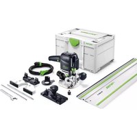
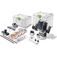
3 Machine features
[1-1] Rubber buffer
[1-2] Stop pins
[1-3] Handles
[1-4] On/Off switch
[1-5] Display for dowel hole width
[1-6] Adjusting lever for dowel hole width
[1-7] Slide for routing depth adjustment
[1-8] Snap button for routing depth adjustment
[1-9] Marker for routing depth adjustment
[1-10] Unlocking of motor unit/guide frame
[1-11] Selection slide for routing height adjustment
[1-12] Clamp lever for routing angle adjustment
[1-13] Button for releasing stop pins
[1-14] Clamp lever for routing height adjustment
[1-15] Extractor connector
[1-16] Spindle lock
[1-17] Mains power cable
4 Intended use
The machine is intended to create DOMINO dowel connections in hard and soft wood, chipboard, plywood and fibreboard. All applications beyond this are regarded as unintended use.
The machine is designed and approved for use by trained persons or specialists only.

The user is liable for improper or non-intended use.
5 Safety instructions
5.1 General safety instructions
WARNING! Read all safety warnings and all instructions. Failure to follow the warnings and instructions may result in electric shock, fire and/or serious injury.
Save all warnings and instructions for future reference.
The term "power tool" in the warnings refers to your mains-operated (corded) power tool or battery-operated (cordless) power tool.
5.2 Machine-related safety instructions
- Hold power tool by insulated gripping surfaces, because the cutter may contact its own cord. Cutting a "live" wire may make exposed metal parts of the power tool "live" and could give the operator an electric shock.
- The tools must be rated for at least the speed marked on the power tool. Tools running over rated speed can fly apart and cause injury.
- Use the machine only with the guide frame mounted. The guide frame protects the user against broken-off parts of the jointer bit and accidental contact with the jointer bit.
- Only cutters provided by Festool for this purpose may be mounted on the power tool. The use of other cutters is prohibited due to the increased risk of injury.
- Never use dull or damaged mortising bits. Dull or damaged mortising bits can cause the tool to lurch sideways unexpectedly and lead to a loss of control of the power tool.
- Do not resharpen cutters more than twice. Resharpened cutters may affect the precision of the cutting results.
- Do not operate the tool if the spring-loaded fence does not return to its forward rest position. The fence covers the mortising bit and prevents accidental contact. If the slides of the fence do not move freely, have the tool serviced immediately.
5.3 Emission levels
Levels determined in accordance with EN 60745 are typically:
| Sound pressure level L | PA = 83 dB(A) |
| Noise level L | WA = 94 dB(A) |
| Measuring uncertainty allowance | K = 3 dB |

CAUTION
Operating noise
Damage to hearing
▶ Use ear protection!
Vibration emission value a_h (vector sum for three directions) and uncertainty K measured in accordance with EN 60745:
Handle a h < 2,5m / s^2 Uncertainty K = 1,5m / s
The specified emissions values (vibration, noise)
- are used to compare machines.
- They are also used for making preliminary estimates regarding vibration and noise loads during operation.
- They represent the primary applications of the power tool.
Increase possible for other applications, with other insertion tools or if not maintained adequately. Take note of idling and downtimes of machine!
6 0 p e r a t

WARNING
Unauthorised voltage or frequency!
Risk of accident
The mains voltage and the frequency of the power source must correspond with the specifications on the machine's name plate.
In North America, only Festool machines with the voltage specifications 120V / 60Hz may be used.

Always switch the machine off before connecting or disconnecting the mains power cable!
Connecting and detaching the mains power cable [1-17] see Fig. [2].
The switch [1-4] is an on/off switch 1 = ON, 0 = OFF .
Peel off the protective film from the bottom of the guide frame [3-4].
Remove the transport safety device [1-18].
7 Settings

WARNING
Risk of injury, electric shock
Always pull the mains plug out of the socket before performing any type of maintenance on the machine!
7.1 Electronics
The machine features full-wave phase control electronics with the following features:
Smooth start-up
The electronically controlled smooth start-up ensures that the machine starts up jolt-free.
Constant speed
The motor speed remains constant through electronic control to ensure a uniform cutting speed even
when under load.
Temperature cut-out
The machine power supply is limited and the speed reduced if the motor exceeds a certain temperature. The machine continues operating at reduced power to allow the ventilator to cool the motor quickly. If the machine temperature exceeds the maximum permitted value for longer periods, the machine switches off completely after approx. 40 seconds and can only be switched on again once the motor has cooled sufficiently.
Restart protection
The integral restart protection prevents the machine from automatically starting up again after an interruption in power when the machine is used in continuous operating mode. In this case the machine must be switched off and then switched back on again.
7.2 Changing tools

CAUTION
Hot and sharp tools
Risk of injury
Do not use insert tools that are blunt or defective.
Wear protective gloves.
Removing the tool
- Lift the unlocking device [3-2] until it audiably disengages using the open-ended spanner [3-3] supplied (SW 12).
Separate the motor unit [3-5] from the guide frame [3-4].
Press and hold the spindle lock [4-1]. - Loosen the cutter [4-3] using the open-ended spanner [4-2] and remove.
Release the spindle lock [4-1].
Inserting the tool

WARNING
Risk of injury
Before inserting a new cutter ensure that the machine, the guide frame and the guides [3-1] and [3-6] are clean.
Remove any contamination that may be present.
Only use sharp, undamaged and clean tools.
Press and hold the spindle lock [4-1].
Use the open-ended spanner [4-2] to screw on the cutter [4-3].
Release the spindle lock [4-1].
▶ Slide the guide frame [3-4] onto the motor unit [3-5] until it audibly engages.
7.3 Setting the Mortise Depth

WARNING
Cutter can come out at the rear side of the workpiece.
Risk of injury
- Set the routing depth at least 5mm less than the workpiece thickness.
Press one or two snap buttons [1-8].
Set the slide for the routing depth setting [1-7] to the desired routing depth (15 - 70 mm).
Release the snap buttons [1-8].
Check whether the slide [1-7] has engaged correctly.
① With the two markers [1-9], you can mark two routing depths and switch easily between them using the slide 1-7.
7.4 Setting the Fence Height
① The alignment of the clamp levers [1-12] and [1-14] can be aligned by raising the levers. When tightened, the levers should not protrude beyond the contact surface.
a) with selection slide
- Loosen the clamp lever for the routing height adjustment [5-1].
Using the front handle [5-2] raise the front part of the guide frame.
Use the selection switch to set [5-6]the desired routing height h (10 mm; 15 mm; 20 mm; 25 mm; 30 mm; 40 mm).
Press the front section of the guide frame downwards as far as the stop.
Close the clamp lever [5-1].
b) freely selectable
-
Loosen the clamp lever for the routing height adjustment [5-1].
Using the front handle [5-2] raise the front section of the guide frame.
Pull the selection slide [5-6] as far as the stop in the direction of the motor unit. -
Set the desired routing height h using the scale [5-3] by moving the front section of the guide frame vertically.
Close the clamp lever[5-1].
7.5 Setting the Fence Angle
- Loosen the clamp lever for the angle adjustment [5-4].
Set the desired angle:
using the scale [5-5] variable from 0^ to 90^ .
locking at 0^ ; 22.5^ ; 45^ ; 67.5^ ; 90^ .
Close the clamp lever [5-4].

Set the routing height and depth as low as possible when metre routing as otherwise there is a risk that the cutter will come out the other side.
7.6 Setting the Mortise Width
Use the adjusting lever [1-6] to adjust the width of the dowel hole you intend to cut for an adequate fit or set with 3mm play:
Tight fitting dowel 13.5mm+ cutter diameter
Dowel with lateral 16.5mm+ cutter diameter play
You can see on the display [1-5] what dowel hole width is selected.
7.7 Setting stop pins
Six stop pins [1-2] are available on the stop side of the DOMINO joining machine.
Stop pins that are not required can be individually engaged by exerting overpressure and released using the button [1-13].
These serve as spacers to the cutter centre and can be inserted at different locations - see image [6]:
A Three possible spacings to a supply side [1 - 2 - 3]
B Two dowel holes beside each other from a supply side (1 - 3)
C Two dowel holes by changing the workpiece, e.g. for cross-section cut.
7.8 Dust extraction

WARNING
Dust hazard
Dust can be hazardous to health. Always work with a dust extractor.
Always read applicable national regulations before extracting hazardous dust.
At the extractor connector [1-15], a Festool mobile dust extractor with an extraction hose diameter of 27mm can be connected.
7.9 Widening the contact surface
The contact surface widening device [7-1] can be used to enlarge the contact surface when routing on the workpiece edge, thus allowing safer guidance of the machine.
- Secure the contact surface widening device using the two screws [7-2] on the threaded holes [7-3] of the guide frame.
The contact surfaces of the contact surface widening device [7-5] and the table [7-4] must be level.
8 Working with the machine
Wood is a natural, non-homogenous material and because of this, its dimensions will most likely deviate slightly during processing, even if the machine is set accurately. Machine handling also influence the degree of working accuracy (e.g. fast-feed speed). Furthermore, the dimensions of wooden DOMINOs may vary (for example, due to humidity), regardless of how they are stored. All of these factors influence the dimensional accuracy of manufactured dowel holes and dowelling joints.
① We recommend routing and joining a test workpiece before machining the actual workpiece.

Please observe all mentioned safety informations and the following rules when working:
- Always secure the workpiece in such a manner that it cannot move while being processed.
- Always hold the machine with two hands on the handles [1-3] when performing work. This reduces the risk of injury and is a prerequisite for precise work.
- Close the clamp lever for routing height adjustment [1-14] and the clamp lever for angle adjustment [1-12] to avoid unintentional loosening during operation.
- Adapt the feed rate to the cutter diameter and material. Work with a constant feed rate
- Only lay the machine aside when the cutter has come to a complete standstill.
- Always connect the machine to a dust extractor.

For work that generates dust, wear a dust mask.
Procedure
Proceed as follows to create a DOMINO dowelling joint:
See chapter
- Select a DOMINO dowel and insert the suitable bit into the DOMINO joining machine. 7.2
- Set the routing depth. 7.3
- Set the routing height. 7.4
- Adjust the routing angle if necessary. 7.5
- Mark the areas on the workpieces that belong together [8-1] so that you will be able to join them correctly again once you have cut the dowel holes.
- APosition the two workpieces to be joined against one another and mark the desired positions of the DOMINO dowels with a pencil [8-2].
- Select the required stop pins. 7.7 B
- Set the desired dowel hole width (adequate fit or with 3mm play). 7.6
-
Cutting the dowel holes [8]:
-
The first dowel hole by attaching the stop pin to the side edge of the workpiece.
- The following dowel holes according to the previously made pencil markings and the scale of the vision panel [8-3].
Our recommendation: Please check each dowel hole for chippings and clear these if necessary.
Always work with a dust extractor to improve the removal of chippings.
See chapter
Route the first hole for each workpiece without play (dowel hole width = DOM-INO dowel width) and the other dowel holes with the large dowel hole width.
9 Service and maintenance

WARNING
Risk of injury, electric shock
Always disconnect the mains plug from the socket before performing maintenance work on the machine!
All maintenance and repair work which requires the motor housing to be opened must only be carried out by an authorised service workshop.
The machine is equipped with special carbon brushes. If they are worn out, the power is interrupted automatically and the machine comes to a standstill.
Observe the following instructions:
To ensure constant air circulation, always keep the cooling air openings in the housing clean and free of blockages.
Clean the guides [3-1] and [3-6] of dust deposits.
Oil the guides regularly and lightly with resin-free oil (e.g. sewing machine oil).
We recommend an annual inspection and/or a check after approx. 100 operating hours at an authorised customer service workshop. This is for the safety of the user and the value stability of the power tool.
10 Troubleshooting
| Fault Cause Solution | ||
| Burns | Blunt cutter | Use sharp cutter |
| Dowel hole too narrow. DOMINO dowel cannot be jointed. | a. Blunt cutter b. Deposits (e.g. chippings in the dowel hole) | a. Use sharp cutter b. Remove deposit and work with dust extractor |
| Widening of the dowel hole with 8 mm cutter | Routing depth too large (larger than 50 mm) | Reduce routing depth (max.50 mm) |
| Splinters at edge of dowel hole | Excessive feed rate | Reduce feed rate |
| Dowel hole not parallel to work- piece edge | Workpiece has shifted during processing | Secure workpiece properly |
| Tool cannot be loosened during tool change | Spindle lock not functioning Twist | spindle against the tool using an open-ended spanner. If this occurs several times contact the after-sales service department. |
| The positions of the dowel holes which are created with one of the left and one of the right stop pins do not match precisely. | The stop pins are selected different on the right and left. | Select the same stop pins on the left and the right. |
| DOMINO joining machine operates irregularly, jerks | a. No dust extractor connected b. Rubber buffer [1-1] worn | a. Connect dust extractor b. Replace rubber buffer (sparse part) |
11 Accessories
The order numbers of the accessories and tools can be found in the Festool catalogue or on the Internet under "www.festool.com".
Festool provides comprehensive accessories which allow you to use your machine effectively and for diverse applications, e.g.:
Handrail fence RA-DF 500/700
Cross stop QA-DF 500/700
- Stopper LA-DF 500/700
Assembly instructions are included at the end of the operating manual.
12 Environment
Do not dispose of electric power tools in household waste! Recycle devices, accessories and packaging. Observe applicable country-specific regulations.
EU only: In accordance with European Directive on waste electrical and electronic equipment and implementation in national law, used electric power tools must be collected separately and handed in for environmentally friendly recycling.
Information on REACH: www.festool.com/reach
Deuvelfreez DF 700 EQ
| Vermogen | 720 W |
| Toerental (onbelast toerental) n0 | 21000 min-1 |
| Freesdiepte | 15 - 70 mm |
| Freesbreedte, max. | 16,5 mm + Φ-frees |
Varning for allman risk!

Varning for elstotar

$$ w _ {A} = 9 4 d B (A) $$
Osakerhet K = 3 dB

OBSERVER
$$ w _ {A} = 9 4 d B (A) $$
7.4 Stille inn fresehoyde
7.5 Stille inn fresevinkel
Løsne hendelen for vinkelinnstilling [5-4].
Still inn onsket vinkel:
ut fra skalaen [5-5] trinnlost fra 0^ til 90^
gär i las ved 0^ . 22,5^ . 45^ . 67,5^ . 90^
Lås hendelen [5-4].

5 Yka3aHnNo TExHnKe 6e3oNaChOCTn
5.1 06uhe yka3aHnno TExnKe 6e3oNaChOCTn

PpeynpeKdHne! PpOHTte BcyeKa3aHnno Texnke 6e3oNaChocTn n HcTpyKu.
HeToUHoe c6JIoDeHne HnCTpyKcN IN npEynpeXeHN MoKeT CtaTB npuHNoYdapa 3JekTpueckm TOKOM, Noxapa N/INn TjXeJIbIX TpaBM.
CoxpaHЯITe Bce yKa3aHnNo TeXHnKe 6e3oNaChocTn n HnCtpyKcnn.
IcnoJb3yEmbI B yka3aHnX NO TEXHKe 6e3oNaChocTn TepMH «3JeKtpOnHCTpyMeHT> OTHOCITcK cTeBbIM 3JeKtpOnHCTpyMeHTam (C ceTeBbIM Ka6eJIem) N aKKMyJrTOpHbIM 3JeKtpOnHCTpyMeHTam (6e3 cTeBOrO ka6eJIa).
5.2 Yka3aHnno TeXnke 6e3oNaChocTn npnNoIb30BaHHn HhCTpyMeHTOM
-ДерхиTe элкгоннсрунгToько 3a
ИЗолюванны руков,Tak KaK Фpe3a
Может NOВpeДNTb ceTeBOH Ka6eЛь
ИНструмента.KoHTaKT c NOВрждэнБIM
элкгшчecКи Мабелм чepe3 HaxODЯшеся
ПОД HANРЯЖЕпМ MeTALINЧECKNe YactN
ИНструмента Может ПprIBeCTn K ydapy
элкгшчecКи TOKOM.
-При ИСпОЛьЗОВAHМИНСТРУМЕТА Heo6xOДМо yuHTbIbA Tb yKa3aHHyU Ha 3JIeKТponHCTPуMeHTе qactoty BpaueHnBala. HcTpyMeHT, npeBbIshaIOUne BO BpemЯ pa60TbI HOMHaJIbHoe YncNo O6OpOTOB, MOrYt pa3JIeTaTbCЯ Ha qactN, HahOcЯ Пprn 3TOM TpaBMbl.
-ИспобьунTe MaшинКу TОльбк O C
ПОДСоЕДNH�нБIM HANpaBЯюцIM
6лokOM.HanpaВяюци 6лOK 3aшицаET
Nolb3oBaTeJr OT OTNoMaHHbIX YacTeHnCTpyMeHTa NOTcIyauHOrO KacaHnA fpe3bl.
- YctaHaBnBaIte Ha MaunHKy TOnbKO fpe3bl, npedlaraeble Festool. PpIMHeHne Dpyrnx fpe3 13-3a IOBbIeHHoTpaBMooNacHOCTN 3anpeueHo.
-3anpeaetcpa6ota c 3atynBwMnncn nn nobpejddHbIMn fpe3am. 3atynBwneecn nn nobpejdeHHbIe fpe3bl Moryt cTaTb npuHoi nOtepn KOHTpOJIa Hau dJleKTPoIHCTpyMeHTOM. - Φpe3bl MoKHO NepeTaunBaTb TOnbKO Dba pa3a. NpeTeoueHHbIe fpe3bl MOrYT OtpuataJIbHo NOBnraTb Ha pe3yJbTaTb fpe3epoBaHn.
-Прн OTnyckaHn6loka DBrHrTeJ6IOK BO3BpaaaetcB HcxOHyIO N03uNIO C NOMoUbIO npyXHHOro MexaHN3Ma, TaK YTO 0pe3a NOHocTbIO 3aKpbIBaETc4 3auNTHO KpbIshkoEcln 0pe3a He 3aKpbIBaETc4 KpbIshko, TOTuac BbIKluOHTe 3JIeKtpOnHCTpyMeHT n cdaIte erO B peMOHT.
5.3 YpOBNn Wyma
OnpeJeHbIe B COOTBeTCTBn c EN 60745 TINOBIE3HaueHnA:
YpoBHeHb 3ByKOBOrO LpA=83D(B(A)ДаВлелня
YpoBHeMb MoUHocTn 3ByKOBbIX LwA=94D(A) KOJIe6aHm
IorpeuHoctbK=3dE

OcTopoXHo
Uym, Bo3HkaOuπn npn pa6oTe
PobpekdeHne opraHOB clyxa
Pn pa6oTe nCnoB3yIe 3aunTHbIe HauHnKn!
Ko3ΦnueH Tmccnn Kone6aHn ah (cymma Bektopob Tpex HappaBHeHn) n porpeWoctb K paaccuTbBaIOTc corlaCHO EN 60745:
PykoTka a h<2,5 M/c²
IogpeuHoctb K=1,5M/c 2
Yka3aHHbIe 3HaueHnry ypoBnry Bn6paun
- cnykataIЯ copaBHeHnIHCTpyMeHTOB
MOXHO TaKKe NCNoJIb3OBaTb ДЯпразытельно OceHKn WymOBoN Bn6paunOHNo Harpy3KN Bo BpeMa pa6Otbl; - OTPaKaIOT OCHOBHeIe 0bJaCTn npUmHeHnnaJJIeKTPoINHcTpymEHTa.
Pn nCnoB3OBaHm MaunHKn B Dpyrnx ceJx, C dpyrmm CMeHHbIMn (pa6oumn) HNCTpyMeHTamn HnB Cnyae NX HeyDoBneTBOpntelbHorO 06cIyKmbAHn yMBoBa N Bu6paOnOHna Ha rpy3Kn MOrTy Bo3pactaTb. Co6IoudaTe 3NaueHn BpeMeHn pa6ToHa XoJocTOM XOdy N BpeMeHn nepepbIOB B pa6Ote!
6 Hauano pa60tbl
PpeDynpexKdEHNHe
Hedonycnmoe HanpajkeHne nn qactota!
OnachocTh Heecacthoro cnuya
CeteBoe HnprjKeHne n qactota nctouHnka ToKa 10JXHbI COOTBeTCTBOBaTb DaHHbIM, yKa3aHHbIM Ha 3aBOdCKoT a6JIuKHe.
B CeBepHoi AmePuke MoXHo NcNoJb30BaTb TOnbKO MaunHKn Festool c xapaKTepeNCTko nO HanpJxKeHnO 120 B/60 T.

Bcerda BbIKIOuAaTe py6aHOK nepei noDCoeHNHeHnEM n OTcoeHNHeHnem ceTeBOrKa6eIa!
IopcoeHHeHne nOTcoeHHeHne ceTeBOrO KaBeJra [1-17]cm.pnc.[2].
IpeeknouateIb [1-4] BblnoHnaeT 0yHKUIO BblKJIouateIa (I = B K I,0 = B b)
Ipeed nepBbIM nCnoJb30BaHneM ydaJInte 3aunTHyIO pJeHky C HxHHei CTOpOhbl HnpaBnaIooero 6loka [3-4].
ydaJInte TpaHcnpTnpoBOuHbI ΦHKcaTop [1- 18].
7 H a c T p
PpeDynpexKdEHeN
Onachoctb TpaBMnpoBaHn, yap Tokom
Ipeen Hauanom IIO6bix pa6oT Ha py6aHKe Bcerda BbIHMaIte BNkU y3 po3eTKn!
7.1 3NeKtpoHnKa
Maunnka NMeet 3JIeKtpoHHyU qactb co CneDyUOuMMN CBOICTBaM:
PnabHbI nyck
Плавнын руcke с олескPoHно peгунрВкои obecпeeuBaet haayano pa6oTbI MaunHKn 6e3 OTdauN.
NoctoHHa yactota BpaueHn
YacToTa BpaueHnna 3JeKtpoBnraTeJIa NpOdepXnBaetcnoCToAHHOI C nOMoUbIO 3JeKtpoHnKn. BlaOapr 3ToMy daxe npn Harpy3Ke o6ecneuBaETc HEn3MeHHaN cKOpocTb
fpe3epoBaHn.
3aunta ot neperpba
Pn CInuKOM CNbHOM HArpeBe INHCTpyMeHTa
NoDaTuKa N UacToTa BpaUeHnnoHnxAOTc.
NHCtpymENT npoDoJxaeT paOtaTb c noHnxEHHo
MOuHocTbIO DnI OecneueHn 6bICTporo
oxJaXDeHn Ype3 CnCTEmy BO3dyuHOro
oxJaXDeHn DBuRatEn. Pn npoDoJXntelbHoN
3KcnPyataun Ha oHe neperpeBa npimepHo
Yepe3 40 C MaunHka NoHocTbU BblKnUoyaeTc.
PiBtOpHoe BKlUoyHne Bo3MoXHO TOLbKO NocJe
oxJaXDeHn DBuRatEn.
3aunTa oT noBtOpHoro nycKa
BcTpoeHHa 3aunTa OT NOBtOpHOro nycKa npedeTbpaaaetcra ABToMaTuYeCKn nYCK nHCTpyMeHTA B HeNpepbIBHom pexKmpepa60TbI nocLe npepbBaHnnoDaun ToKa. B 3Tom clyuae nHCTpyMeHT Heo6xOIMo Chauana BbIKIOUHTb, a 3aTeM CHOBA BKIOUHTb.
7.2 CmeHa pa6oery HcTpyMeHtA


OcTopoXHo
TopaHn oCtpbI cMeHHbI nHcTpymeHT OnacNoctb TpaBMnpoBaHHa
He nCnoJb3yIe 3aTyIINBwIeScn DeΦeKTHbIe CMeHHbIe NHCTpyMeHTbl!
HaedeBaIte 3aunTHbIe nepaTKn!
N3BJeueHne pa6oOero nHcTpymeHTa
PpHNOHmMte 6IoknpaTOp [3-2]do IeJyKa c NOMOuBIO pPnlaeremo raeHoro KJIoua (SW 12) [3-3].
Pa3beHnHTe 6loK DvraTeIa [3-5] n HaprabJIouIeN 6loK [3-4].
Haxmte u yepkBaIte cToOp 1nHdJIa [4- 1].
OToCoeHnTeΦpe3y[4-3]cIIOMoUbIOraeHOro KJIoua[4-2]N BbIHbTe N3rHe3da.
OTnyctnte cTOnOp wHnHdJIa [4-1].
YctaHOBka pa6oery nHcTpymeHa

PpeDynpexKdEHNHe
Onachoctb TpaBMnpoBaHn
Ipepe yctaHOBkoHOBoI pOBepbTe, OuHbI Jn MaunHka, HapBaJIooJn 6Jok n HapBaJIooJne [3-1].
YdaIte BO3MOKHbIe 3aIpa3HeHHa.
IoiB3yIeTcB TOJIbKO OCTpbIM N YNCTbIM HNCTpyMeHTOM 6e3 IOBpeJdeHn.
Haxmte n ydepknBaTe cToOp 1nHdJIa [4- 1].
C NOMOUIIraeHoro KJIIOa [4-2] 3aKpeNITe pe3y [4-3].
OTnyctnte cTOnOp wHnHdJIa [4-1].
HaBnHbTe HnpaBnaHm 6loK [3-4] Ha 6loK DnIraTeJ [3-5] Do uenuKa.
7.3 PerynpoBka rny6nHbI φpe3epoBaHn

PpeDynpexKdene
Φpe3a MoKet npoTn 3aRoTOBky HAcKB03b.
OnachocTh TpaBMnpoBaHn
YcTaHaBnBaIte rIy6nHy fpe3epoBaHna KaK MInHMym Ha 5 MM MeHbWe yem TOniHa 3aRoTOBKn.
Haxmnte oHy nIи o6e KhoNkn [1-8].
Otperynpyte noJ3yHKOM [1-7] HxKHyTO rny6nHy φpe3epoBaHnA (15-70 MM).
OTnyctnte KhoNkn [1-8].
PpOBepe, 3aΦnKcnpoBaIcra IIN nON3yHOK [1-7].
① C NOMOJIbIO MeTOK [1-9] MoXHO OTMeNTb IBe rIy6HbI φpe3epoBaHnI nPocTo nepeDBrTaTb MExkDy HmN IOn3yHOK [1-7] (HaNPmEp npn accmEtpruHOM paCNoJoxeHnBCTaBHbIX WInOB DOMINO pa3HoJ dINHbI).
7.4 PerynpoBka pa6oey BbICOTbl 0pe3bl
① 3axmHbIe pbIaI [1-12] [1-14]
pectablaIOTc nyTEm npnOHaMaHna. B 3aTAYTom COCToAHN OH He DoJXHbI BblCTyNaTb HaOnOpHO NoBepxHoCTbIO.
a) c nomoou noJ3yHka
Ocna6bTe 3axmHOn pbUar peylnpoBkn pa6oey BbICOTbI fpe3bl [5-1].
Пиюнмпe nepeHIOU qaCTb HanpaBЯHоцero 6LoKa 3a nepeHIOU pyuKy [5- 2].
C noMoUbI IO NOJ3yHka [5-6] yCTaHOBnte HxKHyO pa60uyIO BlicOTy fpe3bl (10 MM; 15 MM; 20 MM; 25 MM; 30 MM; 40 MM).
Haxmnte nepeHIOU qacTb HnpaBnaIooero 6loka do ynpa Bn3.
3aФИКСИРУТe рБИАг [5-1].
b)Ha BbI6op
Ocna6bTe 3axmHOn pbIar peRyInpOBKn pa60eB BICOTbI fpe3bl [5-1].
PpHNoDnMnTe nepeHIOU qAcTb HappaBJIHOeO 6Ioka 3a nepeHIOU pyky [5- 2].
CdBnhte nol3yHok [5-6] do ynpa B HappaBneHn 6Ioka DBrTaTeJ.
YCTaHOBnTe Heo6xOdmyo pa6oyu BbICOTy 0pe3bl no shkane [5-3], nepemeua nepeHIOU qactb HappaBIAIOe O 6loka B BePTKakbHom HAppaBHeHH.
3aФИКСИРУТe рbluаr [5-1].
7.5 Perynipobka yrna φpe3epoBaHn
Ocna6bTe 3aXmHOn pbIur perylnpoBkn yrna [5-4].
YCTaHOBnte HxHbIyroJ:
c nOmoIbU IkaJIbI [5-5] 6e3 fNkcaun OTO 0^ do 90^
cΦnKcaunéHα0°;22.5°;45°;67.5°;90°.
3aΦnKcnpyTe pbyar [5-4].
IpnΦpe3epoBaHnBycYctHaBnBaNte no BO3MOxHOCTn He60JbWyO pa6Ouyo BlicOTy Φpe3bl n rny6uHyΦpe3epoBaHn, nHaue Φpe3a MoKet npoTn 3aTOBky HAcKB03b. OnacHOCTb TpaBMnpoBaHn!
7.6 Perylnpobka shpnhb rHe3da noB BCTaBHOn
C nOmoBbIO pbIyara [1-6] MoXHO yCTaHOBnTb ⅢnpHry rHe3da 6e3 3a30pa nll c 3a30pOM 3 MM:
BCTaBHOI 6e3 13,5 MM+DnaMeTpΦpe3b3a30pa
BCTaBHOJ uHn c 16,5 MM+JaMaTeTp fpe3b60KOBbIM 3a3OpOM
BbIbpaHnyu u npHy rHe3da MoXHo nocMoTpeTb no HndnKaTopy [1-5].
7.7 PerynpobKa ynopHbIX BTyIok
Ha onopno CTOpOHe na3oBO-IO6eIbHoro 0pe3epa NMeetcra WeecTb ynpHbIX BtUJOK [1-2].
HeuCnoJb3yeMbIe ynpHbIe BTyIKN MoXHO NO OHN BKaTb Do ynpa NOCBO6OaNTb C NOMoUbIO KHOJIKN [1-13].
OHHcnykatay yctahOBKn paCCToHnA Do ceHTpa 0pe3epyeMoro OTBepCTnN MOryT NcNoJb3OBaTbcN no-pa3Homy (cm.pnc.[6]:
A TpN BO3MOxHbIX paCCToHnI Do OndHO Kpa[1-2-3]
B Dba rHe3da noD BCTaBHbIe Wnbl paDOM dpYc Dpyrom oT OndHoro Kpa8 (1-3)
C DBa rHe3da nOd BCTaBHbIe WnNbI NOBOpOTOM 3aRoTOBKn, HApPmEp PnI nonepueHOM pacnIe 06Bra3Kn.
7.8ПыileydaJIeHne

PpeDynpexKdEHe
OnapocTb 3dOpOBb B pe3yIbTaTe BO3deJCTBnIbn
MbIb MoKcET npeCTaBnTb ONaCHOctb IJr 3dopoBb. Po3tomy HnKoTa He pa6oTaTe 6e3 nbJIeydaJeHn.
Pn ydaJIeHnn onaCHOI JIa 3OpOBbI bJIIN Bcerda co6IouaIte HaUNHaJIbHbIe npedncaHna.
K naTpy6ky [1-15] moXHo NOdkHouHTb nbIleydaJiaHouu annapat Festool c dHaMeTpom BCacBbAioofo 7aHaRa 27 MM.
7.9 Pacunpntb onopbl
IcnoJb30BaHne paacnpuTeTne onOpbl [7-1] npn pe3epoBaHHn Ha KpOMKe 3aTOBKn N03BOJareyBeJIuHTb OOnPHyO NIOUaAdb N TEM CaMbIM NOBbICNTb HndEeXHOCTb pa60Tb C INHCTpyMeHToM.
3akpenTe pacwnpntelb onopbl DBymBnHTaMn [7-2], BBepyB nx B pe3b60BbieOTBepCTna [7-3] Ha HappaBraIooem 6Ioke.
OnopHbI NOBepxHOCTn pacwupnteTne ONOpbl [7-5] n OONOPHOH PNTbI [7-4] OJXHBt bITb ODHOBIOCKOCTN.
8 BbIopHeHne pa6oT c nOmoIbIO MaunHKn
Древесиа -эTO npnpoHbI HeODhopoHbIMatepnaI.ПOTOMy npi eO6pa60tke NocToaHNOJUaHTcO TKLOHeHn OTeaHaHOrO pa3Mepa,daXe KOrda pa6Ota BblOnHReTcT OTuHO HAcTpoEHbIM INCTpyMeHToM.Ha TOuHoCTb pe3yIbTaTAta BnIeT npeXmP a60tbl MaunHbI (HaNPmEp, cKOpocTb noaUn).Kpome TOrO MoXeMeHrTbcra pa3Mep DepeBAAHbIX uINOB DOMINO,ecn OHxpaHrTc,HaNPmEp BO BlaXHOMnomeueHN.Bce 3TN φakTopbl BnIaHOT Ha ToUHOCTbN3rTOBLeHHbIX rHe3d nOd BCTaBHbI uINbI ncamix WInIOBbIX coeINHeHn.
Declaration of Conformity
We as the manufacturer Festool GmbH, Wertstraße 20, 73240 Wendlingen, Germany declare under our sole responsibility that the product(s):
Designation:
Designation of Type(s):
Serial number(s) 1):
Joining machine
DF700EQ
499247
fulfills all the relevant provisions of the following UK Regulations:
S.I. 2008/1597 Supply of Machinery (Safety) Regulations 2008
S.I. 2016/1091 Electromagnetic Compatibility Regulations 2016
S.I. 2012/3032 Restriction of the Use of Certain Hazardous Substances in Electrical and Electronic Equipment Regulations 2012
and are manufactured in accordance with the following designated standards:
BS EN 60745-1:2009 +A11:2010
BSEN60745-2-19:2009+A1:2010
BSEN55014-1:2017
BSEN55014-2:2015
BSENIEC61000-3-2:2019
BSEN61000-3-3:2013
BS EN IEC 63000:2018
2) in the specified serial number range (S-Nr.) from 40000000-49999999

Place and date of declaration: Wendlingen, 03.05.2021
Signed on behalf of and in name of Festool GmbH
98

Markus Stark
Head of Product development
i. V. Q. G a molaf
Ralf Brandt
Head of Productconformity
de EU-Konformitätserklarung. Wir erklären in alleiniger Verantwortung, dass这点es Produkt mit allen relevanten Anforderungen folgender EU-Richtlinien übereinstimmt, und folgende Normen oder normative Dokumente zugrunde gelegt wurden:
en EU Declaration of Conformity. We declare under sole responsibility that this product complies with all the relevant requirements in the following EU Directives, and following standards and normative documents were applied:
fr Déclaration de conformité de l'UE. Nous déclarons, sous notre seule responsabilité, que ce produit satisfait à toutes les exigences pertinentes des directives UE suivantes et repose sur les normes ou documents normatifs suivants:
es Declaracion UE de conformidad. Declaramos bajo esta responsabilidad que este producto cumple todos los requisitos relevantes de las siguientes directivas de la UE y que se han toado como base las@siguentes normas o documents normativos:
it Dichiarazione di conformità UE. Dichiariamo molto nella sua responsabilità che il presente prodotto sa conformsme a tutti i requisiti di rilevanza definite nelle seguenti Direttive UE e che siano stati applicati le seguenti norme o i seguenti documenti normativi:
nl EU-conformiteitsverklaring. Wij verklaren en stellen ons ervoor verantwoordelijk dat dit product volledig voldoet aan alle volgende EU-richtlijnen en volgende normen of normatieve documenten daaraan ten grondlag gelegd werden:
SV EU-forsakran om overensstammelse. Vi forklarar pa eget ansvar att denna produkt uppfyller alla relevanta krav enligt foljande EU-direktiv och baseras pa foljande normer eller normgivande dokument:
fEU-vaatimustenmukaisuusvakuutus. Vakuutamme yksinomaisella vastuulla, etta tamauote tayttaa seuraavien EU-direktiivien kaikki olennaiset vaatumukset ja se on seuraavien standardien tai standardiasa-kirjojen mukainen:
da EU-overensstemmelseserklaering. Vi erklærer med eneansvar, at dette produit er i overensstemmelse med alle relevante krav i ffolgende EU-direktiver, og at ffolgende standarder eller normative dokumenterdanner grundlag for det:
nb EU-samsvarserklæring. Vi erklærer under eneansvar at dette produit oppfyller alle relevante kravifolgende EU-direktiver og at ffolgende standarder ullnormative dokumenter er blitt lagt til grunn:
Head of Product Development
Ralf Brandt
Head of Product Conformity