SRC 550 RG - Milling machine STIGA - Free user manual and instructions
Find the device manual for free SRC 550 RG STIGA in PDF.

User questions about SRC 550 RG STIGA
0 question about this device. Answer the ones you know or ask your own.
Ask a new question about this device
Download the instructions for your Milling machine in PDF format for free! Find your manual SRC 550 RG - STIGA and take your electronic device back in hand. On this page are published all the documents necessary for the use of your device. SRC 550 RG by STIGA.
USER MANUAL SRC 550 RG STIGA
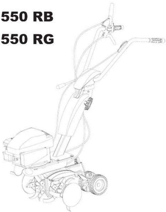
SRC 550 RB SRC 550 RG
ISTRUZIONI D'USO IT.....8
OPERATING ISTRUCTIONS E N...14
MODE D'EMPLOI FR.....20
UPUTE ZA UPORABU HR....110
NAUDOJIMO INSTRUKCIJOS LT.....116
EKSPLUATĀCIJAS INSTRUKCIJAS LV....122
INSTRUCTIUNI DE UTILIZARE RO...128
ИНСТРУКЦИИ ЗА УПОТРЕБА BG...134
KASUTUSJUHEND ET....140
NÁVOD NA OBSLUHU SK....146
İŞLETIM TALIMATLARI TK....152


INTRODUZIONE
natural_image
Diagram of a mechanical lever mechanism with two curved arrows indicating rotational motion (no text or symbols)Translation of original user instructions
Introduction
Dear Customer:

Serious risk for operator and bystander safety.
Thank you for your confidence in purchasing our products. We wish you to enjoy using our machines.
The following working instructions have been issued to ensure you a reliable running from the beginning. If you carefully follow such information the machine will operate with complete satisfaction have a long service life.
Our machines are tested under the most severe conditions before being put into production and are subjected to strict continuous tests during manufacturing stages.
The present unit has been tested in the country of origin by independent testing authorities in accordance with strict work norms and safety standards. When required, only original spare parts must be used to maintain guaranteed function and safety levels.
The operator forfeits any claims which may arise, if the machine shows to be fitted with components other than original spare parts. Subject to changes in design and construction without notice.
For any questions or further information and spare part orders, we need to be informed of the unit serial number printed on the side of the machine.
IDENTIFICATION DATA (Fig. 1) The tag plate with the machine data and Serial N° is on the left side of the cultivator under the engine. Note -Always state your motor cultivator serial number when you need Technical Service or Spare Parts.
CONDITIONS OF USE AND LIMITATIONS OF USE
This motor-hoe is designed and built to hoe the land. The motor-hoe must only be used with original equipment and spares. Any use other than those described above is prohibited and will involve, in addition to cancellation of the warranty, serious risk for the operator and bystanders.
SAFETY PRECAUTIONS
Attention: Before assembly and putting into operation, please read the operating instruction carefully. Persons not familiar with these instructions should not use the machine.
1- Persons who are not familiar with the operating manual, as well as children, adolescents under the age of 16 and persons under the influence of alcohol, drugs or medication must not operate the mower.
2 - The unit was designed in order to be used by 1 trained operator only. The person using the mower is responsible for any accidents involving other persons or their property. When operating the machine, the user should ensure that no others, particularly children, are standing in the area (10 mt.).
3 - Before starting to mill, remove any foreign bodies from the soil. Work only in daylight or in good artificial light.
4 - Do not start the machine if standing in front of the rotary cutter, neither get near the machine when working. If pulling the starter short rope, the rotary cutter and the machine have to standstill (if rotation is experienced, take action on the belt stretcher control nut).
5 - During working operations, for protection purposes, it is recommended to wear technical/strong shoes and long trousers. Be careful, because when machine is operating the danger to be wounded in the toes or feet is really high. Walk, never run with the machine.
6 - During the machine transport and all the maintenance, cleaning, equipment change operations, the engine must be switched off.
7 - Before leaving the machine, please switch the engine off.

8 - Do not switch the machine on in closed rooms/areas where you can have carbon monoxide exhalations.
9 - WARNING !! The petrol/gasoline is highly inflammable. Store fuel only in containers specifically designed for the storage of such materials. Don't fill the tank neither in closed areas, nor when engine is on, don't smoke and be careful to the petrol/gasoline loss from the tank. In case of leak, don't try to switch the engine on but move the machine away from the area in order to avoid ignition source until the gasoline vapours fade away. Re-place the tank caps and the gasoline box. Never open the cap of the fuel tank, or add fuel, while the engine is running or the unit is hot.

10 - Keep attention to the exhaust pipe. The parts near the pipe can reach 80°C.
Replace the defective and/or worn out silencers Burn hazards !!!.

11- Don't use the motor hoe on steep slopes: it could overturn!. On slope it is recommended to work crosswise, neither in slope nor in descent and be vary careful during any change of direction.
12 - Before putting the machine into operations, check it visually and make sure all the accident prevention measures are working. It is absolutely forbidden to exclude and/or to tamper with them. Replace worn or damaged elements.
13 - In case the machine is incorrectly used, and/or the repairs are performed by non-authorized technical staff, and/or fitted by spare parts other than original ones: any use other than that described above is prohibited and will involve the cancellation of the warranty and the refuse all responsibility from the manufacturer.
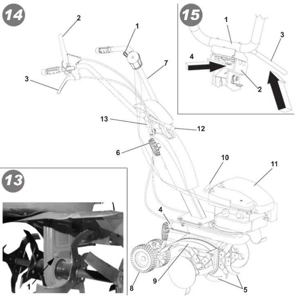
SAFETY FEATURE (Fig. 14) All motor-hoes are provided with a safety feature which acts. The device causes the transmission to disconnect automatically anytime the respective control levers are released (2 Forward speed – 3 Reverse speed).
NOTES ON HOW TO WORK WITH THE MOTOR-HOE With the engine running, rest the tines on the ground, and firmly holding the motor-hoe, insert the spur into the soil. Lower the clutch lever (Fig. 14 part. 2) on the handlebar to allow the disks to bite into the soil. The motor-hoe will move forwards when the handlebars are used to slightly lift the disks. The spur arm must always remain in the soil during work. Uses: Light or medium textured soil working. Soil working (hoeing/breaking-up). Soil tillage (weeding). Ploughing in compost or fertilizers, etc. Attention: The motor-hoe is unsuitable for working in soils covered by thick grass/lawns. It is also unadvisable to use the implement on stony soils.
TRANSPORT A forklift truck should be used to move the machine. The forks should be opened as far as possible and inserted into the pallet. The weight of the machine is given on the Manufacturer's data plate together with the other technical information. Motor-hoe can be transported to given place by means of transport wheel (Fig 14 part. 8). Switch off the engine before transporting the machine.
HOW TO ASSEMBLE YOUR MOTOR-HOE Unless otherwise agreed, the motor-hoe is delivered disassembled and placed in a packing case. For assembly to be completed, the step by step procedure is as follows :
FITTING THE DREWBAR (Fig. 2-3) Fit the long side of the drewbar (Fig. 2 part 1) into the end part of the frame arm and lock in place by turning the handle (2). The purpose of the transfer wheel (Fig. 3 part 1) is for transporting the motor hoe only. This can be fitted after turning the drewbar by 180^ and locking it in place with the wing screw (2). During motor hoe operation, the wheel should be removed: loosen the wing screw, take off the drewbar and reposition it turned round as in Fig. 2

EN
HOW TO ASSEMBLE THE HANDLEBAR SUPPORT AND HANDLEBAR (Fig. 4) assemble the handlebar support (1) on the tiller using the four screws (2) which are already placed on the plate, washers (3) and nuts (4). Assemble the wire holder (5) as shown in the pict. To assemble the handle (6) to the handlebar support (1) perform the following steps: pass the screw (7) in the top hole into the wire holder (8) in which the wires have already been placed, then secure it with the nut (9). Use the screws for the lower slot (10) into the knobs (11) and washers (12). All the mentioned pieces for mounting the handlebar, with the exception of the wire holder (8), can be found into the loose parts bag inside the box packaging. To fix the handle (6) to the corresponding support (14), you need to lower the lever (13).
CONTROL CABLES ASSEMBLY (Fig. 5 - Fig. 6): The two cables are already installed on the unit and must be connected to the corresponding levers. FORWARD (Fig. 5) Insert the wire (1) with the terminal T-slot (2) of the lever (3) pre-mounted on the handlebar. Place the cylindrical terminal (4) into the seat of the lever (3) and give a firm tug to lock it. Then pinch the wire adjuster (5) into the seat (A) of the lever, by doing downward pressure. REVERSE (Fig. 6): Insert the wire (1) marked with R label and the cylindrical terminal into the slot (2) of the lever (3) pre-assembled on the handlebar. Place the cylindrical terminal (4) into the central seat (A) of the lever (3) and give a firm tug to lock it. Then insert the log thread (5) into place (B) of the lever.
THROTTLE ASSEMBLY (Fig. 7) The throttle wire is already mounted both on the engine inside the throttle device (1). Such a device is fastened in the hole (A) of the handlebar with the screw (2) and locked with the nut (3).
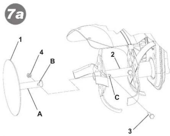
HOW TO ASSEMBLE THE TREE SAVER DISKS (Fig. 7A) Remove from the packing box the two tree saver disks (1). Insert the pin (A) in the rotavator (2) up to make the holes (B) and (C) to match each other. Secure the whole with screw (3) and nut (4). Repeat the same operation for the other disk.
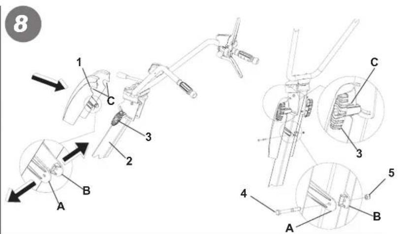
HOW TO ASSEMBLE THE TUBE COVER FOR THE HANDLEBAR SUPPORT (Fig. 8) Remove the cover (1) from the packing box, catch it to the support tube handlebar (2) extending the flaps (A) and (B), making sure the seats (C) to match with the knobs (3). Complete the fastening by passing the screw (4) into the holes of the flaps (A) and (B), and tighten using the nut (5).
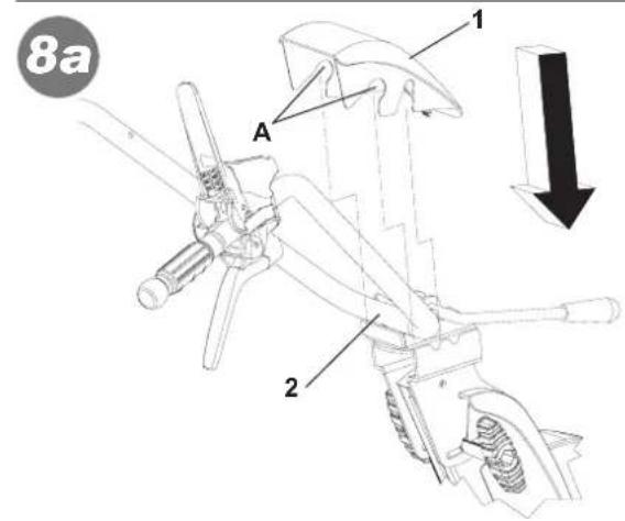
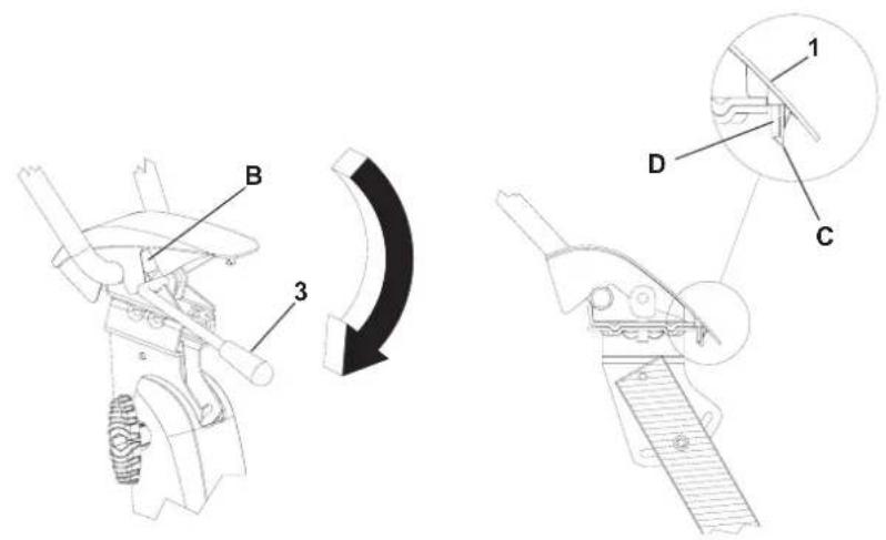
HOW TO ASSEMBLE THE HANDLEBAR COVER (Fig. 8 A) Take the cover from the packing box (1). Place it making the seats to fit each other (A) on the lower part of the handlebar (2). Turn the cover as shown in the picture, making sure it matches with the lever (3). The cover is properly installed when the hook (C) of the cover (1) is tightened to the pin (D) of the handlebar (2).
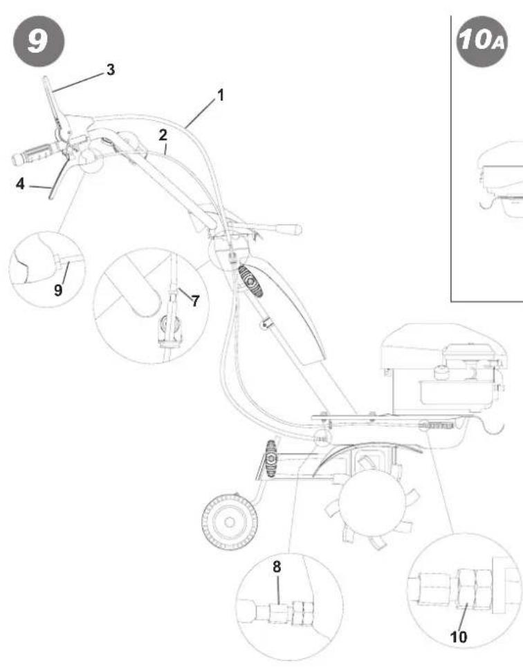
CONTROL ADJUSTMENT : (Fig. 9) Attention! The rotavator has to start working only after having operated on the control levers. Such operation can be performed by acting on the handlebar cables (1 Forward speed) 2 (Reverse speed) register. Furthermore the lever controlling the digging speed (3) should start the rotavator only after having performed half its way. When the lever (3) and the lever (4) are held together, i.e. on working operation, the belt stretcher load-spring for forward speed (5e 6) should be extended for about 8-10 mm. If the handlebar register is not enough to obtain any conditions, please go on another adjustment.
FORWARD: screw or unscrew the adjuster (7) or (8) on the wire (1).
REVERSE: screw or unscrew the adjuster (9) or (10) on the wire (2).

HANDLEBAR ADJUSTMENT (Fig. 10A - 10B) The motor-hoe handlebar can be both side and height adjusted. Before starting any work it is a good standard operating procedure to adjust the handlebar to the operator's requirements so that the machine could be easily handled.
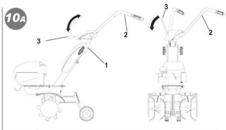
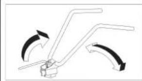
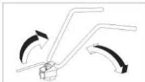
LATERAL ADJUSTMENT (Fig. 10A): The lateral inclination of the handlebar allows the operator to keep off the cultivated ground and not to squash the vegetation around. Go on raising the lever (3) to unlock the handlebar (2) from the support (1). Turn the handlebar to the desired part and lower the lever (3) to lock it.
HEIGHT ADJUSTMENT (Fig. 10B): in order to unlock the handlebar (2) you need to turn the handles (4) to loosen them
Raise or lower the handlebar in the desired position (the standard adjustment is at the sides height/level). To settle the right position, tighten the 2 handles.
INSTRUCTIONS Following the assembly & adjustment operations the motor-hoe is ready to start working.
- Adjust the handlebar to the requested position/height (see fig. 10).
- Before switching the engine on, carefully check if the motor-hoe is in perfect good repair.
- Attention: the motor-hoe is delivered without the oil into the engine. The tank has got a capacity for about 0,5 kg. and should be filled in up to the indicated level. In any case the operator should always carefully read the engine instructions manual.
- Do not change the calibration of the speeds control rotation device of the engine in order not to over-speed it.
IMPORTANT : at the first use of the machine it is absolutely necessary to verify that inside the chassis to be present the lubrication oil. Do no start the unit/machine on before having done such control.
- When you have finished the assembly, switch the motor-hoe on and check, bringing the accelerator to stop position, the engine to shut completely down.
- How to switch the engine on (Fig.14): Open the fuel cap (for the engine equipped like this), push to START the accelerator lever on the handlebar (1). If the engine is cold, operate the starter device on the carburettor, bring the starter handle (10) and pull energetically.
When the engine is on, after some bursts/bangs, put the starter again at rest position.
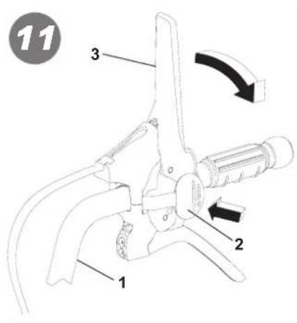
- Forward speed (fig.11): Grip the handlebars (1) and press the safety device (2) which is preventing the accidental tines connection. Lower the forward lever (3) all its way long.
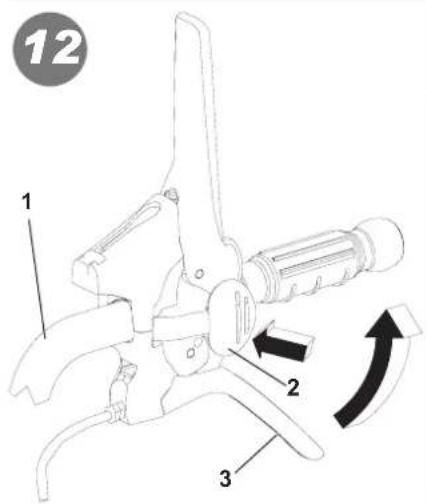
- Reverse speed (Fig. 12): Grip the handlebars (1) and press the safety device (2) which is preventing the accidental tines connection. Pull the reverse lever (3) all its way long.
The present machine has been projected in order to lower to the minimum the vibrations and noise levels. Anyhow we can advise you to stop working any now and then in case you would need to perform/work for a long period.
- Stop working operation : To stop the work, switch the engine off, bring the accelerator lever (Fig. 14 part 1) into stop position.
CHANGING THE OIL IN THE LOWER DRIVE (Fig. 13) Generally speaking, the oil should be changed every 100 work hours (oil viscosity SAE 80). Proceed as follows: A) loosen the screw cap (1). B) place the machine at an angle and suck up the oil using a syringe. C) fill up with about 0.5 litres of new oil.
To check the oil level: Place the machine in horizontal position; unscrew the cap and make sure the oil is at the lowest level of the hole. The filler and emptying cap corresponds to the level of the oil.

ATTENTION! The used oil must not be drained into the sewer system or waterworks. In order to prevent any pollution to the water-table. Most garages have used oil deposits, or use the authorized deposits according to your local authority regulations.
GARAGING AND SCHEDULED MAINTENANCE (Fig. 15) Keep attention that all the nuts, screws and bolts are tightened in order to guarantee a good machine working on safety conditions. Leave the machine to cool before garaging anyhow don't room it if the tank still contains some fuel as the vapours could reach some blazes or sparks. The fuel tank is to be drained outdoors only. To lower the fire danger, keep the engine, the silencer and the fuel area free from leaves, grass or greasy substances. Periodically check the tightness of the handlebar (1) to the support (2). If the tightening is not guaranteed, please lower the lever (3) and tighten the nut (4).
DESCRIPTION OF CONTROLS (Fig. 14) 1. Throttle lever - 2. Hoeing gear control lever (safety feature) - 3. Reversing lever - 4. Tilling adjustment spur (single position) - 5. Cultivator blade (with enlargement) - 6. Knobs handlebar/frame - 7. Handlebar - 8. Transport Wheel - 9. Hoe shield - 10. Pull-out handle (self-winding device) 11. Motor - 12. Lock/release lever for handlebar - 13. Handlebar support
TECHNICAL SPECIFICATION Engine: consult the specific publication for information. Working width 50 cm. The highest speed of rotation of the tiller is about 120 R.P.M. Transmission : single speed + reverse speed. Weight of the complete motor-hoe is 42 kg. Max length: 1,3 m. Max width: 0,50 m. Height: 1,10 m. Package dimensions: long 80 cm - wide 53 cm - high 69 cm.
NOISE AND VIBRATION LEVEL Measured sound power level with En709, Lwa = 94.3 dB (A). Handlebar vibration in compliance with EN 709 and ISO 5349. Level max detected = 18 m/s ^2 .
ACCESSORIES: Ridging plough.
TROUBLESHOOTING

Before performing any maintenance and clearing work operation, please take the spark-plug cap off.!
| FAULT FAULT CLEARANCE | |
| The engine does not start Check the fuel level, if necessary | refuel. |
| Check the throttle to be on START position. | |
| Check the spark-plug connector to be properly attached. | |
| Check the spark-plug condition and if necessary replace it. | |
| Check the fuel valve to be in the opened position( only for the models showing such feature). | |
| The engine power goes down The air filter is dirty – please | clean it. |
| Check if any stone or soil/vegetation residue is stopping the tines rotation, in case clean them. | |
| The tines are not rotating Adjust the transmission cables registers. | |
| In case you are not able to remedy the defect/damage according to a.m. table, please contact an authorized service center only . | |

Read the instructions manual before operating on the machine - Danger tiller rotation
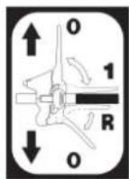
Forward and reverse drive label
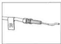
Label for reverse wire


STOP
natural_image
Diagram of a mechanical lever mechanism with three blades and directional arrows indicating motion (no text or labels)1 Manufacturer
2 Type
3 Year of construction
4 Serial number - Progressive
5 Mass
6 Power in kW
Sticker handlebar rotation
F
Introduction

STOP Plaquette acceleration
natural_image
Diagram of a mechanical lever mechanism with curved arrows indicating motion (no text or symbols)Plaquette rotation mancherons

natural_image
Diagram of a mechanical lever mechanism with three curved arms and directional arrows indicating motion (no text or symbols)Aufkleber Holmdrehung
INTRODUCCIÓN
Estimado cliente,
natural_image
Diagram of a mechanical lever mechanism with curved arrows indicating motion (no text or symbols)natural_image
Diagram of a mechanical lever mechanism with curved arrows indicating motion (no text or symbols)natural_image
Pure mechanical diagram showing a lever mechanism with curved arrows indicating rotation (no text or symbols)natural_image
Diagram of a mechanical lever mechanism with curved arrows indicating motion (no text or symbols)natural_image
Diagram of a mechanical lever mechanism with curved arrows indicating motion (no text or symbols)natural_image
Diagram of a mechanical lever system with curved arrows indicating motion (no text or symbols)natural_image
Diagram of a mechanical lever mechanism with curved arrows indicating motion (no text or symbols)1 Produsent
2 Modell
3 Konstruksjonsår
4 Serienummer - Progressiv
5 Masse
6 Effekt i kW
Etikett rotasjon styrehåndtak

ÚVOD
natural_image
Pure mechanical diagram showing a lever mechanism with curved arrows indicating motion (no text or symbols)natural_image
Diagram of a mechanical lever mechanism with curved arrows indicating motion (no text or symbols)natural_image
Diagram of a mechanical lever mechanism with curved arrows indicating motion (no text or symbols)natural_image
Diagram of a mechanical lever system with three curved arrows indicating rotational motion (no text or labels)natural_image
Diagram of a mechanical lever mechanism with curved arrows indicating motion (no text or symbols)natural_image
Diagram of a mechanical lever mechanism with curved arrows indicating motion (no text or symbols)natural_image
Diagram of a mechanical lever mechanism with curved arrows indicating motion (no text or symbols)natural_image
Diagram of a mechanical lever mechanism with curved arrows indicating motion (no text or symbols)natural_image
Diagram of a mechanical lever mechanism with curved arrows indicating motion (no text or symbols)natural_image
Diagram of a mechanical lever mechanism with curved arrows indicating motion (no text or symbols)natural_image
Pure mechanical diagram showing a lever mechanism with curved arrows indicating motion (no text or symbols)natural_image
Diagram of a mechanical lever mechanism with curved arrows indicating motion (no text or symbols)natural_image
Diagram of a mechanical lever mechanism with multiple arms and directional arrows indicating motion (no text or symbols)natural_image
Diagram of a mechanical lever system with three curved arms and directional arrows indicating motion (no text or labels)1 Proizvođač
2 Model
3 Godina proizvođenja
4 Serijski broj artikla- Progresivni
5 Težina
6 Snaga izražena u kW
Etiketa za rotaciju ručke
02/2022 cod. 37.0065.009