ATC Fp - Pump Kärcher - Free user manual and instructions
Find the device manual for free ATC Fp Kärcher in PDF.
User questions about ATC Fp Kärcher
0 question about this device. Answer the ones you know or ask your own.
Ask a new question about this device
Download the instructions for your Pump in PDF format for free! Find your manual ATC Fp - Kärcher and take your electronic device back in hand. On this page are published all the documents necessary for the use of your device. ATC Fp by Kärcher.
USER MANUAL ATC Fp Kärcher
Environmental protection 5
Accessories and spare parts.. 6
Safety instructions.. 6
Initial startup.. 6
Operation 6
Settings 7
Frost protection 7
Shutting down 7
Care and service 7
Transport 8
Storage 8
Troubleshooting guide 8
Warranty 8
Technical data. 9
EU Declaration of Conformity 9
General notes

Read these original instructions and the safety instructions chapter before using the
device for the first time. Act in accordance with them.
Keep them safe for future reference or for future owners.
Environmental protection
The packing materials can be recycled. Please dispose of packaging in accordance with the environmental regulations.
Electrical and electronic appliances contain valuable, recyclable materials and often components such as batteries, rechargeable batteries or oil, which - if handled or disposed of incorrectly - can pose a potential threat to human health and the environment. However, these components are required for the correct operation of the appliance. Appliances marked by this symbol are not allowed to be disposed of together with the household rubbish.
Notes on the content materials (REACH) Current information on content materials can be found at: www.kaercher.com/ REACH
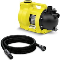
Accessories and spare parts
Only use original accessories and original spare parts. They ensure that the appliance will run fault-free and safely. Information on accessories and spare parts can be found at www.kaercher.com.
Safety instructions
Hazard levels
△DANGER
- Indication of an imminent threat of danger that will lead to severe injuries or even death.
WARNING
- Indication of a potentially dangerous situation that may lead to severe injuries or even death.
CAUTION
- Indication of a potentially dangerous situation that may lead to minor injuries.
ATTENTION
- Indication of a potentially dangerous situation that may lead to damage to property.
General
To avoid danger to persons, animals and property, it is imperative to read and observe the following documents before operating the device:
- Operating instructions
- All safety instructions
The respectively applicable national regulations
In self-service operation, the operator must ensure that the users are informed by means of clearly visible information notices:
Potential dangers
- Safety devices
- Operating the device.
Operation
△WARNING
Children over the age of 8 and persons with reduced physical, sensory or mental capabilities, or those with a lack of experience and knowledge, are only allowed to use the appliance if they are properly supervised, have been instructed with respect to using the appliance safely by a person responsible for their safety, and understand the resultant dangers involved.
Children must not play with the appliance.
- Cleaning and user maintenance may not be carried out by unsupervised children.
Always keep the area around the device clean and free of oil and grease.
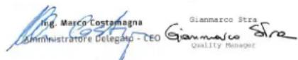
Behaviour in the event of an emergency
- In the event of an emergency, push the STOP button.
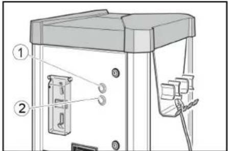
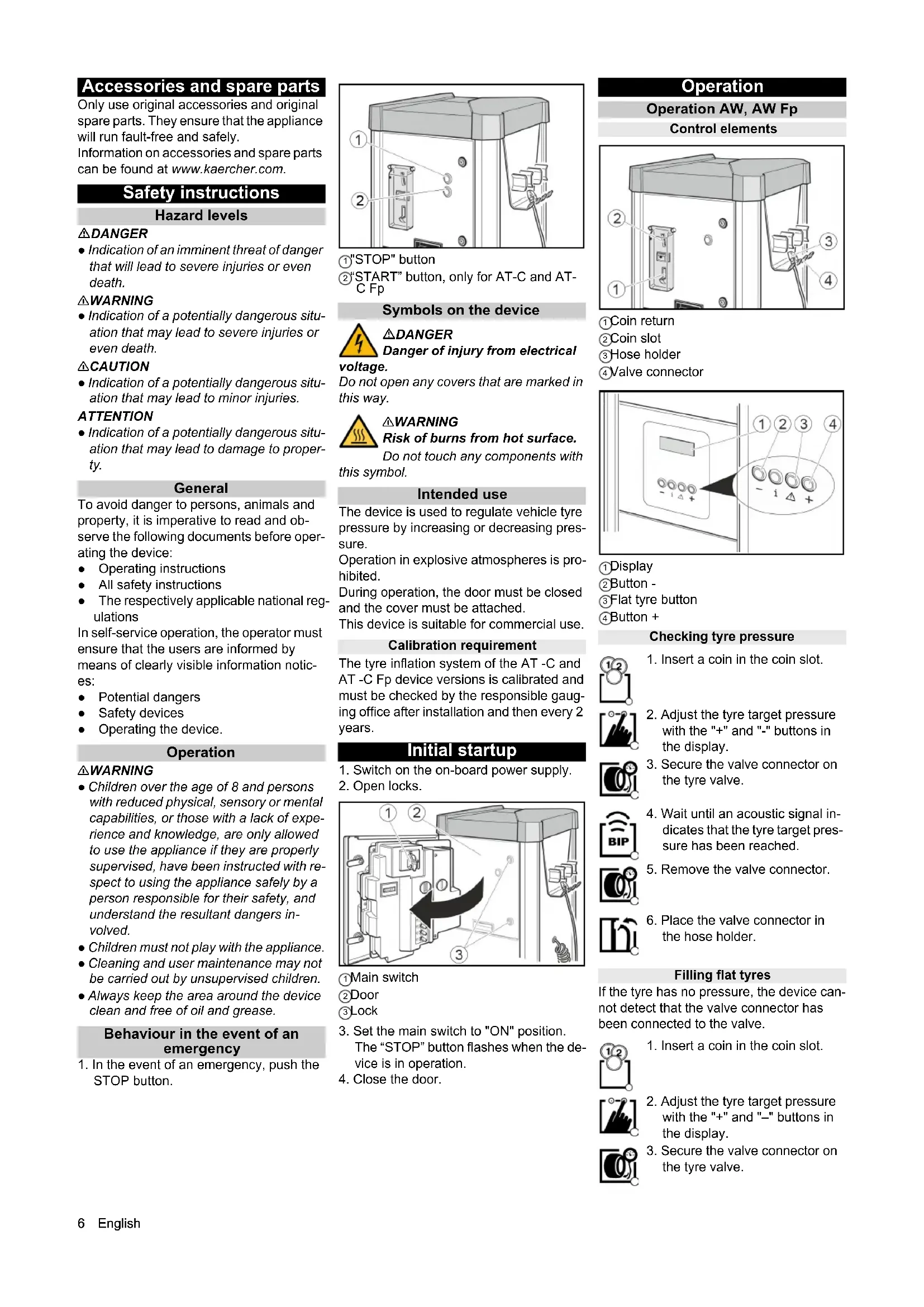
(1) "STOP" button
②"START" button, only for AT-C and AT-C Fp
Symbols on the device

△DANGER
Danger of injury from electrical
voltage.
Do not open any covers that are marked in this way.

△WARNING
Risk of burns from hot surface.
Do not touch any components with this symbol.
Intended use
The device is used to regulate vehicle tyre pressure by increasing or decreasing pressure.
Operation in explosive atmospheres is prohibited.
During operation, the door must be closed and the cover must be attached.
This device is suitable for commercial use.
Calibration requirement
The tyre inflation system of the AT-C and AT-C Fp device versions is calibrated and must be checked by the responsible gauging office after installation and then every 2 years.
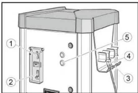
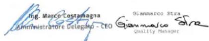
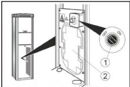
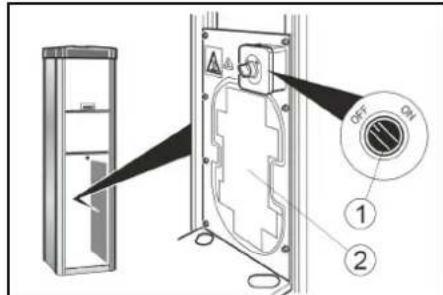
Initial startup
- Switch on the on-board power supply.
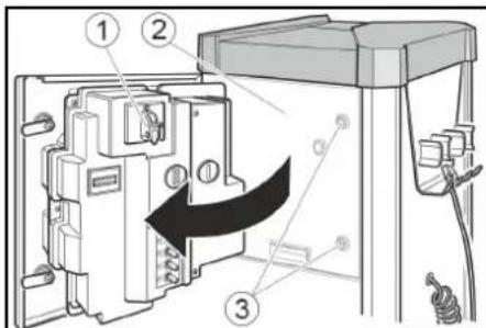
- Open locks.
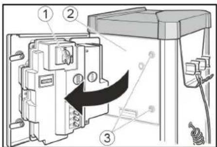
Main switch
②Door
③Lock
- Set the main switch to "ON" position. The "STOP" button flashes when the device is in operation.
- Close the door.
Operation
Operation AW, AW Fp
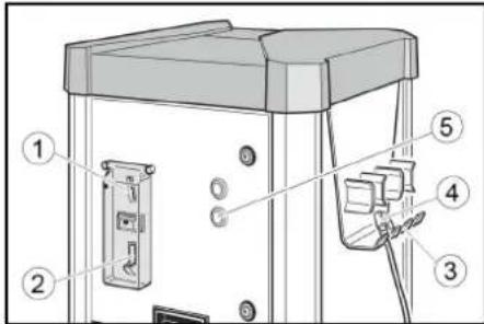
Control elements
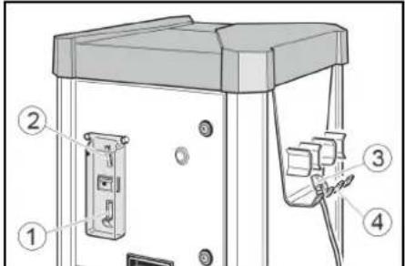
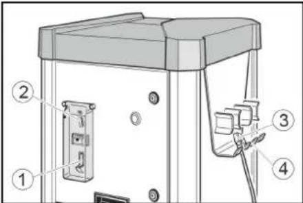
Coin return
Coin slot
③ Hose holder
④ Valve connector
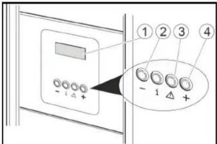
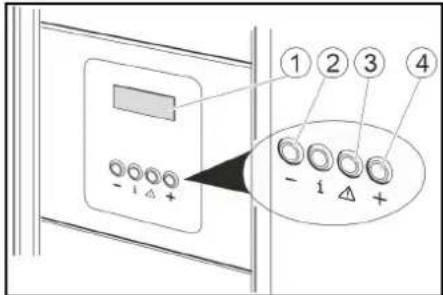
Display
②Button -
③ Flat tyre button
4Button +
Checking tyre pressure


- Adjust the tyre target pressure with the "+" and "-" buttons in the display.
-
Secure the valve connector on the tyre valve.
-
Wait until an acoustic signal indicates that the tyre target pressure has been reached.
- Remove the valve connector.

- Place the valve connector in the hose holder.
Filling flat tyres
If the tyre has no pressure, the device cannot detect that the valve connector has been connected to the valve.

- Insert a coin in the coin slot.

- Adjust the tyre target pressure with the "+" and "-" buttons in the display.
- Secure the valve connector on the tyre valve.

- Press the "Flat tyre" button.
- Wait until an acoustic signal indicates that the tyre target pressure has been reached.
- Remove the valve connector.


- Place the valve connector in the hose holder.
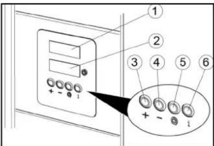
Operation AW-C, AW-C Fp Control elements
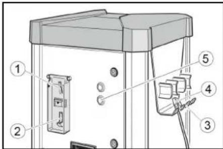
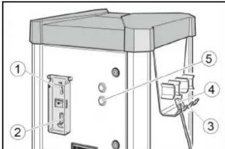
Coin return
(2)Coin slot
3Hose holder
(4)Valve connector
⑤START button
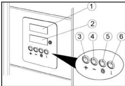
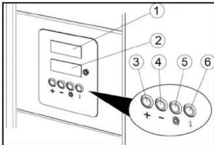
①Target pressure display
(2) Tire pressure display
3Button+
4Button -
Flat tyre button
No function
Checking tyre pressure


- Insert a coin in the coin slot.
- Press the START button.

- Set the target tyre pressure with the + and - buttons in the target pressure display (upper display).
- Secure the valve connector on the tyre valve. The tyre pressure display (lower display) shows the tyre pressure

- Wait until an acoustic signal indicates that the tyre target pressure has been reached.
- Remove the valve connector.

- Place the valve connector in the hose holder.
Filling flat tyres
If the tyre has no pressure, the device cannot detect that the valve connector has been connected to the valve.

- Insert a coin in the coin slot.

- Press the START button.

- Set the target tyre pressure with the + and - buttons in the target pressure display (upper display).

- Secure the valve connector on the tyre valve.
The tyre pressure display (lower display) shows the tyre pressure.
- Press the "Flat tyre" button.

- Wait until an acoustic signal indicates that the tyre target pressure has been reached.

- Remove the valve connector.

- Place the valve connector in the hose holder.
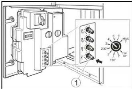
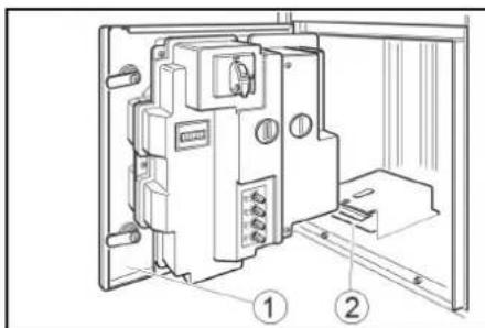
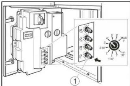
Settings
Setting the run time
Note
The adjustable run time applies to the insertion of one of the following coins:
50 Eurocents
50 British pence
1 Swiss franc
1 Polish zloty
5 Norwegian Kroner
Customer Service can set up different types of coins.
- Set the run time with the P I rotary knob. Possible setting range of 30 seconds to 7 minutes.
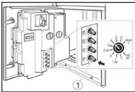
①Rotary knob P1
Note
Rotary knobs P II, P III and P IV have no function.
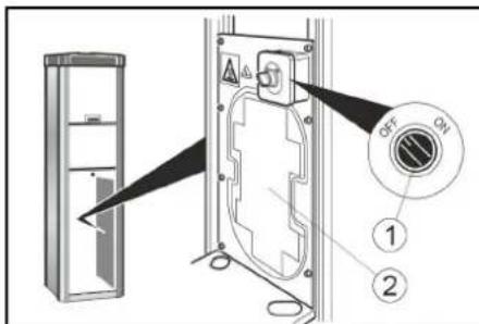
Frost protection
Device with frost protection
- Turn the frost protection switch "ON" at temperatures below +5^ .
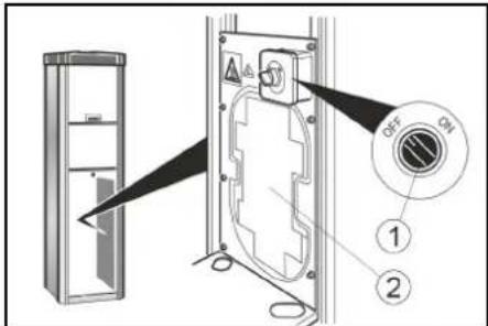
Frost protection switch
(2) Frost protection heater
ATTENTION
Risk of damage
The frost protection is active only when the main switch is "ON".
When activating the frost protection, check whether the main switch is in the "ON" position.
Note
The frost protection heater is not thermostat-controlled. When switched on, the heater is continuously in use.
Device without frost protection
In a device without frost protection, a shutdown must be carried out if there is risk of frost.
Shutting down
- Drain the condensate in the compressed air tank (see "Maintenance tasks").
- Set the main switch to the "OFF" position.
Care and service
Daily
- Empty the coin cassette (see "Maintenance tasks").
- Check the general condition of the device.
- Check the condition of the valve connector.
- Check the condition of the hose line.
- Open the lower cover and check the condition of the compressor.
- Have damaged parts replaced.
Weekly
- Clean the outside of the device
- Drain the condensate in the compressed air tank (see "Maintenance tasks").
Service very 2 years
Only with AT-C,AT-C Fp
- Have the pressure measuring device of the tyre inflator calibrated by the gauging office.
Maintenance work
Emptying the coin cassette
- Open the door.

Door
② Coin cassette
2. Remove and empty the coin cassette.
- Remove the cover.
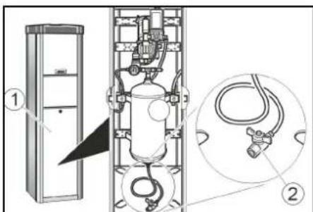
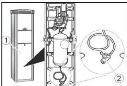
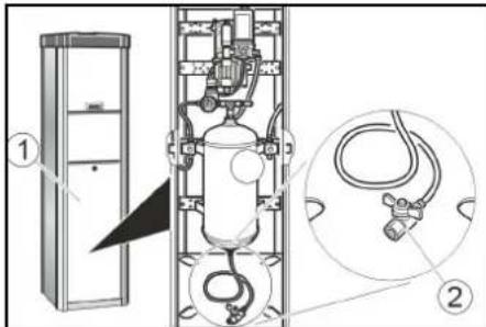
Drain the condensate
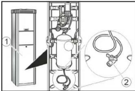
1Bar cover
②Condensate drain valve
2. Hold the condensate drain valve over a shaft or collecting container.
△WARNING
Risk of injury, risk of damage
The water stream escaping from the condensate drain valve can cause injury or damage.
Never point the condensate drain valve at people, animals, the device or electrical components.
3. Slowly open the condensate drain valve and drain the condensate.
4. Close the condensate drain valve.
5. Attach the cover.
Transport
CAUTION
Risk of injury, risk of damage
Be aware of the weight of the device during transportation.
- When transporting in vehicles, secure the device against slipping and tipping over according to the applicable guidelines.
Storage
CAUTION
Risk of injury and damage
Be aware of the weight of the device during storage.
Troubleshooting guide
△DANGER
Danger from electric shock.
Before working on the device, set the main switch to "OFF" and disconnect the onboard power supply.
The device does not work
- Check the on-site voltage supply.
- Set the main switch to "ON" position.
- Contact customer service.
The device does not start after the valve connector has been connected to the tyre.
-
Check that the valve connector is seated correctly.
-
Check the condition of the hose and of the valve connector.
Press the "tyre flat" button.
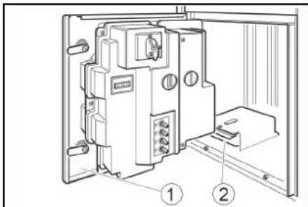
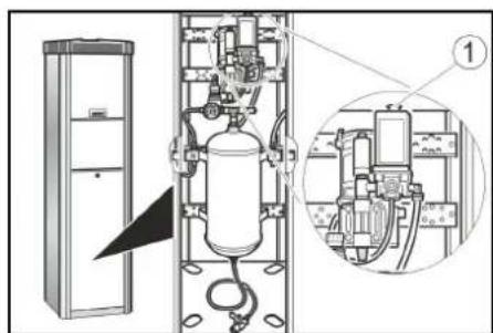
There is no compressed air
Pull the compressor on-button upward.
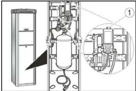
① Compressor on-button
The compressor is overheated: Wait until the compressor has cooled off.
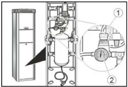
The tyre pressure is too low
- Check the pressure on the pressure gauge. Readjust the pressure reducer if necessary.
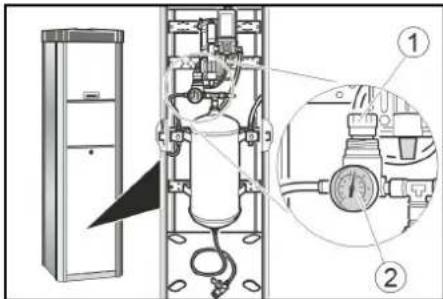
Pressure reducer
② Pressure gauge
Malfunctions with information shown on the display
| Fault Cause Rectification | ||
| ER1 Unstable pressure measurement due to defective valve connector or hose | Replace the valve connector. Replace the hose. | |
| ER2, ER7 The tyre pressure is too low. Unstable pressure measurement due to defective valve connector or hose. | Check the tyre pressure on the pressure gauge and readjust the pressure reducer if necessary. Replace the valve connector. Replace the hose. | |
| ER3 | The tyre pressure is too low. | Check the pressure on the pressure gauge and read-just the pressure reducer if necessary. |
| ER4 | The tyre pressure is too high. | Check the pressure on the pressure gauge and read-just the pressure reducer if necessary. |
| ER5 | The voltage supply is disturbed. | Contact customer service. |
| ER6, ER8, ER9, ERU, ERB | Malfunction in the electronics. | Contact customer service. |
| ERP | The valve connector came loose during inflation. The tyre pressure is not stable. | Check that the valve connector is seated correctly. Check the pressure on the pressure gauge and read-just the pressure reducer if necessary. |
Warranty
The warranty conditions issued by our relevant sales company apply in all countries. We shall remedy possible malfunctions on your appliance within the warranty period free of cost, provided that a material or manufacturing defect is the cause. In a warranty case, please contact your dealer (with the purchase receipt) or the next authorised customer service site. (See overleaf for the address)
Technical data
Electrical connection
Mains voltage V 230
Phase 1
Frequency Hz 50
Power rating W 450
Degree of protection IP44
Compressed air
Flow rate I/min 100
Pressure MPa 0,1..0,8
Ambient conditions
Temperature with frost ^ C -10...+40 protection
Temperature without ^ C +5 +40 frost protection
Humidity % 10...80
Noise emission
Sound pressure level dB(A) <70
LpA
Sound power level dB(A) 76,8
LWA + K uncertaintyWA
Sound power dB(A) 4
level LWA +
K uncertaintyWA
Dimensions and weights
| Weight | kg | 55 |
| Length | mm | 423 |
| Width | mm | 423 |
| Height | mm | 1550 |
Subject to technical modifications.
EU Declaration of Conformity
We hereby declare that the machine described below complies with the relevant basic safety and health requirements in the EU Directives, both in its basic design and construction as well as in the version placed in circulation by us. This declaration is invalidated by any changes made to the machine that are not approved by us.
Product: Tyre inflator
Type:AT,AT Fp,AT-C,AT-C Fp
Currently applicable EU Directives
2006/42/EC
2014/35/EU
2014/30/EU
Documentation supervisor: Gianmarco Stra
MTM Hydro Srl
Via Moglia, 33
12062 Cherasco (Cn) - Italy
Tel. +39 0172 427311
Fax +39 0172 495437
CF / RI / P.IVA / VAT: IT 02469390047
Cap. Soc. €255,000 - REA CN-178422
CCIAA
info@mtmhydro.it
PEC: mtmhydro@multippec.it
www.mtmhydro.it
Cherasco, 2018/09/01
Contenu
Remarques generales 9
12062 Cherasco (Cn) - Italy
Tel. +39 0172 427311 Fax +39 0172 495437
C.F./R.I./P.IVA/V.A.T.: IT 02469390047 Cap. Soc. € 255.000 - REA CN-178422 CCIAA
info@mtmhydro.it
PEC ^ : mtmhydro@multipec.it www.mtmhydro.it
Cherasco, 2018/09/01
Indices
12062 Cherasco (Cn) - Italy
Tel. +39 0172 427311
Fax +39 0172 495437
C.F./R.I./P.IVA/V.A.T.: IT 02469390047
Cap. Soc. 255 000 € - REA CN-178422
CCIAA
info@mtmhydro.it
PEC: mtmhydro@multipec.it
www.mtmhydro.it
Cherasco, 01/09/2018
Indhold
www.kaercher.com/REACH
EpaiozTe autcTis oynies.
duaeteautesTisodnyiesyia
12062 Cherasco (Cn) - Italy
Tel. +39 0172 427311
Fax +39 0172 495437
C.F./R.I./P.IVA/V.A.T.: IT 02469390047
Cap. Soc. € 255.000 - REA CN-178422
CCIAA
info@mtmhydro.it
PEC: mtmhydro@multippec.it
www.mtmhydro.it
Cherasco, 2018/09/01
Icindekiler
Genel uyarilar 45
Cevre koruma 45
IpeepnepBbIM npmmeHHeNEMyCTPOCTBA O3HaKOMNTbCcDaHHoOpnHaJIbHOI
HCTpyKneI NO 3KnIyataunn I rnaBOO TeXnke 6e3oNaCHOCTN. DeiCTBOBaTb B COOTBETCTBN C HMM.
CoXpaHbI IN IIN DaJIbHeIWeI OINb3OBAHnI INI DnI CNeDyIOUeBOBlaDeNbua.
3aunTa okpykaUoien cpebl

YnakoobHbIe MaTePnaJIbI NODaIOCTcB TOpunHNo Inepepa6OtKe. YnakoBky 5xOIMo yTINm3NpObaTb 6e3 yUepe6aOKpyKaIOSeI cpebl.

3neKtpnuecknE n 3neKtpoHHbIe yctpoiCTBa qacto coedePKat ceHHbIe MaTePnAJIbI, pNtOndHbe DnA
BtopnHno nepepa6tKn, n 3aacctyIO
Takne KOMNoHEtbl, KaK 6atapen,
AkkymJrTopbI ININ MacNO, KOtOpBie npN
He npabInbHom o6paueHNn ININ
HeHaJIeKaUe yTNIN3aun
IpeCTabJIHToNToNEuJaIbHyIO NaCHOCT
IIra 3IopOBBa n 3KOnOIIN. TeM He MeHee
DaHHbIE KOMNoHEtbl He06XoDMbl DnI
npabInbHO pa6bI yCTpOCTBA.
YCTpOCTBA, 603NaueHHbIe 3TIM
CmBONOM, 3anpeSeHO yTNIN3nPOBaTb
BMecTe C 6bITOBbIMN OTXODAMN.
Yka3aHnno nHrpeDneHTam (REACH)
IINyueHnraAkyaIbHOInHfOpMaun
o6 nHrpeDneHTax cm. www.kaercher.com/ REACH
PpHaJTeJXHocTn 3anaChbIe Yactn
IcnoIb3oBaTbToIbKO opnHnHaIbHbIe npnHaIeXHOCTN 3anaChIbe YAcTn. ToIbKO OHI rapaHTnpYIO6eOanacHyIO 6ecnepeoHyIO paOty yCtpoIcTBa. DnI nOnyueHnIHOpMaunO npnHaIeXHOCTx N 3aIpaCTax CM. www.kaercher.com.
Yka3aHnno TExHnKe
6e30nachoctn
CTeneHb onachoctn
ONACHOCTb
- Yka3aHue omHocumenbHO
HnocpecmbeHHO apo3ueonachocmu, komopar npueodum Kmxeblm mpaemam unu Kcmepmu
△PENDEUYNPEKDEHNE
- Yka3aHue omHocumenbHO 603MOxHOJ NOMeHuaJIbHO onaCHO cumyaauu, KOMopaa MoXem npueecMu K mXeIbIM mpaMam UJU K Cmepmu.
OCTOPOXHO
- Yka3aHue Ha nomehuaanbHO onachyocumyaucu, Komopar MOxem npubeecmuK nonyuHuO nekuxmpaM.
BHIMAHHE
- Yka3aHue omHocumenbHO 603MOxHou NOMeuaIbHO onaHou cumyaUu, KOMopaMoxem noaney 3a cobou MamepuaIbHi yuep6.
06nne noJoxeHHa
Bo n36ekaHne onaHocn dIy IIOde, XNBOThbIX NIMyUeCTBa nepei 3KcIpyatauNei ycTpoCTBa CNeDyET 063aTeBbHO O3HaKOMITbCn INpNHrTB BHIMAHHe CNeDyUOuNE DOKymeHTbl:
HCTpyKUma NO 3KnnyatauM
BCEyka3aHnI NO TEXHnKe 6e3oNaCHOCTN;
COOTBETCTBYOUIMNHaUHOHaJIbHbIM3aKOHOdaTeJIbHbIM HOpMaM;
B pexime camoo6cnykubahnna 3KcIpyaTnpuOua CTopoHa DoJXHa o6ecneHTb HOpMnpoBaHne IOIb3OBaTeJIe C NOMOuBIO YeTKHX yka3aTeJIbHbIX TaJIueK O:
B03MOXHbIXOnaCHOCTX;
- yctpoonctba x; 6e3oNaChoctn
- ynpabBneHn ycTpoNCTBOM.
UnpaBHeHne
△NPEDYNPEXDEHNE
- Demu cmapue 8 lem u nuca c oza panueyHbIMU fu3uyeckumu, ceHCOPhbIMU uLU yMCmEeHHbIMU cnoc6hOcMmu, a makke luca, he obnaadoouue HeobxodumbIM OnbimOM u 3HaHnmu, Moaym UcnoIb3o6aMb ycmpoucmeo molko e mom cnyae, ecnu OHU haxodamr noD hadJeKauzum npucmomp uLU npouu uHcmpykmak KOMnemeHmHO2 luua omHocumelbHo 6e3onacHO2 uCNoB3o6aHur obopyoBaHUR u Oco3HaHOM B03MOXHbIE pucku.
He paapewamb demuapambc ycmpoicmb.
Oucmky umexhueeckoe 6cbnykuahe, komopoe moxem npoeodmb noIb306amelb, He pa3peuEHO bInonHnMb demm 6e3 npucMompa.
Bce2da codepkamb o6nacmb 6okpye ycmpoucmea yucmou u o63kupenHou.
NoBeHeHb Cnyae BO3HKnHOBeHn aBapnHou cnTyauu
- B abapnHcNTyaCIN HaxKaTb KHOKky «STOP»
(1)KhONka《STOP》
② KhonKa «START», toIbko Ha AT-C n AT-C Fp
CnMbOJIbHa yCTpOInCTBe

△ONACHOCTb
Onachocmb u3-3a
3neKmpuyecko0o HanpJKeHu.
He omkpbIaamb KpbIkwu c makou Mapkuopoekou.

△PENDyUNPEXDEHNE
Onachocmb oko2o6 o 2opyue noeepxnocmu.
He npukacmbcK KomnoheHmam C 3mou MapkuopOBo.
IcnoJb3ObaHne no Ha3HaueHnIO
UcpoIcTBo IpeHa3HaeHo IJnpeYIpOBaHN DaBHeHb B WInhaxABTomO6JIeN PyTeM NOKaUNBaHN nnC6pOca DaBHeHn.
3KcnnyatauBO B3pbBOONachbIX 30Hax 3anpeueHa.
Bo Bpempa6oBtI DBePca DoJXHa 6bItb 3aKpbTa N DoJXeH 6bItb yCTaHOBHeKoJxYx.
DaHHoe yCTpoIcTBOppeDyCMToPeHO dI npOMbIJIeHHoro IcNIOJIb3OBAHn.
Heo6xoJMOocTb KaJIu6pOBKn
yCTPOCTBO DnHa HakaunBaHn B Bepcnx yctpoiCTBa AT-C n AT-C Fp OKaINbPoBaHa n DoJXHa npOBeprTbcr OTBeTCTBHeHHbIMeHTPOM CTAHapTn3aUNNOCNe yCTaHOKn, a 3aTeM kKaJdbie 2 rOda.
BbOД bKcπIyatauIO
- BkIIOUHTb NCTOUYHK NITAHN NO MecTy 3KcIpyatau.
2.OTKpbItb 3AMKn
TJbAHHBm BbIKIOaTeJIb
(2)Дерца
③3aMOK
3.YctaHOBtB TnABHbBvIKUoyTeIb B noIOxKeHne ON (《BKI.》)KhONKa STOP Muraet, KOrda yCTpoiCTBO pa6OtaeT.
4.3akpbItbBepuY.
UnpaBneHne
UnpaBHeA W,AW Fp
3JemeHbI ynpaBHeHH
①Bo3BpaT MOHET
2MOHETONPNEMHNK
③Держateлшанга
4BeHTnIbHbI nTeKeP
(1)Ducnnei
YBaHHe CnYCTNBWUXC8 WHH
EcINB uHax COBCem HET DaBHeHn,TO yCTPOIcBO He MOXeT ObHapyKntb HAJIuHne BEHTINbHORO WTeKepa Ha BEHTIne.

- Bpocntb MOHETy B MOHETOpnEMNHK.

2.CnOMOJIbIO KHOJOK 已 + 日 N 已 - 日 YCTaHOBUTb Ha DCNCEE 3aDaHHoe DaBHeHne B WnHax.

3.3aKpeNITb BeHTnIbHbI WTEKEP Ha BEHTnIe WINHbI.

- HaxaTb KhONky «Cnyck LInHbl».
YnpaBHeHnE AW-C,AW-C Fp
3nemEnbI ynpaBneHn
①Bo3BpaMTMOHET
②MoHETOpnEmHHK
③ DepeKaTeNb WnHaHra
4BeHTnIbHbI WTeKeP
(5)KhoNka START

1 DnCnne 3aDaHHoro DaBHeHn
(2)Диспел徳давленившнанх
③KHOIIKa «+»
(4)KhONka «-»
⑤ Khonka «Cnyck WNHBI»
6e3yHKuN
PpOBepKa DaBHeHnB WnHax

- Bpocntb MOHETy B MOHETOpnPnEMHNK.

- HαkaTb KhONky «START»

1.HaCtpoNTb npoDOnKHTeNbHocTb pa60tbHaNoBOpOTHOpyKeP1. Bo3MOxHbI dnaIa3OH HAcTPOKn OT 30 cekyHd do7 mHyT.
① NobopoTHaŋ pyka P I
IpumeyaHue
PoeopomHbIe pyku P II, P III u P IV Heakmuehbl.
3aцит aOT 3aMep3aHnIa
YcTPOIcTBOC3aUNTOIOT 3aMep3aHnA
1.Пи TempepaTpyax Hnke+5°C NOBepHyTb BbIKIOUaTeJIb 3aIITbI OT 3aMep3aHnB N noIOxKeHne «ON» («ВКЛ.»).
① BbiknioateJIb 3aunIbOT 3aMep3AHN
② HarpeBaTeBbHbI 3JeMeHT DnA 3aUHTbI OT 3aMep3AHN
BHIMAHHE
Onachocmb nopekdeHua
3aumoma om 3amep3anu akmueHa monbko e mom cnyae, ecnu anaebiu ebIKIOyamelh haxodumc e noloxehuu «ON» («BKJ.»).
Ppu akmuauu 3auumbI om 3amep3aHua npoeepumb, Haxodumc n2naeHbI ebiknquamel b e nooxehuu «ON» («BKJ).
PpumeyaHue
HaaseamelbHbI 3nEmHm dna3aumbl om 3amep3aHua He Umeem mepmocamuueckou peeylnpoeku. Bo ekluohcHOM COcmorHuu HaaseamelbHbI 3nEmHm paobama npodokxumelbHoe epem.
YcTpoiCTBO 6e3 3aunIbI OT 3aMep3aHnA
B yctpoCTBe 63 3aunTb OT 3amep3aHn npn onacnoctn 3amep3aHn Heo6xOdmo BblONHHT npoueDpy BbIBOda n3 3Kcnnyatau.
BbIBoN3 3KcNnyataaUN
1.Cntb KOHcHcat n3 pe3epByapa dna Cxkato Bo3dyxa (cm. «Pa60tI no TexHueckOMy 06CnyKuBaHIO»).
2.YCTAHOBITbIaBbHbBbIKIOUaTeIbB NOIOXeHHe OFF (BbIKI.).
YxOД n TeXHnueCkOe 06cnyKnBaHne
EkeDHeBHO
- OnopoxHHntb kaccety dnia MOHET (CM. «Pa60tbl NO TexHnueckOMy 06cnyKnBaHnIO»).
2.Поверпь obше cocToHne yCTPOCTBA. - Поберпь соctогне BEHTINbHOrO uTekepa.
4.Поверпь союншанronpoвoda. - OTKpbTb HnXHHKOxHy INpOBepNTb COCTOHHe KOMnPecccopa.
- NobpekdeHbIe yactn 3aMeHntb.
ExeHeIbHo
- OuHCTb yCTPOINCTBO CHAPyKn.
2.Cntb KOHeHcat n3 pe3epByapa nn Cxkato Bo3dyxa (cM.(Pa60tI no TexHueckomy o6cnyKnBaHIO)
TexHmueckoe 6cbnyxHBnKkXdbie 2 roda
TolboDnAAT-C,AT-C Fp
1.OTkannibpoBaTb yctpOCTBO 3MpeHn DaBHeHn HakaunBaTeN 5HH B CEHTpe CTAHdpTN3aUN.
Pa60TbI NO TexHnueckomy 06cnyxNBAHHIO
OnopoxHeHne KaccetbI Jn MOHET
1. OTkpbItb DBepuy.
1Abepua
② Kacceta MoHET
2. BbHyb KaCCety dIa MOHET nONOPOXHNb.
CnVB KOHdeHcTa
- CHrTb KoxyX.
1KpbuWka
② Cnyckho KnanaH KOHeHCata
- YdePknBaTb cnyckHoi Knaan H KOHeHCata HaJ WaxToi Nm EMKoCTbHO.
△PENDYNPEXDEHNE
Onachocmbmpaemupoahua, onachocmb nopekdehur
Cmpy 60dbI, bixOraa u3 cnYCKHOZo
knanaHa KOHeHcama, moKem cmamb
npuHuO mpaem unu noepeXdeHui.
Hukoza He Hanpaenmb cnyckho klanan Kohdehca ha nodeu, Jueomhbx, ycmpoucmeo unu
Data BbInycka OTo6paKaaEeTcHa 3aBoDcko Tabnue K 3aKOpOBaHHOM BnE.
Pn3TOMOTdIbHbIeIuΦpblIMeOT CneDyIOUeE 3HAueHHe:
Ппмер:30190
3 roD BbInycka
0 CTOnTeN BbInycka
1 DecTnIeTne BbInycka
9 BTOPAUHpaMecaaBbIycka
0 nepBaIuΦpa MeCraa BbInycka
TakIM 6pa3OM, B DaHHOM npHMepe K0d 30190 03Haay TaTy BInycka 09/(2)013.
TexHnueckne
XapakTepeNCTKU
3JIeKtpnueckoe noKnluyeHne
CoxpaHareTc npaBO Ha BHeceHne TEXHHueCKNX N3MeHEN.
ДeКларацnia O COOTBETCTBUN CTaHdapTaM EC
HactoIIm 3aBnAeM, YTO KOHcENLIA, KOHCTpyKUINCNOJHeHNE yKa3aHHOH HKe MaunHbI OTBeYauOT
0COOTBETCTBYIOLUIM OCHOBHbIM
Tpe6oBaHnM DnpeKtNB EC no
6e3oNaChOCTn n OxpHe 3dOpOBb. Pn
IIOb6x N3MeHEnrX MaunHbI, He
CoRnacBoaHHbIX C HaSei KOMpaHnei,
DaHHaJeKlnapaUN TepReT CBOU CnNy.
N3deJIe: HakaHbATEb LInH
Ttn: AT, AT Fp, AT -C, AT -C Fp
DnCTBYOUINE DnpeKTHBbI EC
2006/42/EC
2014/35/EC
2014/30/EC

Лиц, OTBETCTBEHHOe 3a BeDEHne DOKUMEHTaUIM: Gianmarco Stra
MTM Hydro Srl
ViaMoglia,33
12062 Cherasco (Cn) - Italy
Ten.: +39 0172 427311
_AKC: +390172495437
C.F./R.I./P.IVA/V.A.T.: IT 02469390047
Cap. Soc. € 255.000 - REA CN-178422 CCJAA
info@mtmhydro.it
PEC: mtmhydro@multippec.it
www.mtmhydro.it
Cherasco, 2018/09/01
Tartalom
www.kaercher.com/REACH
Príslušenstvi a nahradni dily
Ovladani AW-C, AW-C Fp
Ovladaci prvky
① Navrat minci
(2)Vhazovani minci
③Držák hadice
④ Ventilová zástrčka
⑤Klávesa START

Zadevne EU-directive
2006/42/ES
2014/35/EU
2014/30/EU
Pooblašcena oseba za dokumentácijo: Gianmarco Stra
MTM Hydro Srl
Via Moglia, 33
12062 Cherasco (Cn) - Italija
Tel. +39 0172 427311
Directive UE relevante
2006/42/CE
2014/35/UE
2014/30/UE
Insarcinat cu elaborare documentatiei: Gianmarco Stra
MTM Hydro Srl
Via Moglia, 33
12062 Cherasco (Cn) - Italia
Tel. +39 0172 427311
Fax +39 0172 495437
CF / RI / P.IVA / TVA: IT 02469390047
Capac. Soc. 255.000 € - REA CN-178422
CCIAA
info@mtmhydro.it
PEC: mtmhydro@multipec.it
www.mtmhydro.it
Cherasco, 01.09.2018
Obsah
Vseobecne upozomenia 72
12062 Cherasco (Cn) - Italy
Tel. +39 0172 427311
Fax +39 0172 495437
C.F./R.I./P.IVA/V.A.T.: IT 02469390047
Cap. Soc. 255 000 € - REA CN-178422
CCIAA
info@mtmhydro.it
PEC: mtmhydro@multipec.it
www.mtmhydro.it
Cherasco, 01.09.2018
Sadrzaj
Opé napomene 75
Zašita okolíša 75
Yka3aHna 3a6e3oNaCHOCT
CTeneHnHa onachoct
ONACHOCT
- Yka3aHue 3a HenocpeDcmeHa onachocm, kOraMo MoKe da doBeDe do mexKu menecHu noepdu unu do CMbpm.
△NPEDYNPEXDEHNE
Yka3aHue 3a 6b3MOxHa onachacumyaqur, KoMo MoKe da doeede do meKu menecHu noepdu unu do cmbpm.
△PENEIIA3JNBOCT
- Yka3aHue 3a 6b3MOxHa OnaCha cumyaqur, KoraMo MoKe da doeede do neku menechu noepdu.
BHIMAHHE
- Yka3aHue 3a 6b3MOxHa OnaCha cumyaqur, kOmo MoKe da doeede do MamepuanHu uemu.
O6n noJoxKeHn
3a da ce n36eHaT onachocTu 3a xopa, KINBOTHn IN PpeMeTu, INpeDu EKcNlOaTaunraTa Ha ypeDa 3aDbJXKeTIHo npouTeTe u cna3BaIte CneHnTe DOKyMeHTu:
pBkoBOOCTBOTO 3aekcHgHgHgHgHgHgHgHgHgHgHgHgHgHgHgHgHgHgHgHgHgHgHgHgHgHgHgHgHgHgHgHgHgHgHgHgHgHgHgHgHgHgHgHgHgHgHgHgHgHgH
BCNUyka3aHn3a6e3oNaCHOCT
CbOTBETHnTe HaunOHnHypeTepnEHa3Haen 3a perynpahe Ha npednncnna Ha 3aKoHOdaTey HalaRaHeTO Ha rMaTE Ha aBTOMobuNn Upe3 BpeJIM HA camoo6cnyKbaHe HANOMBaHE uIN u3nyckaHe Ha hAraHa. CO6CTBeHnKbT Tp8bBa da ce nOprnxn 3a6paHeHa e EKCnloatauaB 30HN, B NOTpe6nteNe Ta bDaT uHΦopMnpaHn KOITNO hMa ONaCHOCT OT EKCnIIO3nn. Upe3 YACHO BVIMn yka3aTeHn Ta6bN 3aBb 3 M OAnCHAEu 3aTBOpEHa N KaNAKbT NOCTABEH.
PpeIaHn npncoc6peHTo3n ypeE npdxOJa 3a npomHneHa
- OБслужванeto hypeyaNoTe6a.
WpeBt e npEHa3aHueh 3a perynipane Ha HanaRaHETO Ha rymITE Ha aBTOMoBnIu Ype3 HAnOMBaHe IIN N3nyckaHe Ha HanaRae. 3a6paHeHa eKcNlloaTaunr B 30HN, B KOINTMg ONACHOCT OT EKCNIO3m. Ppi paObaTbPbata Tpr6Ba dae 3aTBOpeha n KANAKbT NOCTABeH.
To3n ypeD e npdoXoJz 3a npomnJneHa
ynoTpe6a.
06cnykBaHe
△NPEyIpyKdEHN
- Deua Ha MuHumaiHa eb3pacm had 8 zoDuHu u nuca c HamaNeHu fu3uyecku, nCuXuecku unu yMcmBeHu eb3MOxHocMu, unu KoUmo HAmam onum U no3HaHura, Mozam da u3non36am ypeDa camo nod npabunen Hado3Op, KOzamo ca bUnu unHcmpykmupaH om KOMnemehmHO no ebnpocume Ha 6e3OnacHocmma luue omHoCno 6e3Onachama ynompeba Ha ypeDa u aKo ca pa3bpaNu npou3muauuime om ynompebama Ha ypeDa onachocmu.
- Deuama He buaa da cu uapamc ypea.
- NocmeaHem o nodpBkama om cmpaHa h nompe6umEn He 6uea da ce u3ebpweam om deua 6e3 HAd3op.
Bunau noobpkaume 3ohama okono ypeda uucma u 6e3 macna u apecu.
PobedeHne npaabapn
O6cnykBaHe Ha AW-C, AW-C Fp
06cnykbaun enemeHTN
1BpbuaHeHaMOHETN
(2) O'TBOP 3a pyCKaHe Ha MOHETN
③ Hocau 3a Mapkyua
④ 电kepHaBentna
⑤ ByTOH START
①ДисплейзаHOMHAnHOnHaJIraHe
②Диспейзаняганугмte
③ ByToH^ +
4 ByToH -
⑤ BytoN CnadHaI rMa
(6)He paBOTn
PpOBepKa Ha HAnraHaTo Ha rymite

- Nychete MOHeta B OTBopa 3a Nyckahe Ha MOHtN.

- HatncheTe 6yToHa START.

HaCTpoIte HOMHaJIHOTO HAJIraHe Ha rMITE C 6yToHnTe ^+ n-Ha dncJIe3a HOMHaJIHo HAIraHe (ropeH dncJIne).

- 3akpenete uekepa Ha BEHTnHa HBeHTnHa rymata.
3aunTa ot 3amptb3BaHe
YpeIc63aunTaOTn3Mp3BaHe
1.Пи Tempepatypn IOI +5^ 3aBbptete Wajntepa Ha 3aunTa OT n3Mp3BaHe Ha "ON".
① Wалтөр Ha 3aцитɑТ O NɪзмрьзBaHé
② HarpaBaHe npn 3aunTa ot n3Mp3BaHe
BHIMAHHE
Onachocm om noepeda
3aumama om u3mpb3bahe e akmuha camo ako 2naeHurn ppekbceay e eoNOXHe "ON".
Ipu akmuepanhemo Ha 3auumama om u3Mp36aHe npoepeaune dau aanHua m npekbcae e enonoxehe "ON".
yKa3aHue
HaepreaHemo npu 3auuma om u3Mp38aHe He ce ynpaeJeA c mepmom. Ppu EknIOHeo CbcmHue HaepreaHemo paBOMnocmHNO.
YpeI6e3 3aunTa OT n3Mp3BaHe
Ppye63aunTaOTn3Mpb3BaHe npn ONaCHOCT OTn3Mpb3BaHe Tp8Ba Da ce n3bHnRa Ppoec ,cnpahe OT ekCnnoatau.
Cnnpahe oT ekcnnoatauia
1.ИЗнус悔е конденза В розервога 3a cTBCTEN Bb3dYX (BK.Pa6OTn no NOДрьжкATA").
2. NocTabete TnabHn npekbcBau Ha no3nur "OFF".
TpnxKa n noDnprBxKa
EkeDHeBHO
1.ИЗпраЗbaиTeКасетаТа3aMOHETN(ВЖ. "Pa60TN no NOДрьжкATA").
2.Поверявайе obшоTo cбстонHe hypeDA.
3.ПоберяBaTe cctOReHnETo Ha ueKepaHa BEHTUNa.
4.ПоверяВаite CBSTOKHHeToHa rBKBaIBr Tpb6bONpOBoD.
5. OTBAPRnTe DoHnna Kanak n npOBepBaIte CbCToHneTo Ha KOMnPecopa.
6. Octabete Da ce HappaBn CmHa Ha noBpeHn qactn.
BdHbX ceMnHNO
- NocTbAte ypea OTbH.
2.ИЗнускай Te KOндeнзаТВ peЗрьараза 3a CгБСTeH Bb3Дуx (BЖ. "Pa6OTn no NOДрбжКаТ").
PpKaHa BceKn 2 roHn
Cama npn AT-C,AT-C Fp
- PpeaTe yCtpoNCTBOTo 3a n3MepBaHe Ha HAnrAHaTe Ha yPeDa 3a HAnOMnBaHe Ha rymn 3a KaIbPnpaHe OT MeTPOJOnHnHaTa Cnyk6a.
Pa6oTn no noDpBjKka
N3npa3BaHe Ha kacetata 3a MOHeTn
- Otbopete BpaTata.
Bpata
② Kaceta 3a MOHETN
2.ИЗbaДеТЕиИЗпраЗHTe KacETaTа 3a MOHETN.
N3nyckaHe Ha KOHdeH3ata
- CbaNETe kanaka.
①Kanak
② 3nyckaTeHKnanaHa KaOHdEHaT
2.ДьбкTeИЗнсКTeJIHnK KJIaIah 3a KOHDeH3aT HaI ShaXTa IIN Cb6npaTeJIeH CbI.
△PENEYNPEXKDEHNE
Onachocm om HapaHaehe, onachocm om noepeda
Bb3MoXHo e u3muauama om u3nyckamEnHua Klanah 3a KOHOHa oOHa cmpy da npuHu HapaRaBuHa unu noepedu.
Hukozae Hacouyamae u3nyckamennua Klanah 3a KOHDeh3am KbM Xopa,
KUOBOMHu, ypeDa unu enekmpuuecku KOMTOHEHMu.
3.Баьно OTbopete N3nyckaTeHnIg KJIanaH 3a KOHdeH3aTи N3nyCHeTe KOHdeH3aTa.
4. 3aTbOpTe n3nyckatEnHnKnaH 3a KOHeH3aT.
5. NocTabete kanaka.
TpaHcnpOpTnpaHe
△PENNA3JNBOCT
Onachocm om HapaHaahe, onachocm om noepeda
Ppu mpaHcnpmupane c6bNIOaaeaumeanomo ha ypea.
1.ПиТранспортуареВпpeвOSTNcpeДСТВОСИгурЯВаITEурEDAсpeшУn3ПЛБЗВАЕиOBpbUZAHECBOTBETCTBNECBAJIINHITeNHCHTPKUN.
CbXpaHHe
△PENPA3JNBOCT
Onachocm om HapaHreaaun u noepdu Ppu cbxpanehuemo eemaune nod eHumHue meJnomo ha ypeda.
Pomou npn noBpeu
ONACHOCT
Onachocm om enekmuuecku ydap.
Ppe du da zanooheme paboma no ypea, nocmae me 2naBnur npekbcau Ha "OFF" u u3kIouhe enekmpo3axpaehaHemo haMcamomo.
YpeBt He pa6oTu
- Поберете 3axpaHbaHTo c
- HanpekeHne B crpaData.
IocTaBete rnaBnnpekcbaHa no3n“ON”. - INhOpMnpaTte cepBn3a.
YpeBt He cTApTnpa, CneI KaTO ueKepbT Ha BeHTnna e 6Hn Cbbp3aH C rymata.
- PpOBepTe npabINHTo NonoXeHne Ha UeKepa Ha BeHTnna.
- PpOBepTe CbCToHneTo Ha MapkyuHa Ha uekepa Ha BeHTnla.
- HatncheTe 6yToHa "CnadHana rMa"
Hama crbcTeH Bb3dyx
- ⅢДьпанге Harope Konчeto 3a BKNHOBaHe Ha KOMnpecopa.
① Konyu 3a BKNIOUBAHe Ha KOMnPecopa
- KomnPecOpBt e nperePn: n3hakaIte, DOKaTO KOMnPecOpBt Ce OXnAIn.
HaIraHeTo Ha Bb3dyxa e TBbpde HnCKO
PpOBepeTe HaJIraHTo Ha MaHOMeTbpa. Pn HEO6xOIMOCr peYnpaTe HAcTpoKata Ha peDyKTopa.
①PénykTrop
②MaHometbp
Pobpe n c noka3aHne Ha dncnpe
12062 Cherasco (Cn) - Italy
Ten. +39 0172 427311
ΦaKc+390172495437
C.F./R.I./P.IVA/V.A.T.:IT 02469390047
Cap.Soc.€255.000-REA CN-178422 CCIAA
info@mtmhydro.it
PEC: mtmhydro@multippec.it
www.mtmhydro.it
Cherasco, 2018/09/01
Sisukord
Uldised juhised 87
Keskkonnakaitse. 87
OxopoHa IOBkIIJI. 97
Ppunanda Ta 3anaChi detani.. 97
Bka3iBkn 3Texhikn6e3neKn 97
BBeHnB Eeknnyatauio 98
KepyBaHHa 98
HanauTyBaHHa 99
3axnCT BiM opo3y 99
- YctaHOBHTPO3'EM KJIanaHa B TpMaH uHaHy.
HakaayBaHHnH, cnyTINcra
Ko y uHHax 3OBcim Hemae TnCKy, To npCTpiH He MOxE BnBHTn HaBHICTb BEHTNBHO WTEkepa Ha BeHTNI.

- OnyctnMoHety B MOHETONpIMMaH.

2.3a donomoroKHOHOK 四 + 四 Ta «-BCTaHOBHTHaDnCnJIe 3adaHn TnCK DnR LHH

- 3akpinntpo3'em knanaHa HBeHTNIK KAMEPN WUNH.

- Hatncchytn KhoNky «CnyuShaHa»
5.Доужкатия akyctunHOrO cnHany npo DoocrHeHHa 3aHaHOro TnCKy B uHHi.
6.3Hrtn po3'em knanaHa.

- YctaHOBHTpo3'EM KJIanaHa B TpIMaHJNaHry.
KepyBaHH npncTpoMn AW-C,AW -C Fp
EneMeHTn KepyBaHHa
①Повернени MOHET
(2)MonetopnIMa
③TpIMaHuaHaHa
4BeHTnIbHm WTekep
(5) Khonka «CTAPT»
- YctaHOBHTPO3'EM KJIanaHa B TpMaHJNaHry.

HakaCyBaHHaHH, 0c cnycTnncra
YKUO y uNHAX 3OBcIM Hemae TnCKy, TO npNCptiH He MoXe BnBNTu HaABHicTb BEHTINbHOro WTeKepa Ha BeHTNI.


- OnyctnMoHETy B MOHETOpMMAU.
- Hatnchtyn KhoNky «CTAPT»
2.BiDperyIIOBAtn3aAHH TnCKy HINHAX 3a DOnOMOROK HONOK «+» i «-» Ha DNcNPei 3aHaHO TnCKy (BepxHi DNcNneJ). - 3akpinntpo3'em KlananaHa Ha BEHTNIK KAMEPN WHNH. DnCnne TCKy B WnHax (HHKHI DnCnne) BiO6paxac TCK y WnHax.
- Hatncchytn KhoNky «CnyuSha uHa»
- Dooekatna kkyctnHoro CnHaNy npo DoCraHHeHHa 3aHaHO TnCKy B uHiI.
-
3HnTo np03'em KnaHa.
-
YctaHOBHTn po3'EM KJIanaHa B TpIMaHJNAHry.
HanaHTyBaHHa
HanaHTyBaHH TpUbaNocTi po60Tu Bka3iBka
Tpueanicmbpobommu MoxHa hanaumoeyamu dny npuMaie makux MOhem:
50 cepoueHmie
- 506pumahcbkuxneHHI
1wbeuapcbkuu paHK
1 nonbcku3nomu
- 5 Hop6e3bKUX KPOH
Inui MOemu Moxymb Hanaumoeyeamucb cepiechoo cnky6o.
- BIDperynioBATn TpnbaniCTb p6oTn 3a Donomoroi nobopoTHoi pyKn P I. MoKnBniDiana3OH HanaWtYBaHHB BiD 30 cekyH,do7 xBnHn.
① NobopoTha pyuKa P I
Bka3iKa
IoeopomHi pyku P II, P III ma P IV HeakmuHHi.
3axnct BiMopo3y
Pnucpii i3 3axncTOM BiD 3aMep3aHHA
- 3a TemnepaTpy HnKYe +5°C NobepHyTN Bmukau 3axnctTy BiD 3amep3aHnB NpOxKeHnR «ON» («YBMK.»).
① BIMnKa3axnCTy BiD 3aMeP3aHH
② HarpibaHn enemEnT nra 3axncty BiD 3aMep3aHH
YB4A
He6e3neKa nowkodxehn
Cucmema 3axumy eid 3amep3aHnna akmuha nuwe modi, konu 20noBnue umkah 3haxoumbcra y noNokeHHI «ON» («YBMK.»).
Iid yac akmuaqui cucmemu 3axucmy eio 3amep3aHH nepeepme, yu 3haxodumbcg 20o8HUI BUMUKAH y nonoxeHHI «ON».
Bka3ieka
HaepaBnHn enemn dna 3axucmy bD 3amep3aHH He mae mepmocammuhozo peeynoea. B yimkhymomy cmani HaepaBnHu enemn npauoe mpueanu yac.
Pnncptpi 6e3 3axncTy BiD 3aMep3aHHN
Ypa3i He6e3neKn 3aMeP3aHHn IpncTpoIO 6e3 cncTeMn 3axNCtTy BiD 3aMeP3aHHn CnID BIKoHaTN pOceDpyy Ioro BvBeEHn 3 ekCnIyatauii.
BnBeDeHn3 ekcnnyataci
- 3ЛNTI KOHDeHcAT 3 pe3epByapa dIa CTnCHeHOro NOBITpRA (INB. «Po6Otn 3 TexHiHOrO O6CJyROByBaHHA»).
- YCTAHOBNTI RONOBHIN BUMNKaY y noJoxeHHR «OFF» («BUMK.»).
Oorra TaTexHiue 06cnyroByBaHHa
UoDHeHNO
- CnpoxkHnKacety moHET (INB. «Po60Tu 3 TexHiHoro o6cnyroByBaHHa).
2.ПepebipTu 3aRaIbHm CTaH npIcTpoI. - Npebipntn ctaH po3'emy knanaHa.
4.Перевирно CTаншларноюу. - BIDKpTN HxHkH KoxyX i nepeBipTu CTAH KOMnpecopa.
6.Пошкodжени actHH 3amHHTN.
WOTnXH
- OuynyBaTN 3OBHIIHIO yAcTHHy npNCtPOJ.
- 3nBAtN KOHdEHCAT 3 pe3epByapa dIa CTncHeHOro NOBITpy (INB. «Pobotn 3 TexHcHOrO O6cnyroByaHHA»).
Texhihe 06cnyroByBaHHa KoxHi 2 pOKn
Tinbkn dna AT-C,AT-CPf
- BidaJIbpyBaTN MaHOMeTp HakaUyBaHa 5HHMaE MeTPOIOrIuHa CnyX6a.
Po60Tu 3 TexHiuHoro 06cnyroByBaHHa
CnopoXHeHHKaCeTu DnIa MoHET
- BiDUnHHTn DBePcTa.

1ABepeyTa
② KacetaДЛЯ MOHET
2.BuHrTa cnpoxHNkaceTy dIy MOHET.
3nBaHHKoHcHcAty
- 3Hrtn KoxyX.
①Kpnuika
② KπaπaH 3πiBy KOHDeHcaTy
2. YtpmyBaTn KnaanH 3NHy KOHeHCaty Ha KaHaIOM a60 EMHiCtIO nra 36Opy.
△NONEPENXEHH
He6e3neKa mpa8myeaHnHa, He6e3neKa nowkodkeHH
CmpymHb eodu, uo buxodum i3 klananaHa 3nuey KOHOcamy, MoKe cnpuuHumu mpaMu aO NOKOdKeHHa.
Hikonu He cnpmaoybamu Klanan 3nuey KOHDcamy Ha mOe, meapun npucpiu abo enekmuhyi Komnoehmu.
- Nobibho BiKpnTu KlnanH 3NBy KOHDeHCaty i 3JNTu KOHDeHCat.
- 3aKpntn Knaanah 3JINBY KOHdeHcatay.
5.YctaHOBmKoKxyX.
TpaHcNoptyBaHHa
△OBEPEXHO
He6e3neKa mpa8myeaHHa, He6e3neKa nowkodkeHH
Iid yacmpaHcnpmyeHaHHepaxoByeamu Macy npucmpoio.
Register your product and benefit from many advantages.
www.kaercher.com/welcome


Rate your product and tell us your opinion.
www.kaercher.com/dealersearch
Alfred Kärcher SE & Co. KG
Alfred-Karcher-Str.28-40
71364 Winnenden (Germany)
Tel.: +49 7195 14-0
Fax: +49 7195 14-2212