BBUM12320XPE - Other kitchen appliances BEKO - Free user manual and instructions
Find the device manual for free BBUM12320XPE BEKO in PDF.
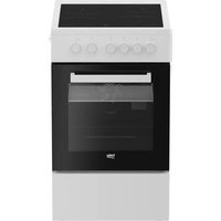
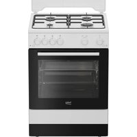
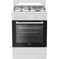
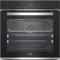
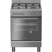
| Product Type | Built-in Hob |
| Brand | Beko |
| Model | BBUM12320XPE |
| Dimensions (W x D x H) | 590 x 520 x 45 mm (estimate) |
| Net Weight | Approximately 8 to 10 kg |
| Power Supply | 230 V / 400 V, 50 Hz, single-phase or three-phase depending on configuration |
| Maximum Power | Approximately 7.2 kW (estimate) |
| Cooking Type | Ceramic or induction depending on version (check the label) |
| Number of Burners | 4 (estimate) |
| Controls | Manual (touch or buttons) |
| Ventilation | Requires a 15 mm gap under the hob |
| Installation | Built into a worktop with a minimum thickness of 28 mm |
| Safety | Grounding mandatory, residual current circuit breaker protection recommended |
| Maintenance | Clean with a damp cloth and mild detergent, avoid abrasive products |
| Power Cable | Maximum length 2 m, cross-section according to technical specifications |
| Oven Compatibility | Can be installed above a Beko built-in oven |
| Warranty | Valid after proper installation by a professional |
Frequently Asked Questions - BBUM12320XPE BEKO
User questions about BBUM12320XPE BEKO
0 question about this device. Answer the ones you know or ask your own.
Ask a new question about this device
Download the instructions for your Other kitchen appliances in PDF format for free! Find your manual BBUM12320XPE - BEKO and take your electronic device back in hand. On this page are published all the documents necessary for the use of your device. BBUM12320XPE by BEKO.
USER MANUAL BBUM12320XPE BEKO
EN - Safety instructions
- Product must be installed by a qualified person in accordance with the regulations in force. The manufacturer shall not be held responsible for damages arising from procedures carried out by unauthorized persons which may also void the warranty.
- Preparation of location and electrical installation for the product is under customer's responsibility.
- The product must be installed in accordance with all local electrical regulations.
- Before installing the product, remove all the materials and documents in it and visually check if the product has any defects on it. If so, do not have it installed.
- Make sure that the user cannot reach the electrical connections after the installation.
- The product is heavy, carry the product with at least two people.
- The door and/or handle must not be used for lifting or moving the appliance. Use the lifting spaces on both sides of the product. Always wear protective gloves during transport and installation.
- Disconnect electrical connections in the area to be installed before installation.
- The surfaces of the furniture that the oven is to be installed in must be heat-resistant (100 °C minimum).
- Make sure that the furniture is in straight, horizontal position and that it is fixed before the installation of the appliance.
- Do not install heat insulation strips inside the interior of the furniture that the oven is to be installed in.
- The appliance must not be installed behind a decorative door in order to avoid overheating.
- The dimensions given in the installation diagrams are in mm.
Preparation of the furniture that the appliance shall be installed (Figures 2-3-4)
- The appliance is designed for installation into commercially available work tops. A safety distance shall be left between the appliance and the kitchen walls and furniture. (Figure 2-3)
-
The clearance where the appliance shall be placed on the worktop shall be cut as per the dimensions given figure 2-3.
-
If there is no hood on the appliance, allow a distance of 750mm from the hob surface to the furniture.
- If a shroud/hood is installed above the appliance, allow a distance for the installation height as described in the operating manual of the shroud/hood.
-** Minimum distance between the cabinets shall be equal to the width of the hob - In order to provide the necessary ventilation in the back of the kitchen furniture, openings should be created in the dimensions shown in figure 2.
- The electrical connection must be in the area A in figure 2 or outside the installation site.
Worktop thickness shall be at least 28mm (Figure 4a)
Ventilation
- Ventilation affects the heating performance of the appliance directly. Even if no problem is detected in the first inspections, customer concerns may occur due to the performance losses while cooking for longer periods when correct ventilation clearances are not provided.
- A minimum distance of 15mm shall be allowed between the lower surface of the hob and the upper wall of the oven (Figure 4b) to provide adequate ventilation. Additionally, a cross-section with the dimensions of 35× 500mm shall be left in the bottom of the furniture housing where the oven is placed. (Figure 2)
Installation of the appliance Connecting the appliance to the electricity supply
- Only connect the product to a grounded outlet/line with the voltage and protection as specified in the "Technical specifications". Have the grounding installation made by a qualified electrician while using the product with or without a transformer. Our company shall not be liable for any problems arising due to the product not being earthed in accordance with the local regulations.
- Before starting any work on the electrical installation, disconnect the product from the mains supply. There is the risk of electric shock!
- The product must be connected to the mains supply only by an authorised and
qualified person. The product's warranty period starts only after correct installation. Manufacturer shall not be held responsible for damages arising from procedures carried out by unauthorised persons.
- The appliance must be installed so that it can be completely disconnected from the mains supply. The separation must be provided by a switch built into the fixed electrical installation, according to construction regulations.
- The rear surface of the oven and the bottom surface of the hob get hot when it is in use. Make sure that the electrical connection does not come into contact with the rear surface otherwise, connections can get damaged.
- The connection cable must not be clamped, bent or trapped or come into contact with hot parts of the appliances. You may cause the appliances to short circuit and catch fire as a result of the cable melting. If the power cord is damaged, it must be replaced by a qualified electrician. Otherwise there is a risk of electric shock, short circuit or fire!
- The plug of the power cord should be easily accessible after installation (but not over the hobs).
- When wiring, you must comply with national / local electrical regulations and use socket outlet / line and plug suitable for the appliances. If the power limits of the product exceed the current carrying capacity of the plug and socket outlet / line, you must connect the product directly to the fixed electrical installation without using the plug and socket outlet / line.
- Make sure that fuse rating is compatible with the product.
- Connection must comply with national regulations.
- The mains supply data must correspond to the data specified on the type label of the products. You may see the hob's type label on the bottom of the hob and open the oven door to see the oven's type label.
- Power cable of your product must comply with the values in "Technical specifications" table.
- If the product will be connected directly to the supply power: If it is not possible to disconnect all poles in the supply power, a disconnection unit with at least 3
mm contact clearance (fuses, line safety switches, contactors) must be connected and all the poles of this disconnection unit must be adjacent to (not above) the product in accordance with IEE directives. Failure to obey this instruction may cause operational problems and invalidate the product warranty.
Additional protection by a residual current circuit breaker is recommended.
If the product is produced with cable:
- Connect the cord of product to supply power as identified below:
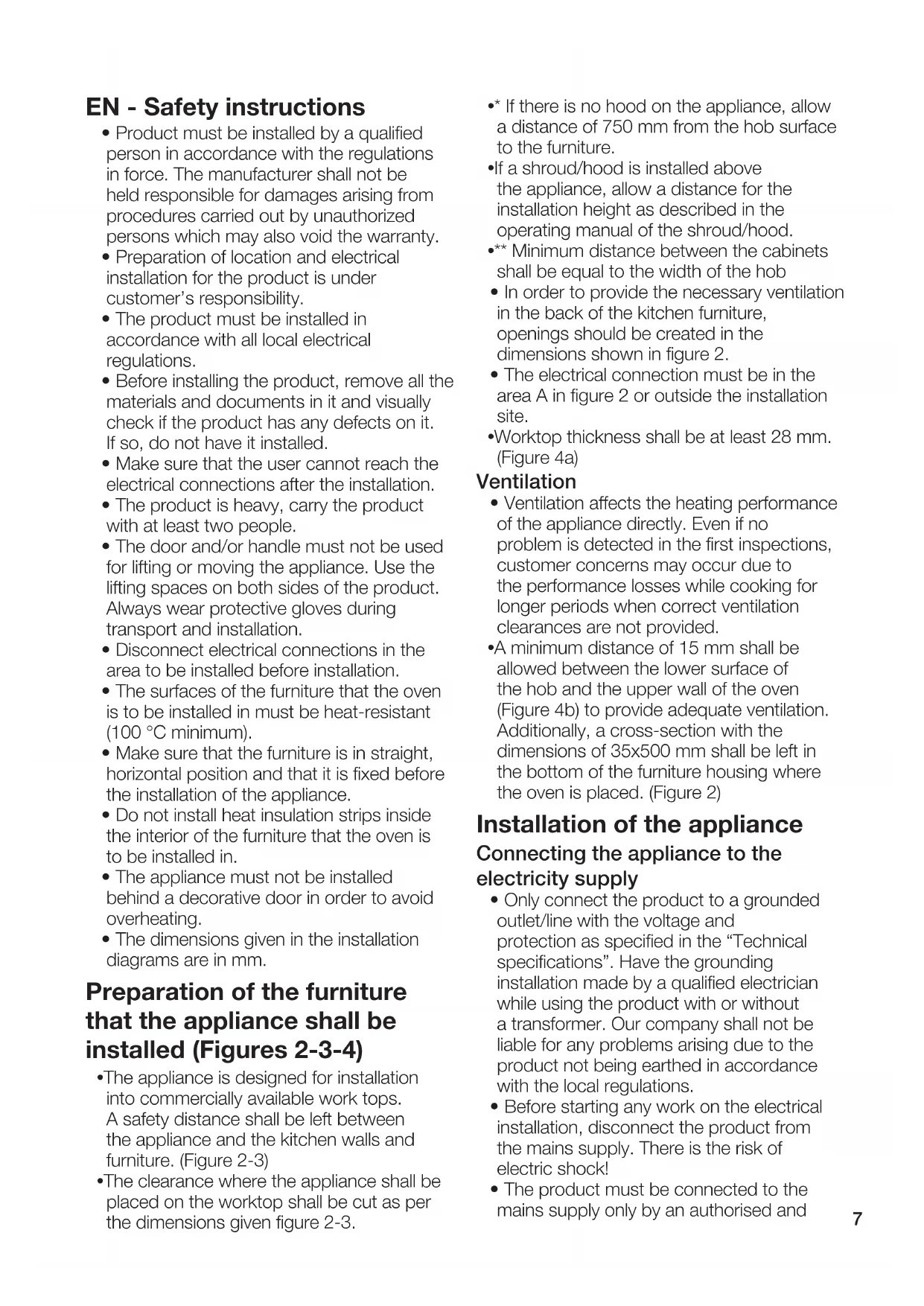
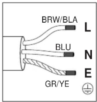
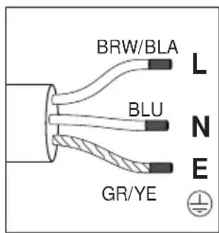
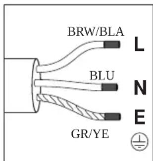
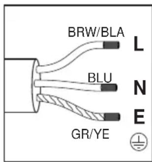
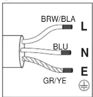
If your supply cord type is 3-conductor type, for 1-phase connection:
- (BRW/BLA) Brown/black = L (Phase)
- (BLU) Blue = N (Neutral)
- (GR/YE) Green/yellow wire = (E) (Earthing)
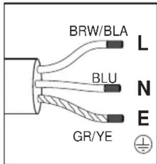
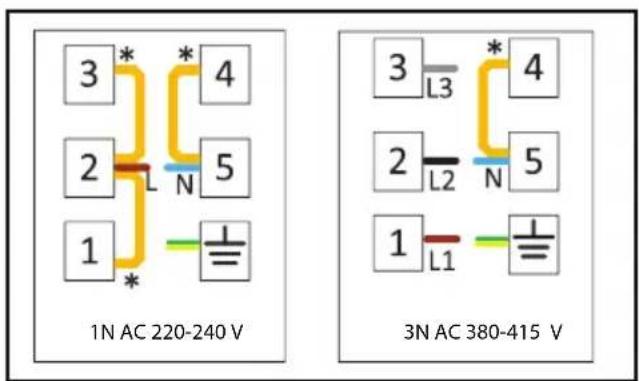
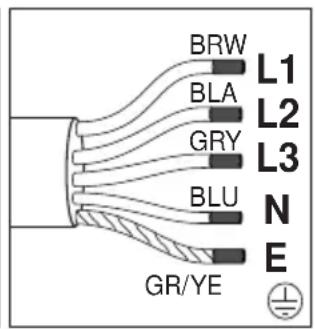
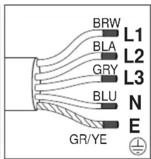
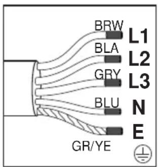
If your supply cord type is 5-conductor type, for 3-phase connection:
- (BRW) Brown = L1 (Phase)
- (BLA) Black = L2 (Phase)
- (GRE) Grey = L3 (Phase)
- (BLU) Blue = N (Neutral)
- (GR/YE) Green/yellow wire = (E) (Earthing)
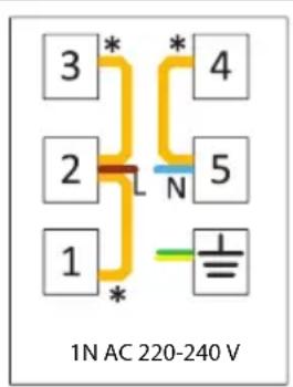
1 NAC 220-240 V
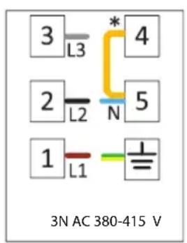
3 N AC 380-415 V
If the product is produced without cable:
A power cable that it is defined in the technical table home must be connected to product by following the instructions. Power cable must not be longer than 2m because of safety reasons.
- Open the terminal block cover with a screwdriver.
- Insert the power cable through the cable clamp below the terminal and secure it to the main body with the integrated screw on cable clamping component.
- Connect the cables according to the supplied diagram.
- Copper bridge
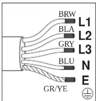
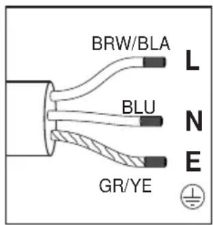
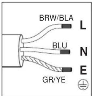
If your supply cord type is 3-conductor type, for 1-phase connection:
- Brown/black = L (Phase)
-Blue = N (Neutral) - Green/yellow wire = (E) (F arthing)
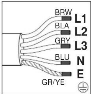
If your supply cord type is 5-conductor type, for 3-phase connection:
- Brown = L1 (Phase)
- Black = L2 (Phase)
-
Grey = L3 (Phase)
-Blue = N(Neutral) -
Green/yellow wire = (E) (Darthing)
-
After completing the wire connections, close the terminal block cover.
- Connect the power cable to supply power by routing it so that it will not contact the product and get squeezed between the product and the wall.
Prevention against possible fire risk!
- Ensure all electrical connections are secure and tight to prevent risk of arcing.
- Do not use damaged cables or extension cables.
- Ensure liquid or moisture is not accessible to the electrical connection point.
Placing and securing of the hob (Figures 5-6-7-8)
After preparing the installation location of the appliances, turn the hob upside down and place it on a flat surface.
- Affix the sealing gasket supplied with the appliance around the hob so that it shall be 1 - 2mm inside the outer edge of the glass as shown in Figure 5. Ensure that no clearance is left between both ends and between the glass and gasket.
- Screw and secure the mounting springs supplied with the appliance by engaging them to their seat on the lower housing of the hob as shown in Figure 6. (In some models, these springs may be secured to the appliance ex-factory.)
-
Turn the hob again and align it with the worktop and then place it on the worktop. Cooker shall be placed on the worktop thanks to the springs, and it shall be easily secured.
-
Ensure that the hob and the worktop are parallel when you place the cooker on the worktop. When it is not in parallel, connect the additional installation clamps supplied with the appliance as shown in Figure 8. Figure 8 shows the possible installation locations of the clamps. (The locations where the clamps can be attached may vary depending on the product model. You can connect according to the mounting holes on your hob.) Ensure the parallelism by attaching the clamps to the appropriate locations. The type and quantity of clamps supplied with the product may vary depending on the product model.
Making hob-oven connection and placing and fixing the oven (Figure 9a-9b-10)
- Connect the oven to the power supply.
- Slide the oven centered with at least two persons into the cabinet until half way.
- If your hob type is vitroceramic: The hob has a socket and a grounding cable to be connected to the oven. As shown in figure 9a, connect the socket to its slot on the oven in a way that the colors match. Fix the grounding cable with the screw shown in figure 9a.
- If your hob type is induction: The hob has two socket and a grounding cable to be connected to the oven. As shown in figure 9b, connect the sockets to its slot on the oven. Fix the grounding cable with the screw shown in figure 9b.
- Place the oven to the cabinet completely.
Fix the oven to the furniture using the screws provided. (Figure 10) - At the end of the installation, check that the screws are properly tightened and that the product is firmly fixed. If the oven is not installed in accordance with the instructions and the screws are not properly tightened, there is a risk of tipping during use.
Final check
- After installation, turn on the power supply.
- Read the user manual for the first use of the appliances.
- Check functions of appliances.
Removing the appliances
- Disconnect the appliances from the power supply.
- Unscrew the fastening screws of oven.v
- Pull out the oven with at least two persons from the cabinet until half way.
- Disconnect the oven and hob.
- Pull out the oven completely.
- If the hob is secured with additional clamps, unscrew the clamps first.
- Remove the hob by pushing upward from the bottom of the hob.
- (BRW) Braun = L1 (Phase)
- (BLA) Schwarz = L2 (Phase)
- (GRE) Grau = L3 (Phase)
- (BLU) Blau = N (Neutral)
- (GR/YE) Grüner/gelber Draht = (E) (Erdung)
- Kahverengi = L1 (Faz)
- Siyah = L2 (Faz)
- Gri = L3 (Faz)
- Mavi = N (Nötr)
- Yesil/sari kablo = (E) (Iopraklama)
Installation of apparatus
- (BRW/BLA) Brun/sort = L (Fase)
- (BLU) Blå = N (Neutral)
- (GR/YE) Grøn/gul ledning = (E)
(Jordforbindelse)
Hvis din netledningstype er 5-leder type, til 3-fasetilslutning:
- (BRW) Brun = L1 (Fase)
- (BLA) Sort = L2 (Fase)
- (GRA) Sort = L3 (Fase)
- (BLU) Blå = N (Neutral)
- (GR/YE) Gron/gul ledning = (E) (Jordforbindelse)
- (BRW/BLA) Marrón/negro = L (Fase)
- (BLU) Azul = N (Neutro)
- (GR/YE) Cable verde/amarillo = (E)
(Puesta a tierra)
- (BRW) Marrón = L1 (Fase)
- (BLA) Negro = L2 (Fase)
- (GRE) Gris = L3 (Fase)
- (BLU) Azul = N (Neutro)
- (GR/YE) Cable verde/amarillo = (E) (Puesta a tierra)
1 N AC 220-240 V

3 N AC 380-415 V
- (BRW) pruun = L1 (faas)
- (BLA) must = L2 (faas)
- (GRE) hall = L3 (faas)
- (BLU) sinine = N (null)
- (GR/YE) roheline/kollane juhe= (E) (maandus)
1 N AC 220-240 V
3 N AC 380-415 V
- (BRW)bruns = L1 (faze)
- (BLA) melns = L2 (faze)
- (GRE) pelëks = L3 (fāze)
- (BLU) zils = N (neiträls)
- (GR/YE) zala/dzeltena dzisla = (E) (zemejums)
1 N AC 220-240 V
3 NAC 380-415V
Ja izstradajums tiek ražots bez kabela:
- bruns/melns = L (faze)
- zis = N (neitrals)
- zala/dzeltena dzisla = (E) (Zemeyums)
- (BRW/BLA)kopnueBn/OpHn = L (pa3a)
- (BLU) cHHi = N (HeiTpapanb)
- (GR/YE) 3eJIeHn/JKOBtN npoBiD = (E) (3a3eMJIeHHra)
KIO Bn BnKOpNCToByeTe 5-KnIbHn IHyp XNBHeHH, dJa 3-0a3HOro nIKNHOeHH:
- (BRW)kopuHneBn = L1 (pa3a)
- (BLA)Чорнй = L2 (фаза)
- (GRE) cipni = L3 (φa3a)
- (BLU) cHHiN = N (HeiTpapb)
- (GR/YE) 3eJIeHn/JKOBtN npoBiD = (E) (3a3eMJIeHHa)
1 N AC 220-240 V

3 N AC 380-415 V
Ykuo Bnpi6 Bnpo6nctb8c8 6e3 ka6enl:
CnIOBn Ka6eJb, BN3NaueHn B TexHiyHni Ta6JIuCi, NOBHeH 6yTN PiIckIoUeHn Do Bnpo6y, DToTpIMyOuNCb IHCTpyKci.
CnIOBn Ka6eIb He NOBInHe 6yTu DOBWe 2 M 3 MipkyBaHb 6e3neKn.
- BiДкриTe кршky Клемнoro 6лOKу 3a ДОПOMOrOTO ВИКpyТК.
BCTaBTe cINOBn Ka6eIbYepe3 Ka6eJIbHn 3aTnCKaH NiD KInemy i PnIKpiniTb NOro Do OCHOBHO ROpNcy 3a DonOMOIO B6yDoBaHO rBnHTa Ha 3aTnCKaHi Ka6eIIO.
-Пдкючыka6и BiДповIDNodo cxemn.
MiHa nepemuKa
JaKUO Bn BVNKOpNCToBYeTe 3-KNJbHn WHyp XINBHeHHa, DnA OndHoFa3HOro NiKIOUeHHa:
- KOpNueBn/OpHn = L (Φa3a)
- cHnH = N (HeHTpaIb)
-3eJIeHn/JKOBtN npoBiD = (E) (3a3emIeHHra
KuO Bn BnKOpncToByeTe 5-KnJbHn ShHyp KInBneHH, dIa 3-0a3HO rPiKJIIOueHH:
-KopnueBn = L1 (Φa3a)
-чорн = L2 (фаза)
-cipni L3 (fa3a)
-cnH N(HeITpaB)
-3eJIeHn/JKOBtN npoBiD = (E) (3a3eMneHHa)
-Писязавершени3\' endання npobodIB 3akpiTe KpUkky KneMhoro 6noky.
-Пдкючы сиюь кабь дя поауЖИВЛЕнг,прКлавш ИОТ tak,цбВIH He KOHTaKtYBaB 3 ВиpoБOM i He 6yB3aTINCHyTN MIX BnPo6OM i CTiHO.
3anobiraHHaMOxJIbHm IOXeKHM pN3NKaM:
- IpepekoHaTecb, 0o Bci eJeKtpnHi 3'6dHaHHaHaiH Ta repMeTuHHi, 0o6 yHnKHyTN pN3NKy BnHnKHeHHa DyH.
He BnKOpncToBvIe noUkoJxHc Ka6eJI a6o noOBoKyBaqi.
3a6e3neuTe, uo6 piDnHa a6o B0nora He nOpTpanJn Do TOckn eNeKtpnHOro nnKluoyehn.
Po3miueHnTa 3akpinIeHnBapnilbHoI nobepxHi (pnc.5-6-7-8)
-Плд罗ТуВаВшmicе установкипсntpoIB,пepeВерhiTьВарильну NOBepxHIOДогорDNOMiNoCTaBTe IIHa pIBHy NOBepxHIO.
- PpHKpiiTy yuINbHOBaIbHy npOKnAdKy, ⅢO NOCTaHaTbC3 nPNCtPOEm, HABKOIO BapInbHOI NOBepxHi TaK, ⅢO6 BOHa 3HaxoDnIacr Ha BiDcTaHi 1-2 MM UcepeNHI 3OBHIshHbOro KpaIO CKla, kK Noka3aHo Ha pnc. 5. 3a6e3neUte, Ⅲo MIX O6OMa KINzAMn, a TAKOX MIX CKlOM i NpOKnAkoI Ho 3aIIINWBcR 3a3Op.
3aKpyTiB i 3aKpiniTb MOHTaXHi npyKHH,
IIO NOCTaAOTbCRA 3 pNcTPOEM,
3aKpINBnB IIX NocAOHOMy MiCi Ha
HNKHBOMy KOpNci BapInbHOI NOBepxHi,
rK NOKa3aHO Ha pnc.6. (DeaKi MoJeI
MOKyTB NOCTaHaTnCRA KOpNCtYBaCy
3 npNKpInIIeHIMn Do npcTpoH
npyKHHAM).
3HOBy nepeBepHiB BapnIbHy NOBepXHIO Ta BiDperyIIOte II NOLKeHHa BiHOCHO po6ooi Nobepxhi, a Notim yCTaHOBITb II Ha po6oii Nobepxhi. Heo6xIDHo, 0o6 PnIta 6yNa pO3MiueHa ha po6ooi NOBepxHi 3a DonOMOrO npyKIn I JERKO nIiDaBaJacr 3akpinJIeHHIO.
-Пд уас розиь варьнoi NOBepxhi Ha po6oii nobepxhi 3a6e3neueп napalenbHicTB po6ooi NOBepxHi Ta BapnIbHOIO nobepxHi.Яко HEMOJINBO DOcRHTN napaleJIbHocTi NOBepxOHb,prnkpiitbdoataKOBi MOHTaXHi 3aTnCKaHi,io nOCTaUaOTbcra 3 npictpoem,яNKoKa3aHoHa pnc.8. Ha pnc.8 BiO6paKeHi moKJIbBi Micza BCTaHOBLeHnHa 3aTnCKaHi. (Micya PO3TaUyBaHHa 3aTnCKaHi BMOKytB BiDpi3HЯTnca 3aJeXHo BiD MoDeJI BnPo6y.Ix MoKHa NiEEdHaTN BiINOBIDHO Do MOHTaXHHX OTBOpIB Ha BapnlbHi
noBepxhi.) 3a6e3neuTe napaneIbHicTb, npnKpinnBwN 3atncKai Do BIDNOBIDHNX Micu b po3TaWyBaHH. Tn i KINbKiCtB 3aTnCKaivB, IIO NOCTauaOTbcra 3 BInpo6om, MoKyTB BiDiPI3HrTnCra 3aJeKHO BiD MoJei BInpo6y.
BnkoHaHnpiD'EDHaHn mix BapNbHOIO NOBepxHeIo Ta dYXOBKOIO,po3MiueHnraTaΦikcaii dYXOBKn (pnc.9a-9b-10)
Пид' endaHte dYxOBky do eNeKtpoNocTaHaHHa.
BCTaBTe DyXOBky, CEHTpyIOuH, 3a DOonomoTOI npHaMHI DBOX Oci6 y waoSy Do NIOBOHN.
-
RaKuo Baw TnBapNbHoi nobepxhi c vitroceramic: BapnIbHa nobepxHЯ Mae po3'Em i Ka6eNb 3a3eMJeHHra, IIO NiIeHyOTbcra Do dYXOBKn. RaN oKa3aHo Ha pnc.9a, BCTaBte po3'em Do Noro OTBOpy Ha dYxOBci TaKIM YINHom, IIO6 KOJIbOpN 36irannc. 3aKpiniTb Ka6eNb 3a3eMJIeHHra TBnHTom, NOKa3aHIM Ha pnc. 9a.
-
Kaio Baw TnBapnIbHoi nobepxhi iHyKuiHH: BapnIbHa NOBepxHrae DaBra H13da Ta Ka6JIb 3a3emLeHHraKi cPiN PiKIIuOHTn Do dYxOBKn. RaK NOKa3aHO Ha MaIOHky 9b, NiKIIuOHTb PO3ETKn Do II OTBOPy Ha dYxOBci. 3akpinItb Ka6JIb 3a3emNeHHraBHTOM, NOKa3AHM Ha MaIOHky 9b.
BCTaTe dYxOBky y 7aΦy NOBHCtHO.
3aKpinitb DuyOBky Ha Me6nax 3a DonOMOrOHaHaAHx TBnHTiB. (pnc.10)
BkiHcMoHTaKy nepekoHaITeCb, 0rBnHTn npabNbHO 3ataryHi Ta BnPi6 HadiiHo 3aqikcoBaHO. KaO dYxOBky He BCTaHOBHeBOiIOBIDHO do IHCTpyKci, a RnHTn He 3aTAYHti HaJeXHM YHOM, icHyc He6e3neKa nepeKnDaHHn iD yac BnKOpNCtAHH.
OctaToUHa nepeBipka
- Picna BCTaHOBJIeHHy yBIMKHiTb eNeKTponoCTaayHH.
-Пердпршим ВИКОРиСТаHHЯmpnilaДВ npOHTaIte nociбнкОриСТуВачa. - PerpeBipTe yHkci npnaiB.
3HЯТТ npnlaIb
- BiD'eHaHTe npuJaB BiE eNeKtpomepeXi.
Bidkpytib 3akpiniouoyi rBNHTn BiD yXOBKn.v
BntarHItb DyXOBky 3a DonomoroI npHaMHI DBOX IIODee 3 WaoN Do noOBHH.
- Po3'eɪnHaɪTe ἀύχOBKY Ta BapɪnMbHy NOBepxHɪ.
BntarHItb dyxOBky nobHicTHo.
-ЯкwoBapnilbHa nobepxH3akpinneHa DOdaTkoBIMN 3aTnCKaayAM, CNoyATky BiDkpyTiB 3aTnCKaYi.
-3HIMITb BapnIbHy NOBepxHIO, HATNCHyBUn 3HN3y BapnIbHOI NOBepxHi BROPY.