HG 5000 E - Heat gun STEINEL - Free user manual and instructions
Find the device manual for free HG 5000 E STEINEL in PDF.

| Product type | Heat gun |
| Brand | Steinel |
| Model | HG 5000 E |
| Supply voltage | 230-240 V / 50 Hz |
| Nominal power | 3400 W |
| Temperature range | 25 °C to 600 °C (infinitely variable) |
| Display | Segmented LED (target and actual temperature) |
| Max. air flow rate | 800 l/min (infinitely variable) |
| Air pressure | 3000 Pa |
| Outlet tube diameter | 50 mm |
| Sound level | ≤ 70 dB(A) |
| Vibration level | ≤ 2.5 m/s² |
| Motor service life | Approximately 20,000 hours |
| Heating element service life | 500 to 800 hours |
| Mains cable length | 2.5 m (H07 RN-F 2×1.5) |
| Weight | 1190 g (without cable) |
| Dimensions (L × W × H) | 350 × 122 × 67 mm |
| Manufacturer warranty | 1 year |
| Motor type | Brushless, long service life |
| Settings | Progressive temperature and air flow, intelligent control |
| Heating element replacement | Easy, plugged with data chip |
| Mains cable replacement | Without opening the housing |
| Main applications | Thermoforming, plastic welding, paint stripping, heat shrink tubing, soldering, tinning, defrosting |
| Impact protection | Yes |
Frequently Asked Questions - HG 5000 E STEINEL
User questions about HG 5000 E STEINEL
0 question about this device. Answer the ones you know or ask your own.
Ask a new question about this device
Download the instructions for your Heat gun in PDF format for free! Find your manual HG 5000 E - STEINEL and take your electronic device back in hand. On this page are published all the documents necessary for the use of your device. HG 5000 E by STEINEL.
USER MANUAL HG 5000 E STEINEL
IE Socket Tool Company Ltd
Unit 714 Northwest Business Park
Kishane Drive · Balycoolin · Dublin 15
Tel.: 00353 1 8909120 · info@sockettool.ie
FR STEINEL FRANCE SAS
ACTICENTRE - CRT 2
Pue des Famards - Bât. M - Lot 3
FB-59818 Lesquin Cedex
Tél.: +33/3/20 30 34 00 - info@steinelfrance.com
NL Van Spijk B.V.
Postbus 2 - 5688 HP OIRSCHOT
De Schener 402-5688 HE OBSCHOT
Tel +31 498 571810
Tel: +34/93/772 28 49 - sea94@sea94.com
IT STEINEL Italia S.r.l
Largo Donegani 2 - IT-20121 Milano
Tel: +39/02/96457231
info@steinel.it · www.steinel.it
PT. F.Fonseca S.A.
Tel: +421/42/4 45 67 10
neco@neco.sk · www.neco.sk
RO Steinel Distribution SRL
505400 Basnov, jud. Brasov - Slr. Camcuui, nr.1
ESR Hala Scularie Bircurile 4-7
Tel.: +40101268 53 00 00 · www.stinel.ro
HR Daljinsko upravljanje d.o.o.
Bedricha Smetane 10 · HR-10000 Zagreb
t/0038513286877
daljinsko-upravljanje@inet.hr - www.daljinsko-upravljanje.hr
LV Ambergs SIA
Brivbas gative 195-16 - LV-1039 Riga
Tel.: 00871 67550740 · www.amborgs.lv
BG ТАШЕВ-ГАЛВИНГООД
B, 5/F, Wing Lok Street · Trade Centre
235 Wing Lok Street - Shaun Wan, Hong Kong
Tel: +852 2543 3440
info@fuslar.com.hk · www.fuslar.com.hk
STEINEL®
PROFESSIONAL
natural_image
Close-up of a metallic mechanical component with a cylindrical shaft and flange (no visible text or symbols)Information
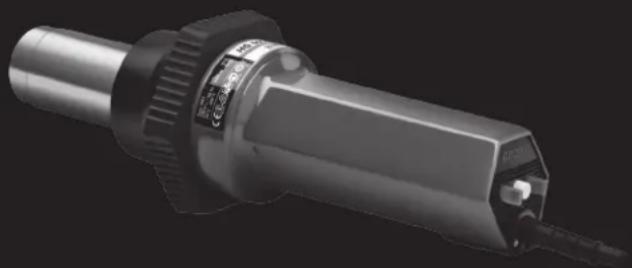
HG 5000 E

natural_image
Illustration of hands using a tool to adjust or install a pipe fitting (no text or symbols visible)
natural_image
Illustration of hands using a tool to adjust a mechanical component (no text or symbols present)natural_image
3D rendering of a white cylindrical pipe fitting with a small outlet (no text or symbols visible)Flachdüse
70×10mm
natural_image
3D rendered image of a metallic cylindrical object with a small protrusion at the bottom (no text or symbols visible)natural_image
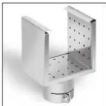
3D rendering of a metallic industrial component with perforated internal structure (no text or symbols)natural_image
Metallic mechanical component with curved and straight sections (no text or symbols visible)Klappreflektordüse
72 × 70 mm
natural_image
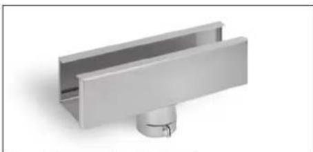
3D rendering of a metallic mechanical component with a cylindrical base and rectangular housing (no text or symbols visible)Schalenreflektordüse 250 x 45 mm
natural_image
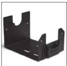
Black metal bracket component with mounting holes and cutouts (no text or symbols visible)HL Ablageständer
GB Translation of the original operating instructions

Safety precautions
Read and observe this information before using the tool. Failure to observe the operating instructions may result in the tool becoming a source of danger.
When using electric power tools, observe the following basic safety precautions to avoid electric shock as well as the risk of injury and fire. If the tool is not used carefully, it may cause a fire or injure persons. Check the tool for any damage (mains connection lead, housing etc.) before putting it into operation and do not use the tool if it is damaged. Do not leave the tool switched on unattended. Children should be supervised to make sure they do not play with the tool.
First time of use
A small quantity of smoke may develop when the tool is used for the first time. This smoke is caused by binding agents released from the heater's insulating film during the first time of use. To let the smoke escape quickly, the tool should be set down on its standing surface. The area you are working in should be well ventilated when using the tool for the first time. Any smoke coming out of the tool is not harmful!

Safety precautions
Take the ambient conditions into account.

refrigerators. Do not leave the tool unattended while in operation.
Do not expose electric power tools to rain. Do not use electric power tools when they are damp or in a damp or wet environment. Exercise care when using the tool in the proximity of flammable materials. Do not direct the tool at one and the same place for a prolonged period. Do not use in the presence of an explosive atmosphere. Heat may be conducted to flammable materials that are hidden from direct sight.
Store your tools in a safe place.

Protect yourself from electric shock.
Avoid coming into contact with grounded objects, such as pipes, radiators, cookers or

This tool may be used by children aged 8 or above and by persons with reduced physical, sensory or mental capabilities or lack of experience and knowledge if they are supervised or have been given instructions on how to use the tool safely and understand the hazards involved.
This tool may be used by children aged 8 or above and by persons with reduced physical, sensory or mental capabilities or lack of experience and knowledge if they are supervised or have been given instructions on how to use the tool safely and understand the hazards involved.

Safety precautions Safety precautions
Do not allow children to play with the tool. Children are not allowed to clean or carry out maintenance work on the tool without supervision.
Do not overload your tools.

Your work results and safety will be enhanced if you operate the tool within the specified output range. Do not carry the tool by the power cord. Do not unplug the tool by pulling on the power cord. Protect the power cord from heat, oil and sharp edges.
Beware of toxic gases and fire hazards.

Toxic gases may develop when working on plastics, paints, varnishes or
similar materials. Beware of fire and ignition hazards. For your own safety, only use accessories and attachments that are specified in the operating instructions or recommended or specified by the tool manufacturer. Using attachments or accessories other than those recommended in the operating instructions or catalogue may result in personal injury.
Repairs by a qualified electrician only

This electric power tool complies with the relevant safety regulations. Repairs should only be performed by a qualified electrician. Otherwise the user may run the risk of accidents.

Keep these safety pre- cautions with the tool.
Proper use
This electric power tool is intended for shaping and welding plastic, stripping paint as well as for heating heat-shrinkable tubing. It is also suitable for soldering
and tin-plating, undoing bonded joints and for thawing frozen water pipes.
Hot air tool specifications
■ Fully electronic temperature and airflow control
■ Airflow and temperature continuously variable
■ Intelligent motor and temperature control
■ Temperature display showing selected and actual temperature
■ Easy-to-change heating element
■ Brushless motor for long service life
■ Sturdy single-piece enclosure
■ Power cord can be changed without opening enclosure
System components
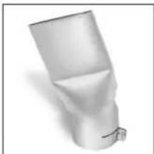
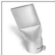
① Delivery nozzle ∅ 50 mm
② Heating element
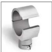
3 Knock guard
4 LED segment display
5 Temperature regulator
6 ON/OFF switch
7 Airflow regulator
Technical specifications
| Voltage 230-240 V / 50 Hz | |
| Output 3400 W | |
| Temperature 25-600°C, infinitely variable | |
| Display type LED segment display | |
| Airflow regulation infinitely variable | |
| Airflow rate max. 800 L/min. | |
| Air pressure 3000 Pa | |
| Delivery nozzle ∅ 50 mm | |
| Emission sound pressure level ≤ 70 dB (A) | |
| Total vibration value ≤ 2,5 m/s2 / K = 0,08 m/s2 | |
| Motor life approx. 20000 hrs. | |
| Heating element life approx. 500-800 hrs. | |
| Power cord H07 RN-F 2 × 1.5 | Length: 2.5 m |
| Weight (without power cord) 1190 g | |
| Dimensions 350 x 122 x 67 mm (at the knock guard ) | 3 |
Operation
Turn the tool ON at the ⑥ ON/OFF switch.
Preset the temperature 5 you require (25-600°C) at the temperature regulator. The temperature level as well as the letter "A" to show the setting mode are indicated on the LED segment display. Once the temperature has been preset, the tool automatically starts to show the actual temperature after approx. 3 seconds. The selected and actual temperatures are displayed in 10°C increments.
The airflow rate can be continuously varied at the airflow regulator 7. These regulations reflect the latest standards on mains pollution (EN 61000-3-3 Ficker standard, EN 61000-3-2 Harmonics standard).
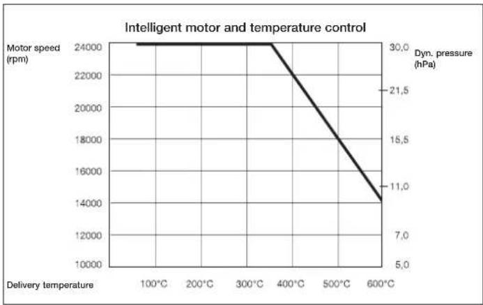
The tool has intelligent temperature and airflow control. This always gives priority to the temperature setting (see diagram).
Example: to reach the maximum temperature of 600°C while setting the motor speed to max. air delivery, the electronic system automatically reduces the airflow rate until 600°C is are reached. Accordingly, the airflow rate is increased again as soon as the temperature is lowered.
Intelligent motor and temperature control
line
| Delivery temperature | Motor speed (rpm) | Dyn. pressure (hPa) | | -------------------- | ----------------- | ------------------- | | 100°C | 24000 | 30.0 | | 200°C | 24000 | 30.0 | | 300°C | 24000 | 30.0 | | 400°C | 22000 | 21.5 | | 500°C | 18000 | 15.5 | | 600°C | 14000 | 11.0 |Changing the heating element
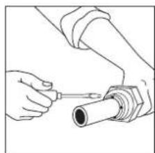
The plug-in heating element in the HG 5000 E can be changed in a matter of seconds. Every heating element contains
a chip with your specific data. On fitting a new heating element, its parameters are imported by the control electronics.
natural_image
Illustration of hands using a tool to adjust or install a cylindrical pipe (no text or symbols visible)
natural_image
Illustration of hands using a screwdriver to adjust a mechanical component (no text or symbols present)- Important! Disconnect tool from power supply.
- Undo four screws at the end of the delivery nozzle.
- Detach heating element and replace it with a new one.
- Firmly screw delivery nozzle back on again.
Changing the power cord
If the power cord is damaged, it can easily be
replaced without opening the enclosure.
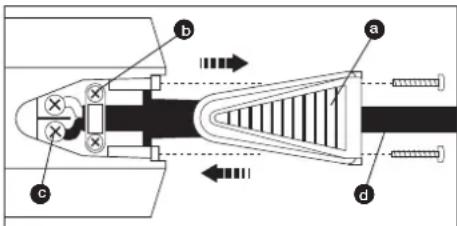
- Important! Disconnect tool from power supply.
- Undo screws and pull off ● cover cap.
- Release ● cable grip.
- Undo ● mains terminals.
- Pull out ● cable.
- Insert new cable and secure in reverse order (1. Firmly screw down mains terminals etc.).
Manufacturer's warranty
As purchaser, you are entitled to your statutory rights against the vendor. If these rights exist in your country, they are neither curtailed nor restricted by our Warranty Declaration. We guarantee that your STEINEL Professional sensor product will remain in perfect condition and proper working order for a period of 1 year. We guarantee that this product is free from material-, manufacturing- and design flaws. In addition, we guarantee that all electronic components and cables function in the proper manner and that all materials used and their surfaces are without defects.
Making Claims
If you wish to make a claim, please send your product complete and carriage paid with the original receipt of purchase, which must show the date of purchase and product designation, either to your retailer or contact us at STEINEL (UK) Limited, 25 Manasty Road, Axis Park,
Orton Southgate, Peterborough,
PE2 6UP, for a returns number. For this reason, we recommend that you keep your receipt of purchase in a safe place until the warranty period expires. STEINEL shall assume no liability for the costs or risks involved in returning a product.
For information on making claims under the terms of the warranty, please go to www.steinel-professional.de/garantie
If you have a warranty claim or would like to ask any question regarding your product, you are welcome to call us at any time on our Service Hotline 01733 366700.

Disposal
Electrical and electronic equipment, accessories and packaging must be recycled in an environmentally compatible manner.

Do not dispose of electrical and electronic equipment as domestic waste.
EU countries only:
Under the current European Directive on Waste Electrical and Electronic Equipment and its implementation in national law, electrical and electronic equipment no longer suitable for use must be collected separately and recycled in an environmentally compatible manner.
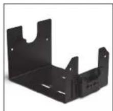
Accessories
Your retailer keeps a stock of these accessory nozzles.
natural_image
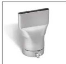
3D rendering of a white cylindrical pipe fitting with a flanged end and small protrusions (no text or symbols)Flat nozzle
70×10mm
EAN code: 4007841092719 Prod. No.: 092719
natural_image
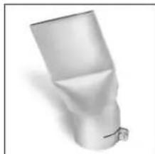
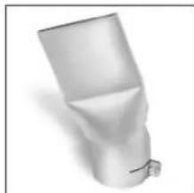
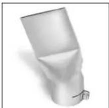
3D rendered image of a white plastic funnel-shaped object with a small protrusion at the bottom (no text or symbols)Flat angled nozzle 74 × 3 mm
EAN code: 4007841092818 Prod. no. 092818
natural_image
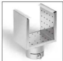
Metallic industrial component with perforated internal structure (no text or symbols visible)Sieve reflector nozzle 85 × 85 mm
EAN code: 4007841011901 Prod. no. 011901

natural_image
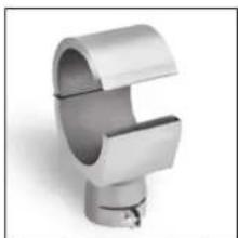
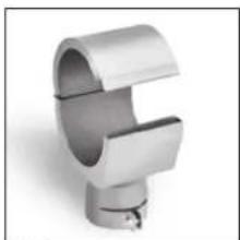
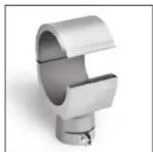
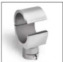
Metallic cylindrical pipe fitting with curved and straight ends (no text or symbols visible)Hinged reflector nozzle 72 × 70 mm
EAN code: 4007841011895 Prod. no. 011895
natural_image
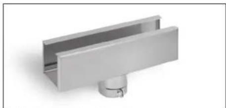
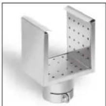
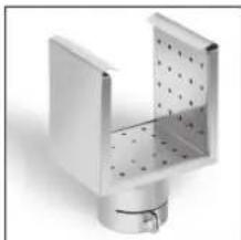
3D rendering of a metallic U-shaped metal bracket with a small circular base (no text or symbols)Shell reflector nozzle, 250 x 45 mm
EAN code: 4007841011918 Prod. no. 011918
natural_image
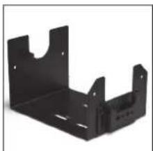
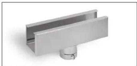
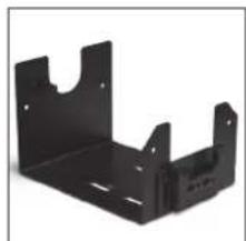
Black metal bracket component with mounting holes and slots (no text or symbols visible)Hot air tool stand
EAN code: 4007841034566 Prod. no. 034566
-20--21-
natural_image
Illustration of hands using a tool to adjust or install a cylindrical pipe (no text or symbols visible)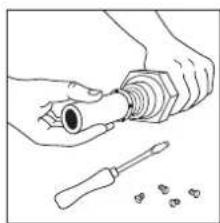
natural_image
Line drawing of hands using a tool to adjust a screwdriver with a screwdriver nearby (no text or symbols)natural_image
3D rendering of a metallic pipe fitting with a flanged end and small protrusions (no text or symbols)Buse plate de 70 x10 mm
natural_image
3D rendered image of a white plastic bottle-like object with a small protrusion at the bottom (no text or symbols visible)Buse plate coudée de 74 × 3 mm
natural_image
Metallic mechanical component with perforated internal structure (no text or symbols visible)natural_image
Metallic mechanical component with curved and straight sections (no text or symbols visible)natural_image
3D rendering of a metallic U-shaped metal bracket with a small circular base (no text or symbols)natural_image
Metal bracket component with mounting holes and cutouts (no text or symbols visible)Pied-support HL
natural_image
Illustration of hands using a tool to adjust or install a cylindrical component (no text or symbols visible)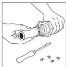
natural_image
Illustration of hands using a screwdriver to adjust a mechanical component (no text or symbols present)natural_image
3D rendering of a white plastic pipe fitting with a small outlet (no text or symbols visible)Vlak mondstuk 70 × 10 mm
EAN-code: 4007841092719 Art.nr.: 092719

natural_image
3D rendered image of a cylindrical object with a small protrusion at the bottom (no text or symbols visible)Vlak hoekmondstuk 74 × 3 mm
EAN-code: 4007841092818 ArLnr.: 092818

natural_image
3D rendering of a metallic mechanical component with internal perforations (no text or symbols)Zeefreflectormondstuk 85 × 85 mm
EAN-code: 4007841011901 Art.nr.: 011901
natural_image
Metallic mechanical component with curved and straight sections (no text or symbols visible)Klapreflectormondstuk 72 × 70 mm
EAN-code: 4007841011895 Art.nr.: 011895
natural_image
3D rendering of a metallic U-shaped mechanical component with a central cylindrical base (no text or symbols visible)Kokerreflectormondstuk 250 x 45 mm
EAN-code: 4007841011918 Art.nr.: 011918
natural_image
Black metal bracket component with mounting holes and a U-shaped cutout (no text or symbols visible)HL standaard
EAN-code: 4007841034566 Art.nr.: 034566
natural_image
Illustration of hands using a tool to adjust or install a cylindrical pipe fitting (no text or symbols visible)
natural_image
Line drawing of hands using a screwdriver to adjust a mechanical component (no text or symbols present)natural_image
3D rendering of a white cylindrical pipe fitting with a flanged end and small protrusions (no text or symbols)natural_image
3D rendered image of a white cylindrical object with a small protrusion at the bottom (no text or symbols visible)natural_image
Metallic mechanical component with perforated internal structure (no text or symbols visible)natural_image
Metallic mechanical component with curved and straight sections (no text or symbols visible)natural_image
3D rendering of a metallic mechanical component with a central hub and mounting base (no text or symbols visible)natural_image
Black metal bracket with mounting holes and a U-shaped cutout (no text or symbols)natural_image
Illustration of hands using a tool to adjust or install a pipe fitting (no text or symbols visible)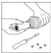
natural_image
Illustration of hands using a tool to adjust a component with screwdriver (no text or symbols)natural_image
3D rendering of a white cylindrical pipe fitting with a flanged top and side outlet (no text or symbols)Tobera plana 70 x 10 mm
Cód. EAN: 4007841092719 N° de art.: 092719

natural_image
3D rendered image of a cylindrical object with a small protrusion at the bottom (no text or symbols visible)Tobera plana angular 74 × 3 mm
Cód. EAN: 4007841092818 N° de art°: 092818
natural_image
3D rendering of a metallic mechanical component with internal cavities and perforated surfaces (no text or symbols)natural_image
Metallic mechanical component with curved and straight sections (no text or symbols visible)Tobera con reflector plegable 72 × 70 mm
Cód. EAN: 4007841011895 N° de art°: 011895

natural_image
3D rendering of a metallic mechanical component with a central hub and mounting base (no text or symbols visible)natural_image
Black metal bracket with cutouts and mounting holes (no text or symbols)Pie de reposo AC
Cód. EAN: 4007841034566 N° de art°: 034566
natural_image
Illustration of hands using a tool to adjust or install a cylindrical pipe fitting (no text or symbols visible)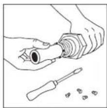
natural_image
Illustration of hands using a screwdriver to adjust a mechanical component (no text or symbols present)Byte av kabel
natural_image
3D rendering of a white cylindrical pipe fitting with a small outlet (no text or symbols visible)natural_image
3D rendered image of a cylindrical object with a small protrusion at the bottom (no text or symbols visible)Platt vinkelmunstycke 74x3 mm
EAN-kod: 4007841092818 Arl.-nr.: 092818

natural_image
3D rendering of a metallic mechanical component with perforated internal structure (no text or symbols)Perforerat reflektormun- stycke 85 × 85 mm
EAN-kod: 4007841011901 Art.-nr.: 011901
natural_image
Metallic mechanical component with curved and straight sections (no text or symbols visible)natural_image
3D rendering of a metallic mechanical component with a central hub and mounting base (no text or symbols visible)Skålformat reflektormunstycke 250 x 45 mm
EAN-kod: 4007841011918 Art.-nr.: 011918
natural_image
Black metal bracket component with mounting holes and a slot (no text or symbols visible)HL Förvaringsstativ
EAN-kod: 4007841034566 Art.-nr.: 034566
natural_image
Illustration of hands using a tool to adjust or install a pipe fitting (no text or symbols visible)
natural_image
Illustration of hands using a tool to adjust a mechanical component (no text or symbols present)natural_image
3D rendering of a white cylindrical pipe fitting with a flanged end and small protrusions (no text or symbols)Fladdyse 70 × 10 mm
EAN-kode: 4007841092719 Art.-nr.: 092719
natural_image
3D rendered image of a white plastic cylindrical object with a small protrusion at the bottom (no text or symbols visible)Vinkeldyse 74 × 3 mm
EAN-kode: 4007841092818 Art.-nr.: 092818
natural_image
Metallic industrial component with perforated interior and mounting base (no text or symbols visible)Si-reflektordyse 85 × 85 mm
EAN-kode: 4007841011901 Art.-nr.: 011901
natural_image
Metallic mechanical component with curved and straight sections (no text or symbols visible)Klapreflektordyse 72 × 70 mm
EAN-kode: 4007841011895 Art.-nr.: 011895
natural_image
3D rendering of a metallic mechanical component with a central hub and mounting base (no text or symbols visible)Skalreflektordyse 250 × 45 mm
EAN-kode: 4007841011918 Art.-nr.: 011918

natural_image
Black metal bracket with cutouts and mounting holes (no text or symbols visible)HL opbevaringsstativ
EAN-kode: 4007841034566 Art.-nr.: 034566
natural_image
Illustration of hands using a tool to adjust or install a cylindrical pipe fitting (no text or symbols visible)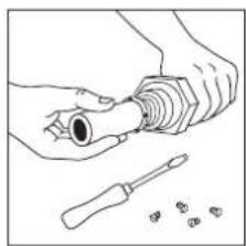
natural_image
Illustration of hands using a screwdriver to adjust a mechanical component (no text or symbols present)Johdon vaihtaminen
natural_image
3D rendering of a metallic pipe fitting with a flanged end and small base (no text or symbols)Tasosuutin
70×10mm
EAN-Code: 4007841092719 Tuolenro: 092719

natural_image
3D rendered image of a white cylindrical object with a small protrusion at the bottom (no text or symbols visible)natural_image
Metallic industrial component with perforated internal structure (no text or symbols visible)natural_image
Metallic mechanical component with curved and straight sections (no text or symbols visible)natural_image
3D rendering of a metallic mechanical component with a central hub and mounting base (no text or symbols visible)EAN-Code: 4007841011918
Tuotenro: 011918
natural_image
Black metal bracket with mounting holes and a small inset showing internal features (no text or symbols)HL-jalusta
EAN-Code: 4007841034566 Tuotenro: 034566
-82--83-
natural_image
Illustration of hands using a tool to adjust or install a pipe fitting (no text or symbols visible)
natural_image
Illustration of hands using a tool to adjust a mechanical component (no text or symbols present)natural_image
3D rendering of a white cylindrical pipe fitting with a flanged top and side outlet (no text or symbols)Flat dyse
70×10mm
EAN-kode: 4007841092719 Art.-nr.: 092719
natural_image
3D rendered image of a cylindrical object with a small protrusion at the bottom (no text or symbols visible)Flat vinkeldyse
74 × 3 mm
EAN-kode: 4007841092818 Art.-nr.: 092818
natural_image
3D rendering of a metallic industrial component with perforated internal structure (no text or symbols visible)Sil-reflektordyse
85 × 85 mm
EAN-kode: 4007841011901 Art.-nr.: 011901
natural_image
Metallic mechanical component with curved and straight sections (no text or symbols visible)natural_image
3D rendering of a metallic mechanical bracket with a cylindrical base (no text or symbols)Dyse med skålformet reflektor 250 x 45 mm
EAN-kode: 4007841011918 Art.-nr.: 011918

natural_image
Metal bracket component with mounting holes and cutouts (no text or symbols visible)HL støtte
EAN-kode: 4007841034566 Art.-nr.: 034566
natural_image
Illustration of hands using a tool to adjust or install a cylindrical component (no text or symbols visible)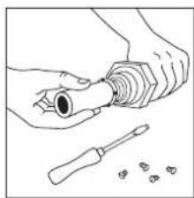
natural_image
Illustration of hands using a tool to adjust a screwdriver with a screwdriver nearby (no text or symbols)natural_image
3D rendering of a white plastic pipe fitting with a small valve (no text or symbols visible)Yassi meme 70 × 10 mm
EAN kodu: 4007841092719 Ür.-No.: 092719
natural_image
3D rendered image of a white cylindrical object with a small protrusion at the bottom (no text or symbols visible)natural_image
3D rendering of a metallic mechanical component with internal perforations (no text or symbols)natural_image
Metallic mechanical component with curved and straight sections (no text or symbols visible)natural_image
3D rendering of a metallic mechanical component with a central hub and mounting base (no text or symbols visible)natural_image
Metal bracket component with mounting holes and mounting holes (no text or symbols visible)HL Ayaklik
EAN kodu: 4007841034566 Ür.-No.: 034566
natural_image
Illustration of hands using a tool to adjust or install a cylindrical pipe fitting (no text or symbols visible)
natural_image
Line drawing of hands using a tool to adjust a mechanical component (no text or symbols present)1ROK GWARANCJI PRODUCENTA
Utylizacja
natural_image
3D rendering of a white plastic pipe fitting with a small outlet (no text or symbols visible)Dysza plaska 70 x 10 mm
Kod EAN: 4007841092719 Nr art.: 092719
natural_image
3D rendered image of a metallic cylindrical object with a small protrusion at the bottom (no text or symbols visible)natural_image
Metallic industrial component with perforated internal structure (no text or symbols visible)Dysza reflektorowa sitkowa 85 × 85 mm
Kod EAN: 4007841011901 Nr art.: 011901
natural_image
Metallic mechanical component with curved and straight sections (no text or symbols visible)natural_image
3D rendering of a metallic mechanical component with a central hub and mounting base (no text or symbols visible)natural_image
Black metal bracket with mounting holes and a U-shaped cutout (no text or symbols)Stojak HL
Kod EAN: 4007841034566 Nr art.: 034566
-108--109-
natural_image
Illustration of hands using a tool to adjust or install a pipe fitting (no text or symbols visible)
natural_image
Line drawing of hands using a screwdriver to adjust a mechanical component (no text or symbols present)электронику.
natural_image
3D rendering of a white plastic pipe fitting with a small outlet (no text or symbols visible)natural_image
3D rendered image of a cylindrical object with a protruding arm (no text or symbols visible)natural_image
3D rendering of a metallic mechanical component with perforated internal structure (no text or symbols)natural_image
Metal pipe fitting with curved and straight sections (no text or symbols visible)natural_image
3D rendering of a metallic mechanical bracket with a cylindrical base (no text or symbols)natural_image
Black metal bracket with mounting holes and a U-shaped cutout (no text or symbols)HL Подставка
IMPORTANT SAFETY INSTRUCTIONS READ THESE INSTRUCTIONS
WARNING: Read this instruction book before using. To reduce risk of fire or electric shock, do not expose to rain or moisture. Store indoors. When servicing, use only identical replacement parts. When using electronic tools, basic safety precautions should always be followed to reduce risk of fire, electric shock and personal injury. This hot air gun operates at 1100°F with no visual indication of temperature (no flame). Never leave device unattended. Otherwise risk of fire. The hot air stream at the outlet nozzle will bum flesh. Do not turn on hot air gun with hand in front of nozzle. DO NOT USE NEAR COMBUSTIBLE LIQUIDS. DO NOT USE FOR: • Heating gas engines • Heating car batteries • Thawing refrigerator equipment.
WARNING: Some dust created by power sanding, sawing, grinding, drilling and other construction activities contains chemicals known (to the State of California) to cause cancer, birth defects, or other reproductive harm. Some examples of these chemicals are: - lead from lead-based paints, - crystalline silica from bricks and cement and other masonry products, and - arsenic and chromium from chemically-treated lumber. Your risk from these exposures varies, depending on how often you do this type of work. To reduce your exposure to these chemicals: work in a well ventilated area, and work with approved safety equipment, such as those dust masks that are specially designed to filter out microscopic particles.
WARNING!
This tool is capable of producing temperatures up to 1100^ F of flameless heat at the nozzle. ALWAYS:
- Direct the heat away from yourself and others.
- Prevent ignition of combustible materials on or near the workpiece.
- Prevent blockage of intake and nozzle openings.
- Keep a fully charged fire extinguisher on hand.
- Allow the nozzle and accessory tips to cool to room temperature before storage.
Cautions
- WARNING: Hidden areas such as behind walls, ceilings, floors, soffit boards and other panels may contain flammable materials that could be ignited by the hot air gun when working in these locations. The ignition of these materials may not be readily apparent and could result in property damage and injury to persons. Do not use if in doubt about this hazard. When working in these locations, keep the hot air gun moving in a back-and-forth motion. Lingering or pausing in one spot could ignite the panel or the material behind it.
- This hot air gun can produce up to 1100^ F of flameless heat at the nozzle. Do not direct airstream at clothing, hair or other body parts. Do not use as a hair dryer.
- Do not use near flammable liquids or in an explosive environment (fumes, gases or dust). Remove materials or debris, that may become ignited, from work area.
- Always hold tool by plastic enclosure. The metal nozzle requires approximately 20 minutes to cool to where it can be touched. Do not touch nozzle or accessory tips until cool.
-
Do not store tool until nozzle has cooled to room temperature. Place tool in a clear area away from combustible materials while cooling.
-
Do not cut off air flow by placing nozzle too close to workpiece. Keep intake vents clean and clear of obstructions.
- Place tool on a level surface with the support rubber ring when tool is not hand held. Place cord in a position that won't cause tipping.
- Do not leave tool unattended while running or cooling down. Otherwise risk of fire.
- Keep a fully charged fire extinguisher nearby.
- Do not direct air flow directly on glass.
- Shield materials around the heated area to prevent damage or fire.
- Use only with 240 V AC voltage.
- Do not use in wet conditions.
- Not to be used by children. This is not a toy and should be respected.
- Do not use in bath or over water.
- Safety glasses should be worn when using this tool.
- It is recommended that leather gloves be worn when using a hot air gun.
- Always unplug after use.
- WARNING: Extreme care should be taken when stripping paint. The peelings, residue and vapors of paint may contain lead, which is poisonous. Any pre-1977 paint may contain lead and paint applied to homes prior to 1950 is likely to contain lead. Once deposited on surfaces, hand to mouth contact can result in the ingestion of lead. Exposure to even low levels of lead can cause irreversible brain and nervous system damage; young and unborn children are particularly vulnerable. Before beginning any paint removal process you should determine whether the paint you are removing contains lead. This can be done by your local health department or by a professional who uses a paint analyzer to check the lead contact of the paint to be removed. LEAD-BASED PAINT SHOULD ONLY BE REMOVED BY A PROFESSIONAL AND SHOULD NOT BE REMOVED USING A HOT AIR GUN.
Persons removing materials should follow these guidelines.
- Move the work piece outdoors. If this is not possible, keep the work area well ventilated. Open the windows and put an exhaust fan in one of them. Be sure the fan is moving the air from inside to outside.
- Remove or cover any carpets, rugs, furniture, clothing, cooking utensils and air ducts.
- Place drop cloths in the work area to catch any residue. Wear protective clothing such as extra work shirts, overalls and hats.
- Work in one room at a time. Furnishings should be removed or placed in the center of the room and covered. Work areas should be sealed off from the rest of the dwelling by sealing doorways with drop cloths.
- Children, pregnant or potentially pregnant women and nursing mothers should not be present in the work area until the work is done and all clean up is complete.
- Wear a dust respirator mask or a dual filter (dust and fume) respirator mask which has been approved by the Occupational Safety and Health Administration (OSHA), the National Institute of Safety and Health (NIOSH), or the United States Bureau of Mines. These masks and replaceable filters are readily available at major hardware stores. Be sure the mask fits. Beards and facial hair may keep masks from sealing properly. Change filters often. DISPOSABLE PAPER MASKS ARE NOT ADEQUATE.
- Use caution when operating the hot air gun. Keep the hot air gun moving as excessive heat will generate fumes which can be inhaled by the operator.
-
Keep food and drink out of the work area. Wash hands, arms and face and rinse mouth before eating or drinking. Do not smoke or chew gum or tobacco in the work area.
-
Clean up all removed residue and dust by wet mopping the floors. Use a wet cloth to clean all walls, sills and any other surface where residue or dust is clinging. DO NOT SWEEP, DRY DUST OR VACUUM. Use a high phosphate detergent or trisodium phosphate (TSP) to wash and mop areas.
-
At the end of each work session put the residue and debris in a double plastic bag, close it with tape or twist ties, and dispose of properly.
-
Remove protective clothing and work shoes in the work area to avoid carrying dust into the rest of the dwelling. Wash work clothes separately. Wipe shoes off with a wet rag that is then washed with the work clothes. Wash hair and body thoroughly with soap and water.
SAVE THESE INSTRUCTIONS
"This appliance has a polarized plug. To reduce the risk of electric shock, this plug is intended to fit in a polarized outlet only one way. If the plug does not fit fully in the outlet, reverse the plug. If it still does not fit, contact a qualified electrician. Do not modify the plug in any way."
You will find further operating instructions from p. 12
STEINEL America Inc.
9051 Lyndale Avenue South
USA - Bloomington, MN 55420
Tel: +1-952-888-5950
Fax: +1-952-888-5132
www.steinel.net

EU Declaration of Conformity
Declaration of Conformity with European Community Directives
Machinery Directive 2006/42/EC including amendments
DIN EN ISO 3744:2011-02, DIN EN 60745-1:2010-01, DIN EN ISO 11203:2010-01 DIN EN ISO 4871:2009-11, DIN EN 12096:1997-09
DIN EN 60335-1(VDE 0700-1):2010-11; EN 60335-1:2002 + A11 + A1 + A12 + A2 + A13 + A14:2010 DIN EN 60335-1/A15 (VDE 0700-1/A15):2012-03; EN 60335-1/A15:2011 DIN EN 60335-2-45(VDE 0760-45):2012-08; EN 60335-2-45:2002 + A1 + A2:2012 DIN EN 62233 (VDE 0700-366):2008-11; EN 62233:2008 DIN EN 62233 Ber.1 (VDE 0700-366 Ber.1):2009-04; EN 62233 Ber.1:2008
RoHS - Directive 2011/65/EU including amendments
Retention of documents and Archive:
(Geschäftsleitung / Chief Executive Officer)
Herzebrock-Clarholz 28/08/2017
Datum / Date