
HG 2320 E K - Heat gun STEINEL - Free user manual and instructions
Find the device manual for free HG 2320 E K STEINEL in PDF.
| Product type | Heat gun |
| Brand | Steinel |
| Model | HG 2320 E K |
| Power | 2000 W |
| Maximum temperature | 650 °C |
| Air flow | Adjustable (level 8) |
| Electronic temperature control | Yes, with program memory |
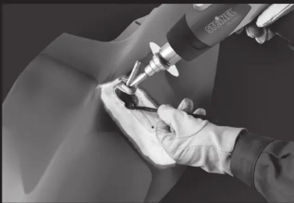
| Included accessories | 9 mm reduction nozzle, car repair nozzle, heat protection, Multi-Thermoflexx welding wire, stainless steel mesh |
| Use | Plastic welding, car repair |
| Safety | Heat protection, automatic shutdown |
| Weight | Approx. 800 g |
| Dimensions | Approx. 250 x 80 x 200 mm |
| Power supply | 230 V / 50 Hz |
| Maintenance and cleaning | Clean nozzles after use, avoid deposits |
| Spare parts and repairability | Parts available through after-sales service |
| General information | Compliant with European directives |
Frequently Asked Questions - HG 2320 E K STEINEL
User questions about HG 2320 E K STEINEL
0 question about this device. Answer the ones you know or ask your own.
Ask a new question about this device
Download the instructions for your Heat gun in PDF format for free! Find your manual HG 2320 E K - STEINEL and take your electronic device back in hand. On this page are published all the documents necessary for the use of your device. HG 2320 E K by STEINEL.
USER MANUAL HG 2320 E K STEINEL
- Manasty Road - Axis Park
Orion Southgate
CB-Peterborough Camba PE2 6UP
Tel.: +44/1733/366-700
steinel@steine.co.uk
IE Socket Tool Company Ltd
Unit 714 Northwest Business Park
Kilshene Drive - Balvocolin - Dublin 15
Tel: 003531 5809120
info@socialpolicy
FR STEINEL FRANCE SAS
ACTICENTRE - CRT 2
Tel: +4010/268 53 00 00
www.stenel.ro
HR Daljinsko upravljanje d.o.o.
Bedricha Smetane 10
HH-10000 Zagreb
v 00985 1 358 66 77
info@tashev-giving.com
www.tashev-gaiving.com
RU Инструмент
B, 5/F, Wing Lok Street
Tracel Centre
230 Wing Lok Street
Sheung Wan, Hong Kong
18: +652 2543 344
in@eluster.com.hk
代化进制版
STEINEL®
PROFESSIONAL
natural_image
Close-up of hands using a STENET tool to apply material to a small object (no visible text or symbols)Information
KFZ-Reparatur-Set
natural_image
Illustration of a hand holding a drill bit with a wire, no text or symbols presentnatural_image
Illustration of a tool applying material to a surface, showing a droplet and stick (no text or symbols)natural_image
Illustration of a hairdryer tool with a close-up view of its internal components (no text or symbols)natural_image
Hand holding a pair of scissors cutting a textured surface (no text or symbols visible)natural_image
Diagram showing a mechanical joint or bracket with dashed lines indicating motion or force direction (no text or symbols present)natural_image
Diagram showing a nozzle emitting particles from a container onto a surface, with no visible text or symbols.natural_image
Illustration of a hand using a power tool to lift a surface, showing no text or symbolsnatural_image
Mechanical assembly diagram showing a pin inserted into a base with arrows indicating direction (no text or symbols)natural_image
Mechanical sewing process diagram showing needle insertion and cutting tool (no text or symbols)natural_image
Mechanical assembly diagram showing a cylindrical component mounted on a base with a textured base (no text or symbols visible)natural_image
Diagram showing a curved surface with an arrow pointing to a small object, no text or symbols presentnatural_image
Diagram showing a mechanical component with an arrow indicating direction, no text or symbols presentnatural_image
Mechanical diagram showing a tool applying material to a workpiece on a workbench, with arrows indicating direction (no text or symbols present)natural_image
Diagram of a mechanical component with an arrow indicating rotation or movement (no text or symbols present)natural_image
Diagram showing a device with a downward arrow pointing to a surface, no text or symbols presentnatural_image
Illustration of a power tool applying material to a component (no text or symbols)natural_image
Illustration of a hand using a tool to apply material to a surface (no text or symbols visible)natural_image
Mechanical assembly diagram showing a tool inserted into a mounting bracket (no text or symbols visible)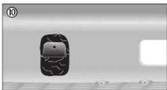
natural_image
Black and white image showing a damaged car with cracks on a grid floor, no visible text or symbolsEntsorgung
GB Plastic repair kit for motor vehicles
Dear Customer
| Thank you for purchasing the STEINEL plastic repair kit for motor vehicles. This brochure describes a new method of repairing motor vehicle plastics. From now on, the special |
welding rod and specially developed vehicle repair nozzle will make it easier and save time welding a whole host of plastic components.
What's different about this system?
| The special welding rod can be used on all thermoplastics. As a result, the painstaking process of finding out the type of plastic you want to work on now belongs to the past. |
bonds well with all thermoplastics. Thermoplastics can be worked and re-worked over long periods.
Important: the Multi-Thermoflexx welding rod must always be used in conjunction with the stainless steel wire mesh. It is highly flexible, extremely resistant to stress cracking and
Best results can only be achieved with the Multiflexx welding rod by using the vehicle repair nozzle (see "This is how it's done").
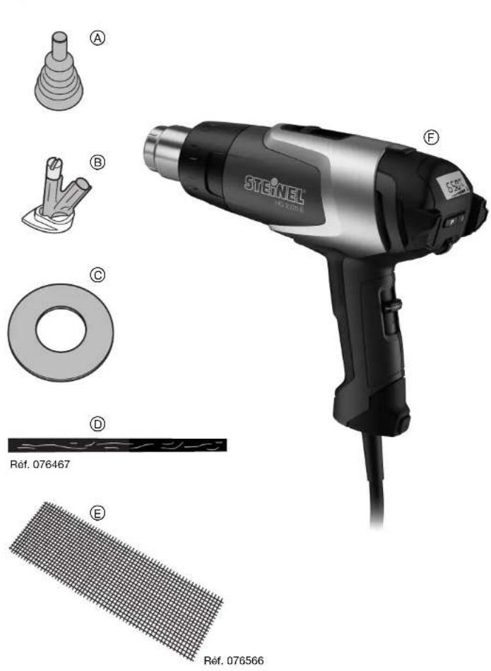
Contents
| AReduction nozzle, 9mm, Prod. No. 070601 |
| BVehicle repair nozzle |
①Stainless steel wire mesh, Prod. No. 076566
②HG 2320 LCD
©Temperature guard, Prod. No. 076665
①Multi-Thermoflexx welding rod, Prod. No. 076467

Additional safety notification
Not suitable for repairing:
- rubber parts
- pipes
- load-bearing parts
- film, foil or sheeting
Please note that when working on the motor vehicle, its fuel may increase the risk of explosion. Always observe the safety warnings in the operating instructions provided with the HG 2320 LCD.
Caution:
Unfamiliar plastics present a risk of fire and poisoning. Carry out a melting test on an inconspicuous spot to identify the thermoplastic material. Always ensure good ventilation while working. Do not inhale vapours.
For further details on the tool and its applications, please refer to the HG 2320 LCD operating instructions.
This is how it's done: Welding bumpers
Cracks with a length of up to 10 cm can be repaired without removing the bumper. If material has broken out of the bumper,
the damaged area should be repaired from both sides.
natural_image
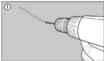
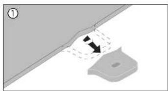
Illustration of a hand holding a drill bit with a wire, no text or symbols present①Drill a hole of approx. 5 mm in diameter at both ends of the crack to visually mark the crack ends and prevent further cracking.
natural_image
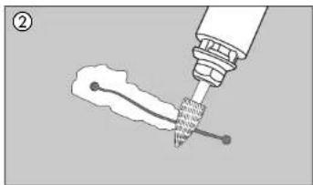
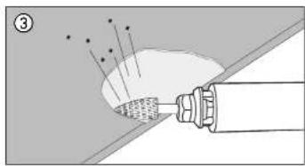
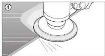
Illustration of a pipette dispensing liquid into a flame (no text or symbols)② Using an angle grinder/milling tool, remove approx. 1 mm of material over a width of approx. 20 mm on either side of the crack to insert the stainless-steel mesh later on. Using an orbital sander, now sand off the paint across a width of approx. 40 mm all the way round the crack.
natural_image
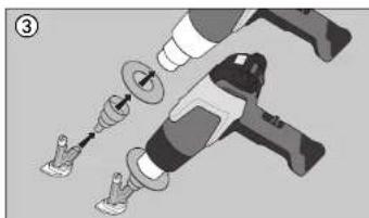
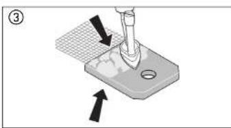
Illustration of a handheld electric drill with tool and screwdriver (no text or symbols)③Fit the heat guard, reduction nozzle and repair nozzle to the hot-air outlet nozzle. Set the hot air gun to 650 °C/air flow rate to speed 8 and save this setting to programme 4. The gun is ready for use after approx. 3 mins.
natural_image
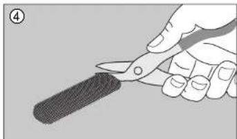
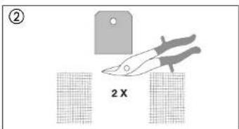
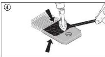
Hand holding a knife cutting a textured object (no text or symbols visible)④While the gun is warming up, cut the stainless-steel mesh to size. Dimension: 10 mm longer than the crack, extending by 20 mm beyond the crack on either side. Round off the corners.
Plastic repair kit for motor vehicles
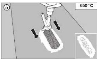
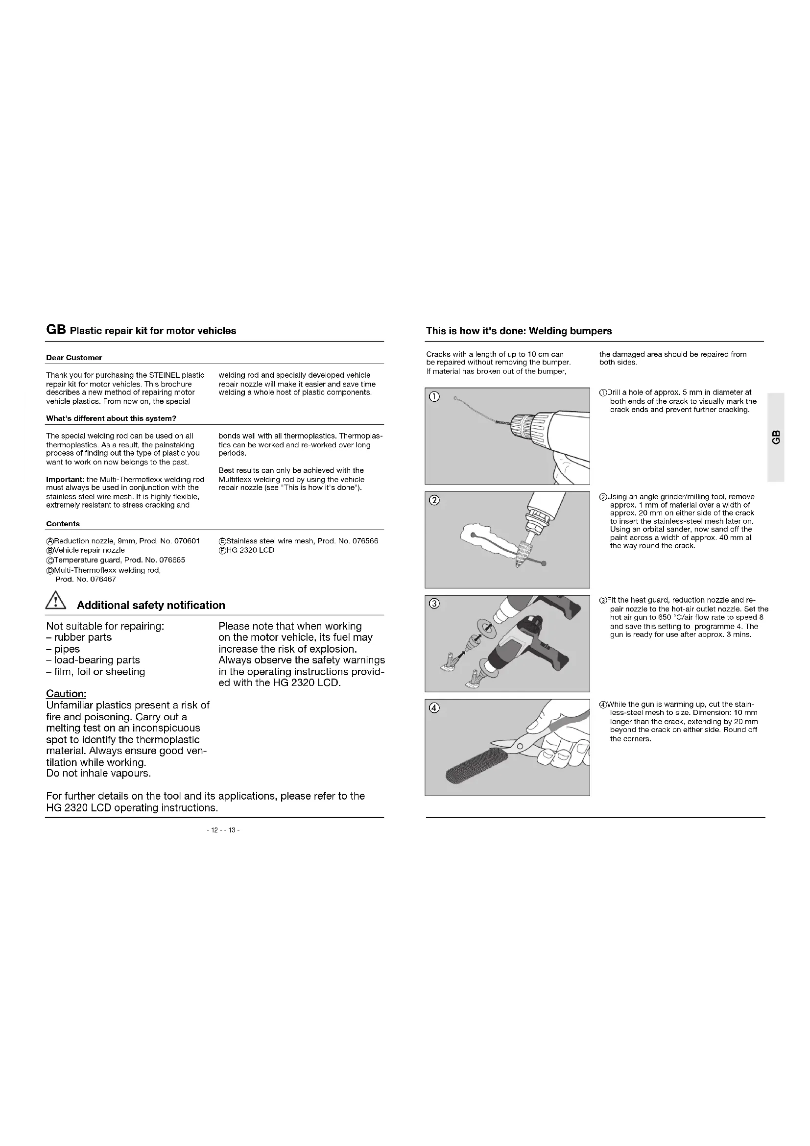
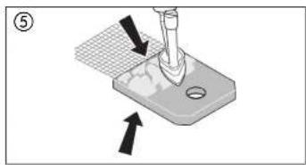
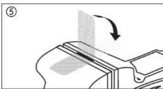
⑤Using the plastic repair nozzle, fuse the stainless-steel mesh into the plastic. First fix one corner, then heat the mesh all over and fuse evenly not applying too much pressure. For this process, always work in same direction. Note: The plastic must fully penetrate the mesh
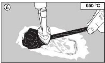
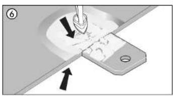
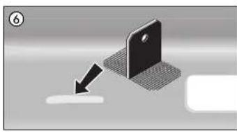
⑥Now carefully apply the Multi-Thermoflexx welding rod. Rod and surface must be evenly heated and completely fuse with the surface. The welding rod must turn ductile to produce a proper bond with the plastic material you are working on. Slowly and carefully smooth the material at the edges. Let the material cool down. Now create a surface for painting.
This is how it's done: Internal and external mounting tabs
natural_image
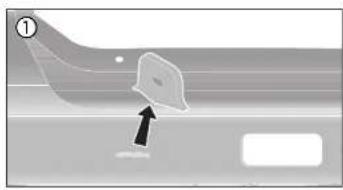
Diagram showing a mechanical component with dashed lines indicating motion or alignment, no text or symbols present①Repairing a detached bumper mounting tab.
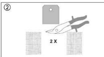
②Cut stainless-steel mesh to tab width for both sides of the mounting tab. 60 mm long, half-projecting.
natural_image
Diagram showing a pipe joint with a wire and particles, no text or symbols present③Procedure outside: From bumper and tab, remove approx. 1 mm of material in tab width
natural_image
Illustration of a hand cleaning a circular object with motion lines (no text or symbols)④Sand off paint approx. 30 – 40 mm around the area being repaired on bumper and tab.
natural_image
Mechanical diagram showing a tool pressing a component on a base, with arrows indicating motion direction (no text or symbols)⑤Using the plastic repair nozzle, fuse the stainless steel mesh into the plastic on the front side of the tab. Heat the mesh all over and fuse by applying even pressure. Note: The plastic must fully penetrate the mesh.
Plastic repair kit for motor vehicles
natural_image
Mechanical assembly diagram showing a tool pressing into a workpiece with arrows indicating motion direction (no text or symbols)⑥ Position the tab at the intended position and fuse the mesh into the bumper plastic using the vehicle repair nozzle.
natural_image
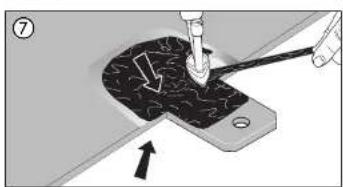
Mechanical assembly diagram showing a tool pressing down on a textured component (no text or symbols visible)⑦ Using the plastic repair nozzle, carefully apply the Multi-Thermoflexx welding rod. Rod and surface must be evenly heated and fully bond with the surface. Slowly smoothen the material at the edges.
natural_image
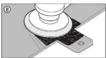
Mechanical assembly diagram showing a cylindrical component mounted on a base plate (no text or symbols visible)⑧Sand unevenness smooth on the outside and provide a surface suitable for painting.
Procedure inside:
Using the vehicle repair nozzle, fuse the mesh into the plastic of bumper and tab. Apply the Multi-Thermoflexx welding rod and carefully fuse with surface.
This is how it's done: Attaching a guide tab
natural_image
Diagram showing a curved object with an arrow pointing to a rectangular feature, no text or symbols present①Attaching a guide tab.
②Cut stainless-steel mesh to tab width for both sides of the tab. Length approx. 60 mm, half-projecting.
natural_image
Diagram showing a mechanical tool interacting with a surface, with arrows indicating direction (no text or symbols present)③On one side, fuse the stainless-steel mesh into the plastic. Heat the mesh all over and fuse by applying even pressure. Note: The plastic must fully penetrate the mesh.
natural_image
Illustration of a mechanical tool interacting with a workpiece on a base, showing force application and movement arrows (no text or symbols)④Using the plastic repair nozzle, carefully apply the Multi-Thermoflexx welding rod. Rod and surface must be evenly heated and completely bond with the surface. Slowly smoothen the material at the edges. Using the plastic repair nozzle, fuse the stainless steel mesh into the plastic on the rear of the tab. Now apply the Multi-Thermoflexx welding rod and carefully fuse with surface.
natural_image
Mechanical component diagram showing a curved surface with an arrow indicating rotation (no text or symbols)⑤Bend apart the projecting mesh at an angle of 90^ .
Plastic repair kit for motor vehicles
natural_image
Diagram showing a device with a screen and a drop arrow, no text or symbols present⑥ Position the tab at the intended position and fuse both sides into the bumper plastic using the vehicle repair nozzle. For better results at the tab base, the tab can be bent slightly towards the other side.
natural_image
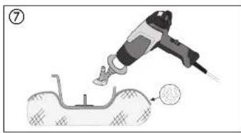
Illustration of a power tool applying material to a mechanical component (no text or symbols)⑦ TIP: With this method of tab attachment, it is recommended to place damp cloths or a cold jelly pad underneath to avoid deformation.
natural_image
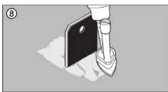
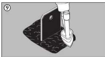
Illustration of a hand using a tool to apply material to a surface, with no visible text or symbols.⑧ - ⑩ Apply the Multi-Thermoflexx welding rod and slowly and carefully smoothen the material at the edges.
natural_image
Mechanical assembly diagram showing a tool inserted into a metal bracket (no text or symbols visible)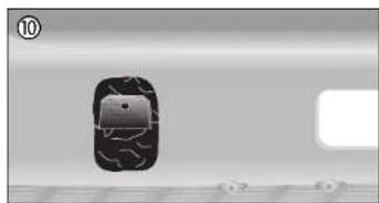
natural_image
Top-down view of a car with visible tracks and wheels, placed on a textured surface (no text or symbols)Disposal
Electrical and electronic equipment, accessories and packaging must be recycled in an environmentally compatible manner.

Do not dispose of electrical and electronic equipment as domestic waste.
EU countries only:
Under the current European Directive on Waste Electrical and Electronic Equipment and its implementation in national law, electrical and electronic equipment no longer suitable for use must be collected separately and recycled in an environmentally compatible manner.
natural_image
Illustration of a hand holding a drill bit with a wire, no text or symbols presentnatural_image
Illustration of a mechanical tool tiping a flame (no text or symbols present)natural_image
Illustration of a hand tool with multiple components and a base, no text or symbols presentnatural_image
Hand holding a pair of scissors cutting a textured object (no text or symbols visible)natural_image
Diagram showing a mechanical component with dashed lines indicating motion or alignment, no text or symbols presentnatural_image
Diagram showing a tool interacting with a surface, emitting particles (no text or symbols present)natural_image
Illustration of a hand using a power tool to press or spray a surface, with no visible text or symbols.natural_image
Mechanical diagram showing a tool pressing a component on a base plate, with arrows indicating motion direction (no text or symbols)natural_image
Mechanical assembly diagram showing a tool pressing into a workpiece with arrows indicating motion (no text or symbols)natural_image
Mechanical diagram showing a tool pressing a textured component onto a base plate (no text or symbols)natural_image
Mechanical assembly diagram showing a cylindrical component mounted on a base with a circular base and a small circular component attached (no text or symbols visible)natural_image
Diagram showing a curved object with an arrow pointing to a rectangular feature, no text or symbols presentnatural_image
Diagram showing a mechanical component with arrows indicating motion or force direction (no text or symbols)natural_image
Illustration of a tool applying material to a workpiece on a workbench, with arrows indicating direction (no text or symbols)natural_image
Diagram of a mechanical component with an arrow indicating rotation or movement (no text or symbols present)natural_image
3D illustration of a smartphone with a screen and a button, showing a downward arrow (no text or symbols)natural_image
Illustration of a power tool applying material to a mechanical component (no text or symbols)natural_image
Illustration of a hand using a tool to apply material to a surface, with no visible text or symbols.natural_image
Illustration of a mechanical component with a tool inserted, no visible text or symbols
natural_image
Top-down view of a car with visible tracks and wheels, set on a grid surface (no text or symbols)Élimination
natural_image
Illustration of a hand holding a drill bit with a wire, no text or symbols presentnatural_image
Illustration of a pipette dispensing liquid into a flame (no text or symbols)natural_image
Illustration of a hand tool and screwdriver assembly (no text or symbols)natural_image
Hand holding a pair of scissors cutting a textured object (no text or symbols visible)natural_image
Diagram showing a mechanical component with dashed lines indicating motion or alignment, no text or symbols presentnatural_image
Diagram showing a tool interacting with a surface, emitting particles (no text or symbols present)natural_image
Illustration of a hand using a power tool to clean or spray the surface (no text or symbols visible)natural_image
Mechanical diagram showing a tool pressing a component on a base plate, with arrows indicating motion direction (no text or symbols)natural_image
Mechanical assembly diagram showing a tool pressing into a workpiece with arrows indicating motion (no text or symbols)natural_image
Mechanical diagram showing a tool pressing down on a textured surface with an arrow indicating direction (no text or symbols)natural_image
Mechanical assembly diagram showing a cylindrical component mounted on a base with a separate plate and screw base (no text or symbols)natural_image
Diagram showing a curved object with an arrow pointing to a rectangular feature, no text or symbols presentnatural_image
Diagram showing a tool interacting with a surface, with arrows indicating direction (no text or symbols present)natural_image
Illustration of a mechanical tool interacting with a workpiece on a base, showing force application and movement arrows (no text or symbols)natural_image
Mechanical component diagram showing a curved section with an arrow indicating rotation (no text or symbols)natural_image
3D illustration of a smartphone with a screen and a button, showing a downward arrow (no text or symbols)natural_image
Illustration of a power tool applying material to a mechanical component (no text or symbols)natural_image
Illustration of a hand using a tool to apply material to a surface (no text or symbols visible)natural_image
Mechanical assembly diagram showing a tool inserted into a mounting bracket (no text or symbols visible)
natural_image
Close-up of a dark, irregularly shaped object with a circular dot on its surface, placed on a textured surface (no visible text or symbols)Smaltimento
natural_image
Illustration of a hand holding a drill bit with a wire, no text or symbols presentnatural_image
Illustration of a mechanical tool applying material to a flame (no text or symbols)natural_image
Illustration of a hair screwdriver with a tool and mechanical components (no text or symbols)natural_image
Hand holding a knife cutting a textured object (no text or symbols visible)natural_image
Diagram showing a mechanical component with dashed lines indicating motion or alignment, no text or symbols presentnatural_image
Diagram showing a pipe joint with arrows indicating flow or force direction (no text or symbols)natural_image
Close-up of a mechanical component with a base and lever, showing motion lines (no text or symbols)natural_image
Mechanical assembly diagram showing a turning tool interacting with a base plate (no text or symbols)natural_image
Mechanical assembly diagram showing a tool pressing into a component with arrows indicating direction (no text or symbols)natural_image
Mechanical diagram showing a tool pressing down on a textured surface with an arrow indicating direction (no text or symbols)natural_image
Mechanical assembly diagram showing a cylindrical component mounted on a base with a separate plate and screw base (no text or symbols)natural_image
Diagram showing a curved object with an arrow pointing to a rectangular feature, no text or symbols presentnatural_image
Diagram showing a mechanical component with an arrow indicating direction, no text or symbols presentnatural_image
Illustration of a mechanical tool applying material to a workpiece on a base, with arrows indicating direction (no text or symbols)natural_image
Mechanical component diagram showing a curved surface with an arrow indicating rotation (no text or symbols)natural_image
3D illustration of a smartphone with a screen and a button, showing a downward arrow (no text or symbols)natural_image
Illustration of a power tool applying material to a mechanical component (no text or symbols)natural_image
Illustration of a hand using a tool to apply material to a surface, with no visible text or symbols.natural_image
Mechanical assembly diagram showing a tool inserted into a mounting bracket (no text or symbols visible)
natural_image
Top-down view of a car with visible tracks and wheels, no text or symbols presentEliminación
natural_image
Illustration of a hand holding a drill bit with a wire, no text or symbols presentnatural_image
Illustration of a mechanical tool tiping a flame (no text or symbols present)natural_image
Illustration of a hand tool with multiple components, no text or symbols presentnatural_image
Hand holding a knife cutting a textured object (no text or symbols visible)natural_image
Diagram showing a mechanical component with dashed lines indicating motion or alignment, no text or symbols presentnatural_image
Diagram showing a tool interacting with a surface, emitting particles (no text or symbols present)natural_image
Illustration of a mechanical component with a base and pivot, showing motion lines (no text or symbols)natural_image
Diagram showing a mechanical component with arrows indicating force or movement, no text or symbols presentnatural_image
Mechanical assembly diagram showing a tool pressing into a component with arrows indicating motion (no text or symbols)natural_image
Mechanical assembly diagram showing a tool pressing down on a textured component (no text or symbols visible)natural_image
Mechanical assembly diagram showing a cylindrical component mounted on a base with a separate plate and screw base (no text or symbols)natural_image
Diagram showing a curved object with an arrow pointing to a rectangular feature, no text or symbols presentnatural_image
Diagram showing a tool interacting with a surface, with arrows indicating direction (no text or symbols present)natural_image
Illustration of a mechanical tool interacting with a workpiece on a workbench, showing force application and movement arrows (no text or symbols)natural_image
Diagram of a mechanical component with an arrow indicating rotation or movement (no text or symbols present)natural_image
Diagram showing a device with a magnified view and an arrow pointing to a small object (no text or symbols present)natural_image
Illustration of a power tool applying material to a surface with a magnified view (no text or symbols)natural_image
Illustration of a hand using a tool to apply material to a surface (no text or symbols visible)natural_image
Mechanical assembly diagram showing a tool inserted into a metal bracket (no text or symbols visible)
natural_image
Grayscale image of a damaged car with visible cracks and a grid floor, no text or symbols presentEliminação


- STEINEL®
- PROFESSIONAL
- Entsorgung
- GB Plastic repair kit for motor vehicles
- Additional safety notification
- Caution:
- This is how it's done: Welding bumpers
- Plastic repair kit for motor vehicles
- Procedure inside:
- This is how it's done: Attaching a guide tab
- Disposal
- EU countries only:
- Élimination
- Smaltimento
- Eliminación
- Eliminação
Brand : STEINEL
Model : HG 2320 E K
Category : Heat gun