
YT730895 - Multimeter Yato - Free user manual and instructions
Find the device manual for free YT730895 Yato in PDF.
| Product type | Digital multimeter |
| Brand | Yato |
| Model | YT730895 |
| Display | LCD 5 digits, 25000 counts |
| Sampling rate | 3 times per second |
| Power supply | 3 AA batteries (1.5 V each) |
| Dimensions | 180 × 90 × 50 mm |
| Weight (without batteries) | 260 g |
| Operating temperature | 0 to 40 °C, RH < 75% |
| Storage temperature | -10 to 50 °C, RH < 80% |
| Measurement functions | DC/AC voltage, DC/AC current, resistance, capacitance, frequency, duty cycle, temperature, diode test, continuity test, non-contact voltage detection (NCV), contact voltage detection |
| True RMS | Yes (for AC voltage and current) |
| DC voltage range | 25 mV to 1000 V |
| AC voltage range | 25 mV to 750 V |
| DC current range | 250 μA to 20 A |
| AC current range | 250 μA to 20 A |
| Resistance range | 250 Ω to 250 MΩ |
| Capacitance range | 9.999 nF to 99.99 mF |
| Frequency range | 250 Hz to 10 MHz |
| Temperature range | -20 to 1000 °C / -4 to 2000 °F |
| Special functions | Hold, Max/Min, Relative (REL), manual range selection (RANGE), backlight, auto power off (15 min) |
| Protection | Fast-blow fuse (replace with same type) |
| Maintenance and cleaning | Clean with a soft cloth, do not immerse, clean contacts with isopropyl alcohol |
| Included accessories | Test leads, thermocouple |
| Spare parts and repairability | Batteries and fuse replaceable by user |
Frequently Asked Questions - YT730895 Yato
User questions about YT730895 Yato
0 question about this device. Answer the ones you know or ask your own.
Ask a new question about this device
Download the instructions for your Multimeter in PDF format for free! Find your manual YT730895 - Yato and take your electronic device back in hand. On this page are published all the documents necessary for the use of your device. YT730895 by Yato.
USER MANUAL YT730895 Yato
This symbol indicates that waste electrical and electronic equipment (including batteries and storage cells) cannot be disposed of with other types of waste. Waste equipment should be collected and handed over separately to a collection point for recycling and recovery, in order to reduce the amount of waste and the use of natural resources. Uncontrolled release of hazardous components contained in electrical and electronic equipment may pose a risk to human health and have adverse effects for the environment. The household plays an important role in contributing to reuse and recovery, including recycling of waste equipment. For more information about the appropriate recycling methods, contact your local authority or retailer.
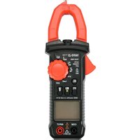
The multifunction meter is a digital measuring instrument designed to measure various electrical quantities.
Before using the meter, read the entire instruction manual and keep it for future reference.
The meter features a plastic housing, a liquid crystal display, and a measuring range switch. The housing has measurement jacks fitted. The meter comes with measurement cables terminated with plugs. The meter is sold without a battery.
ATTENTION! This meter is not a measuring instrument within the meaning of the Trade Metrology Act.
TECHNICAL DATA
Display: 5 digit LCD - maximum displayed result: 25000
Sampling frequency: 3 samples per second
Overload symbol: "OL" symbol displayed
Polarity symbol: “-” sign displayed before the measurement result
Battery: 3 × AA ; (3 × 1.5V)
Operating temperature: 0 to 40^ at relative air humidity < 75%
Storage temperature: -10^ ÷ +50^ at relative air humidity < 80%
Outer dimensions: 180 × 90 × 50 ~mm
Weight (without batteries): 260 g
ATTENTION! It is forbidden to measure electrical values exceeding the maximum measurement range of the meter.
| DC voltage AC voltage | |||||
| Range Resolution | tion Accuracy Range | Resolution Accuracy | |||
| 25.000 mV 0.001 mV | ±(0.05% + 3) | 25.000 mV 0.001 mV | ±(0.3% + 3) | ||
| 250.00 mV 0.01 | mV 250.00 mV 0.01 | mV | |||
| 2.5000 V 0.001 V | ±(0.05% + 3) | 2.5000 V 0.001 V | |||
| 25.000 V 0.001 | V 25.000 V 0.001 | ||||
| 250.00 V 0.01 | V 250.00 V 0.01 V | ||||
| 1000.0 V 0.1 V | 750.0 | V 0.1 V | |||
| Direct current + alternating current (DC) | Direct current + alternating current (AC) | ||||
| Range Resolution Accuracy Range Resolution Accuracy | |||||
| 2.5000 V 0.00 | 1 V | ±(0.5% + 3) | 2.500 V 0.00 | V | ±(1.0% + 3) |
| 25.000 V 0.00 | 1 V 25.00 V 0.01 V | ||||
| 250.00 V 0.01 | V | 250.0 | V 0.1 | V | |
| 1000.0 V 0.1 V | 750 V | 1 V | |||
| Direct current + alternating current (AC + DC) | ||
| Range | Resolution | Accuracy |
| 2.5000 V | 0.0001 V | ±(1.5% + 3) |
| 25.000 V 0.001 V | ||
| 250.00 V 0.01 V | ||
| 1000.0 V | 0.1 V | |
| Direct current | Alternating current | ||||
| Range Resolution | Accuray Range | Resolution Accuracy | |||
| 2.5000 A | 0.0001 A | ±(0.5% + 3)25.0mA | 2.5000 A | 0.0001 A | ±(0.8% + 3) |
| 20.000 A | 0.001 A | 20.000 A | 0.001 A | ||
| 25.000 mA 0.001 mA | 1 mA | 00 mA 0.001 mA | |||
| 250.00 mA 0.01 mA 250.00 mA 0.01 mA | mA 250.00 mA 0.01 mA | ||||
| 250.00 μA | 0.01 μA | 250.00 μA | 0.01 μA | ||
| 2500.0 μA | 0.1 μA | 2500.0 μA | 0.1 μA | ||
EN
| Resistance Capacitance | |||||
| Range Resolution Accuracy Range Resolution Accuracy | |||||
| 250.00 Ω 0.01 Ω ±(0.5% + 3) 9 | 999 nF 0.001 nF ±(5.0% + 20) | ||||
| 2.5000 kΩ 0.001 kΩ | 1 nF±(0.2% + 3) | 99.99 nF 0.01 | nF | ±(2.0% + 5) | |
| 25.000 kΩ 0.01 kΩ 999.9 nF 0.01 | |||||
| 250.00 kΩ 0.01 kΩ | 9.999 μF | 0.001 μF | |||
| 2.5000 MΩ 0.001 MΩ | ±(1.0% + 3) 99.99 μF 0.01 μF | ||||
| 25.00 MΩ 0.01 MΩ | |||||
| 250.0 MΩ 0.1 MΩ | ±(5.0% + 5) | 999.9 μF 0.1 μF | |||
| 9.999 mF | 0.001 mF | ±(5.0% + 5) | |||
| 99.99 mF 0.01 | mF ±(5.0% + 20) | ||||
| Frequency | ||
| Range | Resolution | Accuracy |
| 250.00 Hz 0.01 Hz | ±(0.1% + 2) | |
| 2.5000 KHz | 0.0001 KHz | |
| 25.000 KHz | 0.001 KHz | |
| 250.00 KHz | 0.01 KHz | |
| 2.5000 MHz | 0.0001 MHz | |
| 10.000 MHz | 0.001 MHz | |
| Duty cycle | ||
| Range | Resolution | Accuracy |
| 0.1% ÷ 99% | 0.1% ±(0.1% + 2) | |
| Temperature | ||
| Range | Resolution | Accuracy |
| -20°C to +1000°C | 1°C | ±(3% + 5) |
| -40°F ÷ +2000°F | 1°F | |
Accuracy: ± % of the indication ^+ weight of the least significant digit
ATTENTION! Before opening the instrument housing, disconnect the measurement cables and turn off the meter to avoid the risk of electrocution.
Safety instructions
Do not operate the meter in an atmosphere with excessive humidity or in the presence of toxic or flammable vapours, or in an explosive atmosphere. Before each use, check the condition of the meter and the measurement cables. In case of noticing any faults, do not start operation. Replace damaged cables with new ones, free from defects. If in doubt, contact the manufacturer. During measurement, hold the test leads only by the insulated sections. Do not touch the measurement points or unused jacks of the meter. Disconnect the measurement cables before changing the measured quantity. Never carry out maintenance work without ensuring that the test leads have been disconnected from the meter and that the meter itself has been turned off.
Replacing the battery
The multimeter requires batteries, the number and type of which are defined in the technical data section. It is recommended to use alkaline batteries. To install the batteries, open the instrument housing or the battery compartment cover on the underside of the meter. Before accessing the battery compartment, it may be necessary to remove the cover on the meter housing. Connect the battery according to its terminal marking, close the housing or battery compartment cover. If a battery symbol appears on the screen, the batteries must be replaced. To ensure measurement accuracy, it is recommended to replace the batteries as soon as possible, after the battery symbol appears.
Fuse replacement
The instrument uses a fast-acting safety fuse. In case of damage, replace the fuse with a new one with identical electrical parameters. To do this, remove the flexible housing cover, remove all screws fixing the
EN
two parts of the housing, open the meter housing and replace the fuse with a new one. The parameters of the fuse are indicated on the fuse housing. When replacing both fuses, it is recommended to replace the fuses one by one, so as not to change them with places.
Switching the meter on and off
Set the measurement switch to the OFF position to turn the meter off. The remaining switch positions activate the meter and make it possible to select the measurement quantity and its range. The meter will turn off automatically, if not in use. After about 15 minutes of inactivity, the meter will turn off automatically. This will reduce battery consumption. The user will be notified by a sound signal, approximately one minute before the power supply is turned off. If the meter turns off automatically, pressing the SEL button will restore the meter to operation.
SEL/REL button
Short press of the button will allow to select measurement quantity for settings of the main switch described using few quantities. Change the measurement quantity by pressing this button. Pressing and holding the button for approx. 2 seconds will activate the function that enables measuring the relative value. Activating the function during measurement will reset the display and record the value which was visible before displaying it as a reference level. The new measurement will show the difference between the measured value and the recorded reference value. When pressed again, the button restores the normal measurement mode. When the function is active, this is indicated by the REL symbol on the display.
RANGE button
The button is used to manually change the measuring range for a given quantity. When pressed, the AUTO symbol will disappear. Pressing the button again will switch the range in the order shown in the table. Holding down the button for approx. 1 second restores automatic ranging.
The MAX/MIN button
The button is used to activate the operating mode in which the maximum or minimum measurement result will be displayed from the moment of activating the given mode. Short presses of the button allow changing the measurement mode in a cycle: maximum (MAX) / minimum (MIN), while pressing and holding the button for approx. 2 seconds allows the instantaneous value (AUTO) to be activated. Symbols which will be displayed on the screen depending on the mode of operation selected are enclosed in brackets.
HOLD button*
The button is used to retain the measured value on the display. When pressed, the button will keep the currently displayed value on the display, even after the measurement is over. Press the button again to go back to the measurement mode. The operation of the function is indicated on the meter display with the "HOLD" message. Holding the button for approx. 2 seconds will activate the display illumination and LED light. Press the button again and hold it for approx. 2 seconds to turn off the display illumination and LED light.
Connecting the measurement cables
If the measurement cable plugs are capped, remove the caps before plugging the cables into the jacks. Connect the cables in accordance with the instructions provided in the manual. Next, remove the measuring section caps (if any) and proceed with the measurements.
Built-in buzzer
The meter has a built-in buzzer that emits a brief sound signal each time the selector is turned or a button is pressed to confirm the action has taken place. The buzzer will emit several sound signals per minute before the meter is automatically switched off and one long signal immediately before it is automatically switched off. The meter switches off automatically 15 minutes after the button has last been pressed or the selector's position has been changed.
MEASUREMENT PROCEDURE
Depending on the current position of the range switch, the display will show five digits. If the battery needs to be replaced, the multimeter indicates this by showing the battery symbol on the display. If the sign “-” appears on the display before the measured value, it means that the measured value has a reversed polarity relative to the meter's connection. If an overload symbol appears on the display, it means that the measurement range has been exceeded and it must be increased.
In the case of measurements of unknown values the meter should be set to the AUTO mode, in which case it determines the best measuring range by itself. If the selector is set to measure AC current or voltage, the meter will start measuring in the True RMS mode. This means that the true RMS value of the alternating wave will be measured. If a non-sine wave is measured, the actual RMS value for that particular wave will be displayed. Special care should be taken when measuring quantities within the
highest voltage range, in order to avoid electric shock.
ATTENTION! Never allow the measuring range of the meter to be smaller than the measured value. This can damage the meter and cause electrocution.
The correct connection of the cables:
The red cable goes in the jack marked VΩHz, mA μA or 20A.
The black cable goes in the jack marked COM.
Ensure the optimum measurement conditions in order to achieve the highest possible accuracy of measurement. The ambient working temperature should be in the range from 18 to 28^ and relative air humidity < 75% .
Example of accuracy determination
Accuracy: ± (% of the indication + weight of the least significant digit)
Measurement of DC voltage: 1.396 V
Accuracy: ±(0.8% + 5)
Calculation of error: 1.396 × 0.8% + 5 × 0.001 = 0.011168 + 0.005 = 0.016168
Measurement result: 1.396V± 0.016V
Voltage measurement
Connect the measurement cables to the VΩHz and COM jacks. Set the main switch to the voltage measurement position (V). Connect the measurement cables in parallel to an electrical circuit and read the voltage measurement result. The meter will automatically select the appropriate measuring range, which can be changed by pressing the RANGE button, if necessary. Never measure voltage that is higher than the maximum measurement range. This can damage the meter and cause electrocution. After selecting the lowest measurement range and when the measurement cables are disconnected, a changing measurement value can be seen on the display. It is a normal phenomenon. To eliminate it, it is enough to connect the tips of measurement cables with each other. While measuring the AC voltage, press the SEL button to measure the voltage frequency which will be displayed in the main row of the display.
Simultaneous measurement of DC and AC voltage
This mode is used to measure the voltage of signals where DC and AC components occur simultaneously, e.g. when measuring the noise of audio signals. Connect the measurement cables to the V Hz and COM jacks. Set the main switch to the voltage measurement position (V AC+DC). Connect the measurement cables in parallel to an electrical circuit and read the measurement result. The DC voltage measurement value is displayed in the main row of the display, while the AC voltage measurement value is displayed in the top row of the display. Press the SEL button briefly to read the result of the sum of the DC and AC voltage values (AC+DC).
Current intensity measurement
Depending on the expected current intensity value, connect the measurement cables to the mA A and COM jacks or to the 20A and COM jacks. Choose the appropriate measurement range using the selector. The maximum intensity of the measured current at the mA A jack can be 250mA . In the case of measuring current above 250mA , connect the cable to the jack marked 20A. The maximum intensity of current measured in the 20A jack may be 20A . The measuring time for currents higher than 2.5A should not exceed 15 seconds. After that, there must be a 3-5-minute break at a minimum before the next measurement. The mA A jack can be loaded with a maximum current of 250mA . It is absolutely forbidden to exceed the maximum values of current and voltage values for a given jack. The measurement cables should be connected in series to the tested electrical circuit. Select the type of current measured using the selector and read the measurement result. The meter will automatically select the appropriate measuring range, which can be changed by pressing the RANGE button, if necessary. While measuring the current, press the SEL button to measure the current frequency which will be displayed in the main row of the display.
Measurement of resistance
Connect the measurement cables to the VΩHz and COM jacks and set the range switch to the resistance measurement position marked with the symbol. Connect the test leads to the terminals of the measured component and read the measurement result. For measurements greater than 1M , the measurement may take a few seconds before the readout becomes stable, which is the normal response for high resistance measurements. Before applying the tips to the terminals of the measured component, an overload symbol is shown on the display. It is absolutely forbidden to measure the resistance of components through which electric current flows or of charged capacitors.
Diode test
Connect the measurement cables to the jacks marked VΩHz and COM and set the selector to the diode symbol. Now connect the test leads to the diode terminals, according to the direction of conduction and
EN
in the reverse direction. If the diode is working, it will show a voltage drop in its forward direction expressed in mV. If connected in the reverse direction, the display will show the overload symbol. Working diodes are characterised by a low resistance in the forward direction and a high resistance in the reverse direction. It is absolutely forbidden to test diodes through which electric current is flowing.
Conductivity test
Connect the measurement cables to the VΩHz and COM jacks. Set the selector to the buzzer symbol. Use the SEL button to select the conductivity test. This action will be confirmed by the display of the buzzer symbol. If the meter is used to measure conduction, the built-in buzzer will sound whenever the measured resistance drops below 50 Ω. The buzzer can also emit a sound when the resistance is in the range from 50 Ω to 100 Ω. It is absolutely forbidden to test conductivity in circuits through which electric current is fl owing.
Non-contact AC voltage detection
The meter has a sensor that can detect the electromagnetic field generated by AC voltage. Turning the selector to the position marked "NCV" will be confirmed by the display showing "EF". Bring closer the NCV sensor in the front plate of the meter to the point to be checked in terms of electromagnetic field presence. The greater the detected electromagnetic field, the faster the buzzer sound will be. This measurement can be used, for example, to detect hidden AC voltage wires. However, it should be remembered that such a measurement is affected by many external factors and may be disturbed by external electromagnetic fields. Do not rely solely on this method to detect live wires.
Contact voltage detection
Turn the selector to the "NCV" position. Connect the single cable to the VΩHz jack. Bring the test lead into contact with the component to be measured. If it is live, the buzzer will sound.
Capacitance measurement
Connect the measurement cables to the VΩHz and COM jacks and set the range switch to the capacitance measurement position. Make sure that the capacitor has been discharged, before the measurement. Never measure the capacitance of a charged capacitor as this can damage the meter and cause electric shock. When measuring high-capacitance capacitors, the measurement may take about 30 seconds before the result becomes stable.
When measuring small capacitances, subtract the capacitance of the meter and the measurement cables to obtain a more accurate result.
Frequency / duty cycle measurement
Connect the measurement cables to the VΩHz and COM jacks. Turn the selector to the position marked Hz %. Bring the test leads into contact with the component to be measured. The result of the frequency measurement is shown in the main row of the display and the result of the duty cycle measurement is shown in the top row of the display.
Temperature measurement
Connect the ends of the thermocouple leads to the INPUT and COM jacks. Set the meter selector to the ^ C ^ F position. Apply the metal part of the thermocouple to the tested surface. The measurement result given in degrees Celsius (°C marker) is shown in the main row of the display and the temperature measurement result given in degrees Fahrenheit ( ^ F marker) is shown in the top row of the display.
MAINTENANCE AND STORAGE
Wipe the meter with a soft cloth. Larger amounts of dirt should be removed with a slightly damp cloth. Do not immerse the meter in water or any other liquid. Do not use solvents, or corrosive or abrasive agents for cleaning. Care should be taken to keep the contacts of the meter and the measurement cables clean. Clean the contacts of the measurement cables with a cloth slightly soaked in isopropyl alcohol. In order to clean the contacts of the meter, turn off the meter and remove the batteries. Turn the meter over and shake it gently so that larger pieces of dirt fall out of the meter connectors. Lightly soak a cotton swab in isopropyl alcohol and clean each contact. Wait for the alcohol to evaporate and then install the batteries. The meter should be stored in a dry room, inside the supplied unit packaging.
GERÄTEBESCHREIBUNG
TEXHIHYXAPAKTEPNCTIKN
Ducnne:KK5uΦp-makcmaJIbHnpe3yIbTaT,ioBIO6paKyetbc:25000
YacToTa DnCKpeTn3aui: 3 pa3n Ha cekyHny
3nak nepebahtaxeHHa: biO6paKaetbcra cMBON
3NaK noJrphocTi: BiDobpaKaactbCnMBoN «-» IpepePe3yIbTaTOM BmipHOBaHH
Batarpe:3xAA; (3× 1,5~B)
Po6o7a Temnepatypa: 0÷ 40 rp.C; npu BiHochi Bonorocti < 75%
TemnepaTpya 36epirAHn: Bnue -10 rp. C ÷ +50 rp. C; npu BiHochi BOIorocti <80%
3OBHIuHi po3mipn: 180 x 90 x 50 MM
Bara (6e3 6atapeioK): 260 r
YB4A! 3a6opohrctb8nBMipOBaTH eektpuHl 3haueHH, 0ne nepeBnuyOTb MaKcImaHbHnn diana3OH BMIPOBaHb MyIbTmMetpa.
EKCJIYATAUcIyMULbTMETPA
YB4A! 3axncttnCe6e Bi ypaKeHH enektpuHm CtpyMOM, nepei BIKpTTM KOpTcy npntpo Bi edhaTe BumipobalbHi npoBOn i BmKHTb npuaad.
Ihcmpykuji 3 6e3neku
He BnKOpNCToByTe npIaB aTmocOpei 3 dyke BnCOKOBO BONORCTO TOKCNHMM a6o NERK03aMMNtMN napaM y Bn6yXoHe6e3neHNx yMObax. Ipepe KOKHM BnKOpNCaHHM nepeBipte cTaN MylbTMetpa i BmIPBOBaHbHX npOBdIB, kIIO NOMeHi 6yNb-RAI HecnpabHocTi, To He npCTyNaTE do p60TN. POnKOJKeHI npOBDo cIa3amHHTN HOBMn, 6e3 deEeKTIb. Y pa3i 6yNb-RAkNX cyMHIBiB, 6yNb Jnacka, 3B'jIKbc3 BnPO6hNKOM. IIqac BmIPBOHaHH TpMaIte BmIPBOAblHi npOBDo TIbKn 3a I3OJIbOBAHy qactHy. He TopKaItecraBzmaN Do BmIPBOAblHx TOOK A60 HEKBNAHIN H13D BmIPBOaHa. Ipeep 3MiHO BmIPBOHaOH BENuHH BiEeHnTE BmIPBOAblHi npOBDo. HikOnn He noNuHaTe po6OTn 3 TexHrHO OBCnyROyBaHH, He nepeKOHABuHc, 50 BmIPBOAblHi npOBDo 6yIn BIDcHAni Bid MybTMETpa, a Cam MybTbMeTp 6yB BmKHeHNI.
3amHa6amapei
MynbTmEpBnMaraeXINBHeHH BID 6aTapei, KINbKicb i TIN JNIX HabeHcI B TexHcHx DaHx. PeKoMeHyEcBnKOpNCBOyBaTN LyxHi 6aTapei. 106 BCTaHOBHTN 6aTapeIO, BiKpNIte KpnWky npnAdy aO KpnWky BicCkY 6aTapei, PO3TaOBoHcy Ha HNXHbOMy 6ozi MybTmEtpa. IOn OTPMaHnHa Doctny do 6aTapeHOrO BicCkY MoKe 3HaIObNTncr 3pyuHTN KpnWky KopNcy BmIPOBaay. NIKIOHt b 6atapeIO BIDNOBINO DO No3HaueHH KEm, 3akPnTE KopNyc aO KoNwky BicCkY. KaIO CBITNbCzMBON 6aTapei, ue O3Haue, 10 6aTapeIO CnID 3AmHHTN HOBO. INa 3aBe3neHHe rTOHocTi BmIPOBaHb peKoMeHyEcTBcRAKOMORA WBNDiue 3amHHTN 6aTapeIO nicra NOBn CmBOy 6aTapei.
3aMiHa 3anobixnHka
Pnncpi OchaueHn anapathm 3anobxHKOM 3 WBNKMMX xapaKTepnCTNkAMn. Y pa3i nooKpKeHHa 3amHtB 3anobixHK HOBm 3 iEHTNUHMn eNEKtpuHMM npametpaMn. IJra UBOrO 3HIMITb rHyUky KpnKy KopnyCy, BnKpyTtB BCI TBnHTn, IIO 3akpinIOKOpNcY, i BiKpnIe KopnyC JiuNbHKa, 3amHtB 3anobixHK Ha HOBn. NapamETpn 3anobixHKa HabeHn Ha KopnyCi 3anobixHKa. Ppr 3amiHi o6ox 3anobixHKIB peKomeHcyTbcra 3amiHOBaTN 3anobixHKnNo ODHMy, IO6 He 3amiHOBaTN IX MICyMn.
BeimKHeHHmaBumukAHMyIbumempa
YctaHOBka BmIPIOBAJIbHOrI IepEMNKaA B IIOJOKeHHR «OFF» BiKINOHITb MybTtMeTp. IHJi IIOJOKeHH RnepeMKAa aKTHyOHTb NOrO i Do3BOJRAOT Bn6paTN BeJIuHHy BmIPIOBaHH I Ioro dIana30h. MybTtMeTp Mac fYHKUIO ABOMATUHORo BiKNIQUeHHN B pa3I HeAKTUBHOCTI 3 6Oky KopNCtBuaya. Pp6n3HO uepe3 15 XBNIH 6e3dIAJIbHOCTI MybTtMeTp ABOMATUHO BIMKHeTcBc. Lc 3MeHNtB CNOXKBaHH 6bapei. Pp6n3HO 3a ONDy XBUNHy DO BIMKHEHH KINBEHH KOPNCtBuAH OTPMAE CNOBIeHHA 3a DOnOMTOO AKyCTNUHOrO CNHAny. KaIO MybTtMeTp BIMKHeTcBc ABOMATUHO, HATNCKAH KONKN SEL BiIDHOJIIOc PObOt MybTtMeTp.
Khonka SEL REL
Kopotke HATNCKAHH KHNKNO3BOJNC Bn6patn 3HaueHHBUMIPIOBAHHI npamaTePiB TOnOBHOro nepemHKaay, ONCAHnx DEkINbKOMA 3HaueHHM. 3MiHa po3Mipy BmIPIOBAHH 3diChioTbc 7xom HATNCKAHH LIEi KHONKn. Pn HATNCKAHHI Ta yTPMaHHi KONKn npOTraOM np6n3HO 2 ckyHd AKTNByEbCg FyHKqir, Ra DO3BOJNE BmIPIOBaTN BiHOCHy BEInuHy. YBIMKHHeHr FyHKii Nid cac BmIPIOBAHH np3BeDe I OCKDaHNR BIDobpaXeHHI npHRTB BiO6paXeHHR, BNIMTO nepH HIX MOxHa Byde 3HaueHH B JAKoCTI eTaONHoro pIBH. Hobn BmIP NOKae Pi3HnIO MIX BmIPRAHM 3HaueHHM i 36epeKeHm ONOpHM 3HaueHHM. NobTopHe HATNCKAHH KHNKn NOBepHTBCR B HopMaJIbHn peKIM BmIPy. IpTo Te, FyHKui AKTINBHA, CBiDnTHb No3HaUcKa REL Ha dncnnei.
Khoika RANGE
KhONka BnKOpNCbOyTbc Dn pyHoo 3MiHN dian a3oHy BmipobHHa 3aHoro po3Mpy. Iicna HatackaHH Ha dncne 3nKaCmBOn AUTO.HactynHe HataNcKaHH KhONKn nepemKae diana30n BiDnOBiHO DO nopRkky, 3a3NaueHoro B Ta6nui. YtpMaHH KhONKn npotraom np6n3Ho 1 ckyHn BiHOBIOc ABTomatuH N B6ip diana3oHy.
KhoIIka MAX/MIN
KhONKa BnKOpNCtOByeTbC4 nIg BkNIOUeHHpeXmMy po60Tu, npI yKOMy MaKcMmaBnH a6o MihimAbHnn pe3yNbTaBnMIpOBaHH 6yde BiOobpaKaTncs 3 MoMeHTy BkNIOUeHH daHOpeXmMy. KopOTki HATnCKaHH KhoKN Do3BOJnIObT b cIKNIuHO 3MiHOBaTH peXmBnMIpOBaHH: MaKcMym (MAX) / mHiymM (MIN), a HATnCKaHH Ta yTpMaHH KhoNK pOToTROM pnp6n3HO 2 CekHyDdo3BOJIe AKTNByaTH MNTTEBE 3NaueHHA (AUTO). CmBoH BIOobpaKaHObCBaB DyKKax, kI bdyTB BiOobpaKaTncs Ha ekpaHI B3aJIeKHOCTi BiO obpaHOro peXmMy po60Tu.
KhoNka HOLD*
KhONka BnKOpNCOTobyc Dnla 36epexeHHBumipHoro 3NaueHHa DaCnnei. Picna HATNCKAHHa KhONky BiO6paXac7bcra NotOHHe 3NaueHH, Ake 3aIIuNTbca Ha DaCnnei HabITb nicra BmIPOBAHHa. Uo6 nobepHyTncB pexHM BmIPBOAHHa, HATNCHTb KHONky ue pa3. Dja cyHKui Bkayetbcra Ha DaCnnei BmIPHOa 3Akom HOLD. YtpMaHHK hONki npotrrom np6n3Ho 2 cekyHd np3BeDe do niCbiYBaHH Ekpaha Ta CbitIOJHO rHIDKAtopa. NOBTOpHoo HATNCHTb i ytpMyTe KONky npotrorm np6n3Ho 2 cekyHd, Uo6 BmKHyTu ndCBHyBAHH eKpaha Ta CbitIOJHO IHINKaToP.
PiknueHH mecmoox npo0di8
KaBbhi wTeKePi OChaeni 3aIyWkAm, ix Heo6xIdHO 3HrTn nepei nd KIOyeHHm npOBODI do rH3d. PidKnIOHTb KaBen BiINOBIDHO Do Bka3IBOK, 0o MICTaTBcB IHCTpyKII. Notim 3HIMITb KPNKKBMMIPBOAbHoI qACTHN (Ka10e) i BIKOHaTE BMMIPBOAHN.
B6ydo8aHui 3ymep
Bmipohay mac B6yobahn 3ymep, kyn Bnae KopoTkn 3BykOBn CnHn np Koxhomy nepeiueHHI ceJIeKToPA a6o HATNCKAHHI KOXHOI KHONK B RKOCTI NIDTBepdxKeHHa TOrO, IIO HAtNCKaHH nPnHeCNo pe3yNbTaT. 3yme6 bye BNdaBAtn KInbKa 3BykOBnx CnHnIB XBNINHy, nepu HIX Bmipobay 6ye de ABTOMaTHNO BVKNIOeHN i ODNH DOBNI 3BykOBn CnHn NEpea ABtOMaTHN M BiKIOeHHM. Bmipobay ABtOMaTHNO BIDKnIOVAeTbcra Ype3 15 XBNINN nicra OCTaHHbOro HATNCKAHH KONKN A60 3MiHN NOLOXeHH CeJIeKToPA.
BNIKOHHHBIMIPIOBAHb
3aIeXHO bID nOToHOro nOIOKeHH NepemKaua dianao3oHy Ha dncnnei 6dybTi BINObpaKaTHc8 5uOp. Y pa3i Heo6xioHocTI 3amHn 6ataei, MybTmEtp iHOpMyE, BINObpaKaOH CNBON 6ataei Ha dncnnei. Ra3o Ha dncnnei BiObpaKaETCB CMBON «-» Ipeed BIMipRHM 3HaueHHM, Ce O3Haayac, 30 BmipRHe 3HaueHHMa e 3BOPOTy IOnpHiCTb 10do 3'EDHnra BmIPIOBaHa. Y pa3i, KOJI HA dncnnei 3'ABNtcbr Tlkbn CMBON nepeBaHTaxeHHn, ce O3Haayac NepeBnueHHn Dianao3oHy BmIPIOBaHH, B UboMy Bnnpky dianao3oh Bmipy NOBHeH 6Ty 3MIHeHn Ha 6IbW BUCOKn.
ДяВИМIPIOBAHb HeBIDOMORO 3HAeHHB BCTaHOITb MeTp B pexm «AUTO»,I06 BiH MIR Bu3HaHTn HauKpaun diana3OH BImipy.Якso ceNEKTOp HanaSTOBAHn Ha BIMipOBaHHCTpyMy a6o 3MiHoi Ha npYr, BIMIPOBaHNoH EBMIP BpeKmI True RMS. Ye O3Haac, Ioo BmipIOCTbCnPabXHc eEeKTHBHe 3HaueHHa 3MInHOi.Якso BmipIOBAHHIO NiJaTaBcra CnHaJI BIMipOBaHHa 3 HeCuHycoiDHOi XapakTePepNCtko1o, 6yde DaHo CnpabXHc eEeKTHBHe 3HaueHHa TAKORA CNrHany.Бydte OocJINBO ObepeKHi npN BIMIPOBaHHi Ha HauBnIoMy dianao3OH Hanpyr, 506 yHnKHyTu ypaxeHHa ENEKTPuHHM CTpyMOM.
YBATA! He donyckaite, 06 BmipobalbHn diana3OH MylbTMetpa 6yb MeHwe, HIX Bmipobahe 3naueHH. Ie Moxe npnbectn do 3HnueHHa MylbTMetpa i ypaxeHH eJektpnHIM CTpyMOM.
PpabnIbHe niiKNoeHH npoBodiB:
PpOBIy UepBOHOrO KOJIbOpY Do po3iEmy 3 no3HaueHHaM VΩHz, mA μA a6o 20A
UopHn Ka6eIb do rH3da 3 no3HaueHHaM COM
OToPMaMnMaKmMaJIbHO MoXJINBy ToOHicTB BIMipIOBaHHa, NOBHHi 6yTN 3a6e3neHcI ONTMaJIbHi yMOBn BmIPIOBaHHa. Tempeatypa HABKOJIuHbOro cepeOBuHa B diana3oHi BiD 18 rpaYcIB C do 28 rpaYcIB C i BdHocHI BONORCTI nobITpr<75%
PpuknaBuzhaueHHmouhocmi
ToHicTb: ± (% nOKa3aHH+ Bara HaimMeHs 3HaHooi UΦpU)
BmipobaHHn noctiHoi Hanpyr:1,396 B
Toohichtb: ±(0,8% + 5)
PozpaxyHOK norpiHocTi: 1,396 x 0,8% + 5 x 0,001 = 0,01168 + 0,005 = 0,016168
Pe3yIbTaT BmipKoBaHHa:1,396B±0,016B
BumipueaHaHa npyeu
Пдкнioчть ВIMIPOBaBHi Ka6eni Do po3'emib 3 no3haueHnM VΩHz i COM. BctaHObIb roNoBHn BmNKaH y noLoXeHHn BmIPOBaHHn Hanpyr (V). Пдкнioчть ВIMIPOBaBHi npobOdn napaleNo do eNeKtpuHoro NaHOra i nepeBipTe pe3ynbTaBmIPOBaHHn Hanpyr. BmIPOBaH aBTOMaTHNo nID6pe BiINOBiHN dianaoHn BmIPOBaHB, kNn npn Heo6xIdnoCTi MOxHa 3MiHTn, HATNCaOHn HA KHONky RANGE. HikoN He BmIPIOte HanpyrBuNSe MaKcImaNbHoro dianaoHy BmIPOBaHH. Lc MoKe npNBecTn DO 3HnueHH MyIbTMetpa I ypaXeHHeJeEKeTPuHHM CTpyMOM. NicJIy Bn6Opy HAnHHQTO dIana3OHy BmIPOBaHH Ta HeBikIOueHHx BmIPOBaBbHNx npOBdIB Ha DnCnEi MoKe BiObpaKaTncs3MiHHe 3NaueHH BmIPOBaHH. Lc HopMaJIbHe RaNSe, dIry Noro ycHeHHN DOCTaTHbO BKOPOTNTN KInci BmIPOBaBbHNx npOBdIB pa30M. Pd Yac BmIPOBaHH Happyr 3MHORO cTpMy HatNCHTb KHONky SEL, uO6 BmIPaTIu YactOtU Hanpyr, rka BiIObpaXaTbc B rONOBHom pydKy dinCnIIe.
OdHouache BumipioeaaHHaocmiuHO ma 3mHooHa npyu
LcBmipobAHn BnKOpncTOByeTcBdN BmipobAHn HAnpyr CnHaNIB, B kNX OJHOacHO npCyTHIOCTiHa i 3MiHn cKaIaObi, HanpNKaIa, npn BmipobAHHi yMIB ayioCnHaNIB. PkHIOHTb BmipobAblhi KaBen i do po3'EMiB 3 no3haueHHM VHz i COM. BctahOBiT roOBHN BmHKaY y nooXeHHBmipobAHn Hapyrn (VAC+DC).PiKIOHTb BmipobAblhi npoBoHn npaIeNBHO do eneKTPuHOro NaIzura i nepeBipTe pe3yIbTaB BmipobAHn. 3haueHHBmipobAHn noctiHoi Hanpyr (DC) BiO6paXaCTbcB a OCHOBOM pykDnCnIeR, TOni k3haueHHBmipobAHn 3MiHooHn Hapyrn (AC) BiO6paXaCTbcraY BepxHBompydKnIeR. Kopotko HaNTCHtB KhoNky SEL, o6 npouHtAn pe3yIbTaCMy 3HauehNocTIHoi Ta 3MiHNOHn Hapyrn (AC+DC).
BumipueaHHcmpymy
3aJexHo BID oukyBaHOro 3HaueHn BmipobaHO rtpmy nKIOCHy BmipobaBbHi npOBoHn do rhi3 da mA i COM a6o do rhi3da 20A i COM. Bn6epiB BiINOBHN diana3OH BmIPy 3a donOMoroo pyKn. MakcmaIbHn CTpym BmipobaHO rtpmy B rhi3di mA mAmOxte ctaHOHTN 250 mA npn BmipobHHCTpyMBy BNUE 250 MA, nIKIOUHTb KaEB Do rhi3da 3no3NaKoTO 20A. MakcmaIbHe 3naeHn BmipobaHO rtpmy B rhi3di 20 A moXe ctaHOHTN 20 A. Yac BmipobAHn CTPMy Bnue HIX 2,5 A He moXe nepeBnuYbAtn 15 cekHyd, nicra zuoro cnD 3poBtu nepepy He MeHwe 3-5 XBNHn pepeHn HAcTyNHM BmipobAHnAM. Hi3do mA mAmOxke 6tyn HabaHTaxKeHO MAKCMAIbHN CTPyMOM 250 MA. CyBopo 3abOpOHrTbcR nepeBnuYbATn MaCImaIbHI 3HaueHn CTPyMIB I Hanpy Dn DaHO rhi3da. BmipobaHn IpBOOni NobHHI 6tyn nIKIOUChE hi NocNiIOBHO Do BInpObyBAHOi ENEKTPuHNO NaHOrA, Bn6epiB dianazoh i Tn N BmipobaHO rtpmy 3a DonOMorIO nepeMnKaA i 3HTaIte pe3yIbTaBmipobAHn. BmipobAH uBTOMaTHO nIbePbe BInOBHN dianaoh BmipobAHb, knn npn Heo6XiHOCTMOHn 3MiHtN, HATNCKAQUHn HA KONKY RANGE. Pid Yac BmipobAHn HAnpyrN CTPMy HATNCHTb KHONk SEL, UoB BMIPaTn YactOTy HAnpyr, RaBIObpaxKaetbcB roNoBHOMy PAnKy DnCIIner.
BumipouhaHnOnIpy
ПдкнioчьВИМIPOBaBbHиKa6eni Do po3'EMiB 3 no3HaueHnM VΩHz Ta COM,пepeMHkaq diana3oHIB BCTaHOBt B NOIOxKeHHI BIMIPOBaHH onOpy - CmBOJ Ω. ПДКIOCHITb BIMIPOBaBbHi HAKOHeuHKn Do KIeM BIMIPOBaHO enEmeHTa i npOHTaIte pe3yIbTAT BIMIPOBaHH. ДЯ BIMIPOBaHHBAHnH, соpeBnUyToB 1 MΩ, BIMip MoKe 3aHrTa NkIbKa cekHyD Do TOrO, Ra pe3yIbTat cta6iN3yctbc, ce HopMaJIbHa peakui B pa3i BIMIPOBaHb BucOKnx onOpIB.пepe npKnaDAHm BIMIPOBaBbHnx HAKOHeuHKIBdo BIMIPOBaHO enEmeHTa, Ha DnCnIe 3'ABNTcR CmBOJ nepeBaHTaXeHHA. A6conHotHO 3abOpOHeNo BIMIPOBaTH onip enEmeHTIB, uee3 aki npOTiKa eNeKtpuHn CTpym a60 3apra- dxHnI KOHDcHcTopiB.
Tecm diode
PiikniohB Bmipobalni npoBoi ndo po3'emib 3 no3haeHHM VHz i COM, cJeKTop BCTaHObitb Ha CmBoni cblIOjOda. Bmipobalni HakoHeuHKn npNKlndtbo Do BNXODIaOa B HaprMky npOBIDHOcti b HaprMky 6nOKyBaHH. KaIO diO npauoe, To ha DiOJI, NiKIOHcHOMy B HaprMky npoxOJXHH, MN 6yDEmo 3HTyBatn naIHn HAnpyn Ha UcbOMy DiO, BpAxeH e MB. Y pa3i niKIOHcHn B 3BOPOTHOMy HApRMKy, Ha dncnii Byde BiO6paXATNC CMMBON nepeBaHTaxEHn. CnpABHI diOnx XapAKTePn3yOTBCn H3bkIM ONOpOM B HApRMky npOBIDHOcti i BnCOKM ONOpOM B HaprMky 6nOKyBaHH. A6coNIOTH 3aboponeHo TectyBatn diOIN, uee3 kpi npotikac enEeKtpuHn CTpym.
Tecm npoeiHocmi
IiikniuHtB Bmipobalbhi Ka6eni do po3'EMIB 3 no3haeHHM VΩHz i COM. BcTaHObit ceNeKTOp Ha 3y-Mep. 3a donomorio KhoNk SEL Bn6epitb Tect npoBIDHOCTI, 0o 6yde niTBePdKeHO CmBOJOM 3BykoBoro cHnAly. Pn BnKOpNCtAHHi BmipOBaay dJa BmIPOBaHHra npoBIDHOCTI 6ydoBaHNI 3ymep 6yde BKNHouATncs KOKHOrO pa3y, KOJI BmIPaHNI onip onyCTNTbcra HxKue 50 OM. Y diaana3OH biD 50 OM do 100 Om taKoX MoXHa NOuyTN 3ByKOBn CnHnA. A6conIOTHo 3abopoHeHO tectyBaTI npoBIDHICTb B IaHqorax, cheE3 kpi npotikac eNEKTPnuHNI CTpym.
Ee3koHmakmhe BureHennHaHpyeu 3miHnoo cmpyMy
Myltbmetp Ma eatnk, knn 3daTn BnBnTn enektpomarHIThe noJe, 0o rehepyctc 3miHHO HanpyroIO. NepemictiB ceneKTop B nonoXeHHN NCV, ue 6yde niTbepdxKeHO iHNkaTOpOM «EF» Ha dnCnneI. HabnxTe daTnK, no3haeHm NCV, po3taWobAHn Ha nepeHni naHeJI BMIpOBaay, do Micua, kye Heo6xio HO nepeBipuTN Ha HABHicTB enektpomarHIThoro noJr. Ym CnblHlwe BnBnHe enektpomarHITHE NOE, TUM WBNUe cnpaCbOBye 3ymep. Lc BmipOBaHH MoKHa BnKOpCTOByBaTu, HapNKlad, dnn BnBnEHH npNXoBAHx Ka6enib 3MiHHoro CTpyMy. Ondak nam'raTt, 0o Ha Take BmIPOBaHH BnIMBaec Barato 3OBHIwHix fakTopiB i BOHO MOnke npuyyBaTnc 3OBHIHIMn enekTpOMaHTHMNI NOJAMN. He NOKndaaiTeCBAkNIOUHO Ha cei MeToD IINBnBleHH NPOBoID iNd HAnpyTOIO.
KohmkmHe eueeHnHa npyu
NoBepHtB ceneKTopHn nepeMnKauy y nooKeHHN NCV, nkiKIOuHTb oINn Ka6eIb do po3'emy VΩHz. PnueiTb BmipIOBaHn HakoHeHHK B KOHTaKT 3 BmIPIOBaHm KOMNOHEhTom, RkUO BiH 3HaXoDntb- Cn iN HanpyroIO, 3Mep BnDaCTb 3ByKObN CnHaJ.
Bumipobanha emHocmi
IiiknHtB BmipOBaBbHi dpotn do po3'emib 3 no3haeHHM VHz i COM, nepemkaay dianazohIB BCTaHOBIT B NOIOXeHHI BmipOBaHHr ONopy. Pepe BmipOBaHHM nepeKoHaItecra, 00 KOHeCAtop pO3pAIXeHN. HikoJn He BmipHOte cMHicTB 3apJxKeHOro KOHeHCaTopa, ce Moze NowKOaHTB BmipOBaU i npn3BeCt Do ypaXeHH eJeKtpuHm CTPyMOM. Ppi Bmipi EMHOCTi KOHeHCaTOpB
UA
3 BeHIO EMHICIO, BIMIPHOBAHHaMOKe 3aHHTN 6n3bKO 30 ckyH, nepH HIX pe3yIbTaT cta6iJIy-CTbC.
Y pa3i BmipioBaHH HeBeJINKHX EMHOCTeI, nIa OTpMaHH 6JIbI TOOHOr pe3yIbTaTy, Heo6XiHIO BIDHRTN EMHCtB IInJbHNka i BmipioBaJIbHX Ka6JIIB.
BumipueaHHa yacmou / koepiuichma 3anaeHnna
IiKnKIOHtB BmipOBaBbHI Ka6eni Do po3'EMIB 3 no3haeHHM VΩHz i COM. BCTAHOBiB ceneKTOp y noJIOXeHH, no3haeHe CNMBONOM Hz %, PnPBEdITb BmipOBaBbHI HAKOHeHHKN B KOHTaKT 3 KOMNOHToM, AKN IOTPi6HO BmIPaTNI. Pe3yNtAT BmIPOBaHH qactOTNI BiO6paKaETCB R TOIOBHOMy PdKy DInCpJIe, a pe3yNtAT BmIPOBaHH KoepicieHTa ZanOBHeHH - Y BEPxHbOMy PdKy DInCpJIe.
BumipioaHH memnepamypu
IiEduHte KiuBknpoBodj TepMonapn do rH3d VHz i COM. BcTahOBiTb ceJeKTop BmipOBAa BVIOXeHH ^^ .Ppknaditb MetaneBy qactiny Tepmonapn do Micra BmipOBAHH. Pe3yIbTat BmipOBAHH B rpaDycax Cenbcir (no3NaKa ^ C ) BiO6paKaCTbcR BrONoBHOMy pRky dncPiJe, a pe3yIbTa BVmipOBAHH Tempepatypn B rpaDycax AapeHReYta (no3NaKa ^ F ) - y BepxHbMy prky dinCPIe.
TEXHUIHE OBCJYTOBYAHHHI 3BEPIGAHH
MylbTMetp Heo6xio HpoTupaTu Mko RoanuHypko. BeNk 3a6pyHeHH BnAanr 3a DOnOMOIO 3nerka Bonoroi raHypkn. He 3aHypioTe npntpiy body a60 iHsu piinhy. He BnKOpNCOTByte dna 4nueHH po3HHNn, arpeCnBti 3ac6n a60 abpa3nBn. NepeKoHaIeCe, 10 KOHTAKTN MylbTMetpa I BmipHOBbHnx npOBODi hcti. OocTtB KOHTAKTN BmIPHOBbHnx npOBODIB TKAHNHO, 3nerka HacnEHOIO 3onponiIOBn Cnpt. 106 OocNTU KOHTAKTN npnady, MylbTMetp NOBHeH 6TyN BmKHeH N i 3 HbOra Ma6 Bytn BnHnTa 6Batape. NobepHtMybTMetp i o6peXho CTpycTih Noro, 106 3 pO3'EMIB MybTMetpa BuTPcHTu cactKn 3a6pyHeHH. PaNHyK 3 BatRnM TamnoHom 3nerka npocOITb 3O- nponiOBn Cnpt i OocTtB KOxEH KOHTAK. 3aekai Te, NOK CNPT BnApCyCTbcR, NOTIM BCTAHOBITb 6batapeIO. MylbTMetp CnID 36epiratu B cyxomy Micui BYnakOBU, B kii Bin NoCTABNCTCB.
PRIETAISO CHARACTERISTIKA
Foutberekening: 1,396 × 0.8% + 5 × 0.001 = 0.011168 + 0.005 = 0.016168
Meetresultaat:1,396V0,016V
Voltagemeting
EvpyoioiOn kai aeevyooian Tou eptin
TeTIO (6e3 6aTeepnIte): 260 g
BHIMAHHE! 3a6paHeO e n3MepBaHeTo Ha eNeKtpnueckn cToHocTn, HAdBnBaAun MaKCNMaHHra 06XbaT Ha n3MepBaHe Ha n3MepBaTeHNr ypeI.
| Постояно наразожения...поменлков наразожения | |||||
| Оьхbat | Рацелителна сноб�数树 | Точность Оьхbat | Рацелителна сноб�数树 | Точность | |
| 25,000 mV 0,001 mV | ± (0,05% + 3) mV | 25,000 mV 0,001 mV | 25,000 mV 0,001 mV | ±(0,3% + 3) | |
| 250,00 mV 0,01 mV 250,00 mV 0,01 | |||||
| 2,5000 V 0,0001 V | ± (0,05% + 3) 250,00 | 2,5000 V 0,0001 V | 2,5000 V 0,0001 V | ||
| 25,000 V 0,001 V 25,000 V 0,001 V | |||||
| 250,00 V 0,00 V | V 0,01 V | ||||
| 1000,0 V | 0,1 V | 750,0 V | 0,1 V | ||
| Постояно наразожения + поменив наразожения (DC) | Постояно наразожения + поmенив наразожiones (AC) | ||||
| Оьхbat | Раdeferпентна способ�数 | Точность Об. | Хbat | Раdeferпentsна способ�数 | Точность |
| 2,5000 V 0,00 | 01 V | ±(0,5% + 3) 250,0 | 2,500 V 0,00 | 1 V | ±(1,0% + 3) |
| 25,000 V 0,00 | 1 V | V 0,0 | 1 V | ||
| 250,00 V 0,0 | V | V 0,1 | V | ||
| 1000,0 V | 0,1 V | 750 V | 1 V | ||
Mjerenje temperature
Spojite krajeva zica termoelementa na uticnice s oznakom VHz i COM. Postavite mjerač na ^ C F. Nanesite metalni dio termo elementa na mesto mjerenja. Rezultat mjerenja navened u stipnjevima Celzijusa (°C marker) nalazi se u glavnom retku za SLona, a rezultat mjerenja temperature navened u stipnjevima Fahrenheit (°F marker) nalazi se u gornjem retku za SLona.
ODRZAVANJE I SKLADIŞENJE
Mjerač obrišite mekanom krpom. Veça zaprljanja ukonlonite blago navlaženom krpom. Nemojtce potapati mjerač u vodi ili drugoj tekucini. Ne koristite otapala, kausticna ili abrazivna sredstva za ciscenje. Održavajte kontakte mjerača i ispitne vodove Čistima. Očistite kontakte ispitnog vodica krpom malo natoplenom izopropilnim alkoholom. Za ciscenje kontakata mjerača iskligucite mjerač i izvadite bateriju. Okrenite mjerač i nježno ga protresite kako biste ukonlili grubu prljavstinu s priključaka mjerača. Lagano navlažite pamuci štapić izopropilnim alkoholom i očistite svaki kontakt. Pricekajte da alkohol ispari, a zatim stavite bateriju. Mjerač treba Čuvati u suhoj prostoriji u isporučenom pakiranju.
AR
julil
aal aal ylll lll lll lll
ydi ydi ydi ydi ydi ydi ydi ydi ydi ydi ydi ydi ydi ydi ydi ydi ydi ydi ydi ydi ydi ydi ydi ydi ydi ydi ydi ydi ydi ydi ydi ydi ydi ydi ydi ydi ydi ydi ydi ydi ydi ydi ydi ydi ydi ydi ydi ydi ydi ydi ydi
SEL REL
J 1 J 1 J 1 J 1 J 1 J 1 J 1 J 1 J 1 J 1 J 1 J 1 J 1 J 1 J 1 J 1 J 1 J 1 J 1 J 1 J 1 J 1 J 1 J 1 J 1 J 1 J 1 J 1 J 1 J 1 J 1 J 1 J 1 J 1 J
MAX/MIN jj
ailllll l 10000000000000000000000000000000000000000000000000000000000000000000000000000
- HOLD 2
JL 1000000000000000000000000000000000000000000000000000000000000
Jus
a 1 1 1 1 1 1 1 1 1 1 1 1 1 1 1 1 1 1 1 1 1 1 1 1 1 1 1 1 1 1 1
J 1
J 1 1 1 1 1 1 1 1 1 1 1 1 1 1 1 1 1 1 1 1 1 1 1 1 1 1 1 1 1 1 1 1 1 1 1 1 1 1 1 1 1 1 1 1 1 1 1 1 1
a
:4 1
A VΩHz, mA μA lub Joc Jy jn all
COM 1
AR
A 10V>
$$ \begin{array}{c} \text {a d a l l} \ \text {d e s t i n g} \end{array} $$
$$ (a \neq a) \text {且} \exists j \exists j \exists j \exists j + \delta c \exists j \forall j \forall j \% \pm : 4.51 $$
$$ \therefore \mathrm {i} \text {s} 9 1, \mathrm {j} \text {a n a l l} \mathrm {j} \text {s i l l} \mathrm {o} \mathrm {s} $$
$$ (0 + \lambda , \cdot) \pm 4 5 $$
$$ A 7 7 7 7 \dots = 0 \dots , + A 7 7 1 1 \dots = 1 \dots , \times 0 + 2 A, \times 7 9 4, 1: [ b a i l ] $$
$$ \left. \right.\left. \right.\left. \right.\left. \right.\left.\left.\left.\left.\left.\left.\left.\left.\left.\left.\left.\left.\left.\left.\left.\left.\left.\left.\left.\left.\left.\left.\left.\left.\left.\left.\left.\left.\left.\left.\right.\right.\right.\right.\right.\right.\right.\right.\right.\right.\right.\right.\right.\right.\right.\right.\right.\right.\right.\right.\right.\right.\right.\right.\right.\right.\right.\right.\right.\right. $$
Jusy (V) 1000000000000000000000000000000000000000000000000000000000000000000000000000000000000000
y
yall yall yll yll
a 11111111111111111111111111111111111111111111111111
J
COM A. COM, mA μA 10. J a M A 10. J a M A 10. J a M A 10. J a M A 10. J a M A 10. J a M A 10. J a M A 10. J a M A 10. J a M A 10. J a M A 10. J a M A 10. J a M A 10. J a M A 10
a
G 100000000000000000000000000000000000000000000000000000000000000000000
gill plall
1 1 1 1 1 1 1 1 1 1 1 1 1 1 1 1 1 1 1 1 1 1 1 1 1 1 1 1 1 1 1 1 1 1 1 1 1 1 1 1 1 1 1
aalgl
- TECHNICAL DATA
- Safety instructions
- Replacing the battery
- Fuse replacement
- EN
- Switching the meter on and off
- SEL/REL button
- RANGE button
- The MAX/MIN button
- HOLD button*
- Connecting the measurement cables
- Built-in buzzer
- MEASUREMENT PROCEDURE
- The correct connection of the cables:
- Example of accuracy determination
- Voltage measurement
- Simultaneous measurement of DC and AC voltage
- Current intensity measurement
- Measurement of resistance
- Diode test
- Conductivity test
- Non-contact AC voltage detection
- Contact voltage detection
- Capacitance measurement
- Frequency / duty cycle measurement
- Temperature measurement
- MAINTENANCE AND STORAGE
- GERÄTEBESCHREIBUNG
- TEXHIHYXAPAKTEPNCTIKN
- EKCJIYATAUcIyMULbTMETPA
- Ihcmpykuji 3 6e3neku
- B6ydo8aHui 3ymep
- BNIKOHHHBIMIPIOBAHb
- PpabnIbHe niiKNoeHH npoBodiB:
- BumipueaHaHa npyeu
- OdHouache BumipioeaaHHaocmiuHO ma 3mHooHa npyu
- UA
- BumipueaHHa yacmou / koepiuichma 3anaeHnna
- BumipioaHH memnepamypu
- TEXHUIHE OBCJYTOBYAHHHI 3BEPIGAHH
- PRIETAISO CHARACTERISTIKA
- Voltagemeting
- EvpyoioiOn kai aeevyooian Tou eptin
- Mjerenje temperature
- ODRZAVANJE I SKLADIŞENJE
- AR
Brand : Yato
Model : YT730895
Category : Multimeter