YT-730894 - Multimeter Yato - Free user manual and instructions
Find the device manual for free YT-730894 Yato in PDF.

| Product Type | Digital Multimeter |
| Brand | Yato |
| Model | YT-730894 |
| Display | LCD 4-digit, max 4000 |
| Dimensions | 120 x 60 x 33 mm |
| Weight (without batteries) | 115 g |
| Power Supply | 2 AAA 3 V batteries |
| DC Voltage Ranges | 40 mV to 600 V |
| AC Voltage Ranges | 40 mV to 600 V (40 Hz-1 kHz) |
| DC/AC Current Ranges | 40 mA to 10 A |
| Resistance Ranges | 400 Ω to 40 MΩ |
| Frequency Ranges | 4 Hz to 3 MHz |
| Special Functions | Continuity test with buzzer, Diode test, Non-contact voltage detection (NCV), Contact voltage detection, Auto power off (15 min), Backlight, True RMS mode for AC |
| DC Voltage Accuracy | ±(0.5% + 3) |
| AC Voltage Accuracy | ±(1.0% + 3) |
| Safety | Protection fuse, overload protection, double insulation |
| Operating Temperature | 0 to 40 °C (humidity <75%) |
| Storage Temperature | -10 to 50 °C (humidity <80%) |
| Maintenance | Cleaning with soft cloth, isopropyl alcohol for contacts |
| Spare parts and repairability | Battery and fuse replacement possible |
| Included Accessories | Test lead pairs |
Frequently Asked Questions - YT-730894 Yato
User questions about YT-730894 Yato
0 question about this device. Answer the ones you know or ask your own.
Ask a new question about this device
Download the instructions for your Multimeter in PDF format for free! Find your manual YT-730894 - Yato and take your electronic device back in hand. On this page are published all the documents necessary for the use of your device. YT-730894 by Yato.
USER MANUAL YT-730894 Yato
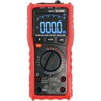
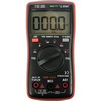
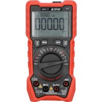
- LCD
- measurement switch
- measurement jack
- control buttons
- NCV sensor
- measurement cables
LT
Read the operating instruction
This symbol indicates that waste electrical and electronic equipment (including batteries and storage cells) cannot be disposed of with other types of waste. Waste equipment should be collected and handed over separately to a collection point for recycling and recovery, in order to reduce the amount of waste and the use of natural resources. Uncontrolled release of hazardous components contained in electrical and electronic equipment may pose a risk to human health and have adverse effects for the environment. The household plays an important role in contributing to reuse and recovery, including recycling of waste equipment. For more information about the appropriate recycling methods, contact your local authority or retailer.
The multifunction meter is a digital measuring instrument designed to measure various electrical quantities.
Before using the meter, read the instruction manual in its entirety and keep it for later use.
The meter features a plastic housing, a liquid crystal display, and a measuring range switch. The housing has measurement jacks fitted. The meter comes with measurement cables terminated with plugs. The meter is sold without a battery.
ATTENTION! This meter is not a measuring instrument within the meaning of the Trade Metrology Act.
TECHNICAL DATA
Display: 4 digit LCD – maximum displayed result: 4000
Sampling frequency: 3 samples per second
Overload symbol: "OL" symbol displayed
Polarity symbol: “−” sign displayed before the measurement result
Battery: 2 x AAA; 3V
Operating temperature: 0 ÷ 40°C at relative air humidity <75%
Storage temperature: -10^ ÷ +50^ at relative air humidity <80%
Outer dimensions: 120 x 60 x 33 mm
Weight (without batteries): 115 g
CAUTION! It is forbidden to measure electrical values exceeding the maximum measuring range of the meter.
| DC voltage | |||
| Range Resolution | Maximum Accuracy | ||
| 40 mV 0.01 mV | 600 V | ±(0.5% + 3) | |
| 400 mV 0.1 mV | |||
| 4 V 0.001 V | |||
| 40 V 0.01 V | |||
| 400 V 0.1 V | |||
| 600 V 1 V 400 mV | |||
EN
| Alternating voltage ( f_IN = 40 Hz - 1 kHz) | |||
| Range Resolution | Maximum Accuracy | ||
| 40 mV 0.01 mV | 600 V | ± (1.0% + 3) | |
| 400 mV 0.1 mV | |||
| 4 V 0.001 V | |||
| 40 V 0.01 V | |||
| 400 V 0.1 mV | |||
| 600 V 1 V 400 mV | |||
| Direct current Alternating current (f IN = 40 Hz - 1 kHz) | |||||||
| Range Resolution Maximum Accuracy Range Resolution Maximum Accuracy | |||||||
| 40 mA 0.01 mA | 400 mA 0.1 mA | ±(1.2% + 3) | 40 mA 0.01 mA | 40 mA 0.01 mA | 40 mA | ±(1.5% + 3) | |
| 400 mA 0.1 mA 400 mA 0.1 mA | |||||||
| 4 A 0.001 A | 10 A | 4 A 0.001 A | 4 A 0.001 A | 10 A | |||
| 10 A 0.01 A | A 0.01 A | ||||||
| Resistance | |||
| Range Resolution | Maximum Accuracy | ||
| 400 Ω | 0.1 Ω | ±(0.5% + 3) | |
| 4 kΩ | 0.001 kΩ | ||
| 40 kΩ | 0.01 kΩ | 40 MΩ | |
| 400 kΩ | 0.1 kΩ | ||
| 4 MΩ | 0.001 MΩ | ||
| 40 MΩ | 0.01 MΩ | ±(1.5% + 3) | |
EN
| Frequency | |||
| Range Resolution | Maximum Accuracy | ||
| 4 Hz 0.001 Hz | ±(1% + 2) | ||
| 40 Hz 0.01 Hz | |||
| 400 Hz 0.1 Hz | |||
| 4 kHz 0.001 kHz 3 MHz | |||
| 40 kHz 0.01 kHz | |||
| 400 kHz 0.1 kHz | |||
| 3 MHz 0.001 MHz ±(1.5% + 3) | |||
Accuracy: ± % of the indication + weight of the least significant digit
ATTENTION! Before opening the instrument housing, disconnect the measurement cables and turn off the meter to avoid the risk of electrocution.
Safety instructions
Do not operate the meter in an atmosphere with excessive humidity or in the presence of toxic or flammable vapours, or in an explosive atmosphere. Before each use, check the condition of the meter and the measurement cables. In case of noticing any faults, do not start operation. Replace damaged leads with new ones, free from defects. If in doubt, contact the manufacturer. During measurement, hold the test leads only by the insulated sections. Do not touch the measurement points or unused jacks of the meter. Disconnect the measurement cables before changing the measured quantity. Never carry out maintenance work without ensuring that the measurement cables have been disconnected from the meter and that the meter itself has been turned off.
Replacing the battery
The multimeter requires batteries, the number, and type of which are defined in the technical data section. It is recommended to use alkaline batteries. To install the batteries, open the instrument housing or the battery compartment cover on the underside of the meter. It may be necessary to remove the cover on the meter housing before accessing the battery compartment. Connect the battery according to its terminal marking and close the housing or battery compartment cover. If a battery symbol appears on the screen, the batteries must be replaced. To ensure measurement accuracy, it is recommended to replace the batteries as soon as possible, after the battery symbol appears.
Fuse replacement
The device uses a fast-acting safety fuse. In case of damage, replace the fuse with a new one with
EN
identical electrical parameters. To do so, open the meter's housing, following the same procedure as for battery replacement and the safety rules, and replace the fuse with a new one.
Switching the meter on and off
Set the measurement switch to the OFF position to turn the meter off. The remaining switch positions activate the meter and make it possible to select the measurement quantity and its range. The meter will turn off automatically, if not in use. After approximately 15 minutes of inactivity, the meter will turn off automatically. This will reduce battery consumption. The user will be notified by a sound signal, approximately one minute before the power supply is turned off. If the meter turns off automatically, pressing the SEL button will restore the meter to operation.
SEL button
The button is used to select measurement quantity in the case of the settings of the main switch described using few quantities. Change the measurement quantity by pressing this button.
HOLD/\* button
The button is used to retain the measured value on the display. When pressed, the button will keep the currently displayed value on the display, even after the measurement is over. Press the button again to go back to the measurement mode. The operation of the function is indicated on the meter display with the "HOLD" message. Holding the button for approx. 2 seconds will activate the display illumination / LED light. Press the button again and hold it for approx. 2 seconds to turn off the display illumination / LED light.
Connecting the measurement cables
If the cable plugs are capped, remove the caps before plugging the cables into the jacks. Connect the measurement cables in accordance with the instructions provided in the manual. Next, remove the measuring section caps (if any) and proceed with the measurements.
Built-in buzzer
The meter has a built-in buzzer that beeps briefly each time the selector knob is turned or a button is pressed to confirm the action has taken place. The buzzer will emit several sound signals per minute before the meter is automatically switched off and one long signal immediately before it is automatically switched off. The meter switches off automatically 15 minutes after the button has last been pressed or the selector knob's position has been changed.
MEASUREMENT PROCEDURE
Depending on the current position of the range switch, the display shows four significant digits. If the battery needs to be replaced, the multimeter indicates this by showing the battery symbol on the display. If the sign “-” appears on the display before the measured value, it means that the measured value has a reversed polarity relative to the meter's connection. If an overload symbol
EN
appears on the display, it means that the measurement range has been exceeded and it must be increased.
In the case of measurements of unknown values the meter should be set to the AUTO mode, in which case it determines the best measuring range by itself. If the selector knob is set to measure AC current or voltage, the meter will start measuring in the True RMS mode. This means that the real effective value of the alternating wave will be measured. If a non-sine wave is measured, the actual RMS value for that particular wave will be displayed. Special care should be taken when measuring quantities within the highest voltage range to avoid electric shock.
ATTENTION! Never allow the measuring range of the meter to be smaller than the measured value. This can damage the meter and cause electrocution.
The correct connection of the cables:
The red cable goes in the VΩHz or 10A jack
The black cable goes in the jack marked COM.
Ensure the optimum measurement conditions in order to achieve the highest possible accuracy of measurement. The ambient working temperature should be in the range from 18 to 28°C and relative air humidity <75%.
Example of accuracy determination
Accuracy: ± (% of the indication + weight of the least significant digit)
Measurement of DC voltage: 1.396 V
Accuracy: ±(0.8% + 5)
Error calculation: 1.396 × 0.8% + 5 × 0.001 = 0.011168 + 0.005 = 0.016168
Measurement result: 1.396 V ± 0.016 V
Voltage measurement
Connect the measurement cables to the V Hz and COM jacks. Set the main switch to the voltage measurement position (V). Press the SEL button to select the type of voltage to be measured. Connect the measurement cables in parallel to an electrical circuit and read the voltage measurement result. Never measure voltage that is higher than the maximum measurement range. This can damage the meter and cause electrocution. After selecting the lowest measurement range and when the measurement cables are disconnected, a changing measurement value can be seen on the display. It is a normal phenomenon. To eliminate it, it is enough to put the tips of test leads together. While measuring the AC voltage, press the button to measure the voltage with variable frequency.
Current intensity measurement
Depending on the expected current intensity value, connect the measurement cables to the V Hz and COM jacks or to the 10A and COM jacks. Select the appropriate measurement range using the
EN
knob. The maximum intensity of the measured current at the V Hz jack can be 400 mA. In case of measuring current above 400 mA, connect the cable to the jack marked 10A. The maximum intensity of current measured in the 10A jack may be 10 A. The measuring time for currents higher than 4 A should not exceed 15 seconds. After that, there must be a 3-5-minute break at a minimum before the next measurement. The V Hz jack can be loaded with a maximum current of 400 mA. It is forbidden to exceed the maximum values of current and voltage values for a given jack. The measurement cables should be connected in series to the tested electrical circuit. Select the type of current measured using the selector knob and read the measurement result. The meter will automatically select the appropriate measuring range, which can be changed by pressing the "SEL" button, if necessary.
Resistance measurement
Connect the measurement cables to the V Hz and COM jacks and set the range switch to the resistance measurement position marked with the symbol. Connect the test leads to the terminals of the measured component and read the measurement result. For measurements greater than 1 M , the measurement may take a few seconds before the readout becomes stable, which is the normal response for high resistance measurements. Before applying the tips to the terminals of the measured component, an overload symbol is shown on the display. It is absolutely forbidden to measure the resistance of components through which electric current flows or of charged capacitors.
Conductivity test
Connect the measurement cables to the V Hz and COM jacks. Turn the selector knob to the buzzer symbol. If the meter is used to measure conduction, the built-in buzzer will sound whenever the measured resistance drops below 50 . The buzzer can also emit a sound when the resistance is in the range from 50 to 100 . It is absolutely forbidden to test conductivity in circuits through which electric current is flowing.
Diode test
Connect the measurement cables to the jacks marked "INPUT" and "COM" and turn the selector knob to the diode symbol. Now connect the measuring terminals to the diode leads, according to the direction of conduction and in the reverse direction. If the diode is working, it will show a voltage drop in its forward direction expressed in mV. If connected in the reverse direction, the display will show the overload symbol. Working diodes are characterized by a low resistance in the forward direction and a high resistance in the reverse direction. It is absolutely forbidden to test diodes through which electric current is flowing.
Frequency measurement
Connect the measurement cables to the V Hz and COM jacks. Turn the selector knob to the position marked "Hz". Select the frequency measurement option with the SEL button. The display will show the "Hz" symbol. Read the measurement result on the display.
EN
Non-contact AC voltage detection
The meter has a sensor that can detect the electromagnetic field generated by AC voltage. Turning the selector knob to the position marked “NCV” will be confirmed by the display showing “NCV”. Bring closer the NCV sensor in the front plate of the meter to the point to be checked in terms of electromagnetic field presence. The greater the detected electromagnetic field, the faster the buzzer sound will be. This measurement can be used, for example, to detect hidden AC voltage wires. However, it should be remembered that such a measurement is affected by many external factors and may be disturbed by external electromagnetic fields. Do not rely solely on this method to detect live wires.
Contact voltage detection
Turn the selector knob to the „NCV” position. Connect the single cable to the VΩHz jack. Bring the test lead into contact with the component to be measured. If it is live, the buzzer will sound.
MAINTENANCE AND STORAGE
Wipe the meter with a soft cloth. Larger amounts of dirt should be removed with a slightly damp cloth. Do not immerse the meter in water or any other liquid. Do not use solvents, or corrosive or abrasive agents for cleaning. Care should be taken to keep the contacts of the meter and the measurement cables clean. Clean the contacts of the measurement leads with a cloth slightly soaked in isopropyl alcohol. In order to clean the contacts of the meter, turn off the meter and remove the batteries. Turn the meter over and shake it gently so that larger pieces of dirt fall out of the meter connectors. Lightly soak a cotton swab in isopropyl alcohol and clean each contact. Wait for the alcohol to evaporate and then install the batteries. The meter should be stored in a dry room, inside the supplied unit packaging.
DE
GERÄTEBESCHREIBUNG
ÚDRŽBA A USCHOVÁVANIE
Merač utierajte mäkkou handričkou. Väčšie nečistoty odstraňujte jemne navlhčenou mäkkou handričkou. Prístroj neponárajte do vody ani do inej kvapaliny. Na čistenie nepoužívajte rozpúšt'adlá, leptavé ani drsné prostriedky. Starajte sa o čistotu kontaktov prístroja a meracích káblov. Kontakty meracích káblov čistite handričkou jemne navlhčenou izopropylalkoholom. Ked' chcete vyčistiť kontakty multimetra, vypnite ho a vyberte batérie. Multimeter obrát'te a jemne ním potraste tak, aby väčšie nečistoty vypadli z jeho konektorov. Vatové tyčinky jemne navlhčite izopropylalkoholom a vyčistite každý kontakt. Počkajte, kým sa alkohol vyparí, a následne namontujte batérie naspät'. Multimeter uchovávajte v suchej miestnosti v dodanom (originálnom) kusovom balení.
HU
ESZKÖZ JELLEMZÖI
Calcularea erorilor: 1.396 x 0.8% + 5 x 0.001 = 0.011168 + 0.005 = 0.016168