YT-73097 - Multimeter Yato - Free user manual and instructions
Find the device manual for free YT-73097 Yato in PDF.

| Product Type | Digital Multimeter |
| Brand | Yato |
| Model | YT-73097 |
| External Dimensions | 185 x 88 x 52 mm |
| Weight (without batteries) | 305 g |
| Power Supply | 2 AA batteries (1.5 V each) |
| Display | LCD 4 digits (max 9999) |
| Sampling Frequency | Approximately 2 to 3 times per second |
| Fuses | F600 mA/250 V and F10 A/250 V (fast-blow) |
| Operating Temperature | 0 to 40 °C, relative humidity < 70 % |
| Storage Temperature | -10 to +50 °C, relative humidity < 85 % |
| Main Functions | DC/AC voltage, DC/AC current, resistance, capacitance, frequency, diode test, continuity test, temperature, non-contact voltage detection (NCV), battery test, duty cycle measurement |
| Maximum Voltage Ranges | 1000 V DC, 750 V AC rms |
| Input Impedance | Approximately 10 MΩ |
| Overload Protection | Fuses and electronic limiting |
| Auto Power Off | After approximately 15 minutes of inactivity |
| Included Accessories | Test leads, type K thermocouple (up to 230 °C) |
| Maintenance and Cleaning | Soft cloth, isopropyl alcohol for contacts |
| Storage | Dry place, in original packaging |
| Battery Replacement | Open compartment under the device, observe polarity |
Frequently Asked Questions - YT-73097 Yato
User questions about YT-73097 Yato
0 question about this device. Answer the ones you know or ask your own.
Ask a new question about this device
Download the instructions for your Multimeter in PDF format for free! Find your manual YT-73097 - Yato and take your electronic device back in hand. On this page are published all the documents necessary for the use of your device. YT-73097 by Yato.
USER MANUAL YT-73097 Yato
- case
- handle
- collector
- switch
- socket wrench
LT
1.korpusas
2. rankena
3. griebtuvas
4. tinklo jungiklis
5. ziedenis raktas
H
This symbol indicates that waste electrical and electronic equipment (including batteries and storage cells) cannot be disposed of with other types of waste. Waste equipment should be collected and handed over separately to a collection point for recycling and recovery, in order to reduce the amount of waste and the use of natural resources. Uncontrolled release of hazardous components contained in electrical and electronic equipment may pose a risk to human health and have adverse effects for the environment. The household plays an important role in contributing to reuse and recovery, including recycling of waste equipment. For more information about the appropriate recycling methods, contact your local authority or retailer.
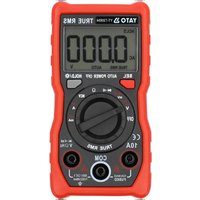
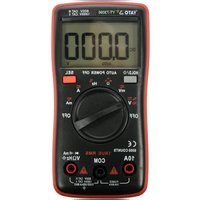
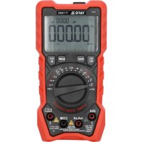
The multifunction meter is a digital measuring instrument designed to measure various electrical or physical quantities. The meter has a plastic housing, liquid crystal display, and a range/measurement quantity switch. The housing has measurement jacks fitted. The meter comes with measurement cables terminated with plugs. The meter is sold without a battery.
Before using the meter, read the instruction manual in its entirety and keep it for later use.
CAUTION! This meter is not a measuring instrument within the meaning of "the Trade Metrology Act".
TECHNICAL DATA
Display: 4 digit LCD - maximum displayed result: 9999
Sampling frequency: approx. 2-3 samples per second
Overload symbol: an "OL" symbol displayed
Polarity symbol: a “-” sign displayed before the measurement result
Battery: 2 × AA ( 2 × 1.5V )
Fuse: F600mAh250V (fast-acting); F10AL250V (fast-acting)
Working temperature range: 0^ to 40^ at relative air humidity < 70%
Temperature at which the declared accuracy is maintained: 18^ to 28C at relative air humidity < 70%
Storage temperature: -10^ ÷ +50^ at relative air humidity < 85%
Outer dimensions: 185 × 88 × 52 ~mm
Weight (without batteries): 305 g
CAUTION! It is forbidden to measure electrical values exceeding the maximum measurement range of the meter.
| DC voltage AC voltage | |||||
| Range Resolution | Upton Accuracy Range Resolution | Resolution Accuracy | |||
| 999.9 mV 100 μV | ±(0.5% + 3) 99.99 V | 999.9 mV 100 μV | ±(0.8% + 3)9.99 | ||
| 99.99 V 10 mV | 10 mV | ||||
| 999.9 V | 100 mV | 750 V | 100 mV ±(1.2% + 3) | ||
| Overload protection: 1000 V DC or 750 V AC RMS | True RMS measurement for input impedance approx. 10 MΩ. Frequency of the measured signal 40 ÷ 1000 Hz. Maximum input voltage 750 V AC. (eff ective value) | ||||
| Alternating current | Direct current | ||||
| Range | Resolution | Accuracy | Range | Resolution | Accuracy |
| 99.9 mA | 0.1 μA | ±(1.0% + 3) | 99.9 mA 0.01 | mA | ±(0.8% + 3) |
| 600 mA 1 μA | 99.99 mA 0.01 | mA | |||
| 600 mA | 0.1 mA | ||||
| 10 A | 0.01 A | ±(1.5% + 3) | 10 A | 0.01 A | ±(1.2% + 3) |
| Overload protection: μA/mA range - 630 mA/250 V fuse; 10 A range: 10 A/250 V fuse. Max. input current mA connector: 600 mA; 10A connector: 10 A. Frequency of the measured signal: 40 ÷ 1000 Hz. | Overload protection: μA/mA range - 630 mA/250 V fuse; 10 A range: 10 A/250 V fuse. Max. input current mA connector: 600 mA; 10A connector: 10 A | ||||
GB
| Resistance Capacitance | |||||
| Range Resolution | U10 Accuracy Range | Resolution Accuracy | |||
| 999.9 Ω 0.1 | Ω | nF ±(0.8% + 3) | 9.999 nF 0.001 nF ±(4.0% + 30) | ||
| 9.999 kΩ 0.01 kΩ 99.99 nF 0.01 | ±(4.0% + 3) | ||||
| 99.99 kΩ 0.01 kΩ 999.9 nF 0.1 | |||||
| 999.9 kΩ 0.1 kΩ | 9.999 μF | 0.001 μF | |||
| 9.999 MΩ 0.001 MΩ | 99.99 μF | 0.01 μF | |||
| 99.99 MΩ 0.01 MΩ | ±(1.2% + 5) | 999.9 μF 0.01 μF | |||
| 9.999 mF 0.001 mF | |||||
| 99.99 mF 0.001 mF ±(5.0% + 30) | |||||
| Diode test | Frequency | ||
| Measurement range: 0.15 – 3 V | Range | Resolution | Accuracy |
| 9.999 Hz – 9.999 MHz | 0.001 Hz – 0.01 MHz | ±(1.0% + 3) | |
| Conduction current approx. 1 mA; open circuit voltage: 3.2 V. The measurement shows the approximate voltage drop of the diode conduction. | Input voltage range 200 mV ÷ 10 V AC RMS; Protection 600 V AC/DC | ||
| Continuity test |
| Measurement range: 100 Ω |
| Open circuit voltage: 1 V |
| Temperature | ||
| Range | Resolution | Accuracy |
| -20°C to +1000°C | 1°C | ±(1.0% + 3) |
| -4°F ÷ +1832°F | 1°F | |
| Overload protection 600 V AC/DC. Accuracy does not allow for thermocouple error. The stated accuracy is valid for ambient temperature changes of not more than ± 1°C. If the ambient temperature changes ±5°C, the specified accuracy is achieved after 1 hour. | ||
| NCV – non-contact AC voltage detection | Battery test | ||
| Range | Description | Range | Description |
| Low field | Indication “L”, NCV indicator lights up green, buzzer emits an acoustic signal | 1.5 V | The load resistance is approx. 30 Ω, the indicator shows the battery voltage |
| High field | Indication “H”, NCV indicator lights up red (two diodes), buzzer emits an acoustic signal | 9 V | The load resistance is approx. 300 Ω, the indicator shows the battery voltage |
Accuracy: ± (\% of the indication + weight of the least significant digit)
CAUTION! Before opening the instrument housing, disconnect the measurement cables and turn off the meter to avoid the risk of electrocution.
GB
Safety instructions
Do not operate the meter in an atmosphere with excessive humidity or in the presence of toxic or flammable vapours, or in an explosive atmosphere. Before each use, check the condition of the meter and the measurement cables. In case of noticing any faults, do not start operation. Replace damaged cables with new ones, free from defects. If in doubt, contact the manufacturer. During measurement, hold the measurement cables (tips) only by the insulated sections. Do not touch the measurement points or unused jacks of the meter. Disconnect the measurement cables before changing the measured quantity. Never carry out maintenance work without ensuring that the measurement cables have been disconnected from the meter and that the meter itself has been turned off.
Replacing the battery
The multimeter requires batteries, the number, and type of which are defined in the technical data section. It is recommended to use alkaline batteries. To install a battery, open the instrument housing or the battery compartment cover on the underside of the meter. Before accessing the battery compartment, it may be necessary to remove the cover on the meter housing. Connect the battery according to its terminal marking, close the housing or battery compartment cover. If a battery symbol appears on the screen, the battery must be replaced. It is recommended to replace the battery as soon as possible, after the battery symbol appears, to ensure measurement accuracy.
Fuse replacement
The instrument uses a fast-acting safety fuse. In case of damage, replace the fuse with a new one with identical electrical parameters. To do this, remove the flexible housing cover, remove all screws fixing the two parts of the housing and open the meter housing, replace the fuse with a new one. The parameters of the fuse are indicated on the fuse housing. When replacing both fuses, it is recommended to replace the fuses one by one, so as not to change them with places.
Turning the meter on and off
Set the measurement switch to the OFF position to turn the meter off. The remaining switch positions activate the meter and make it possible to select the measurement quantity and its range. The meter has a function of automatic turning off in case of inactivity of the user; after about 15 minutes from the last user's reaction, the meter will turn off automatically. This will reduce battery consumption. If the meter turns off automatically, pressing the SEL or V.F.C button restores the meter to operation.
SEL button
Press the button to select measurement quantity in the case of the settings of the main switch described using few quantities. Change the measurement quantity by pressing this button.
V.F.C button
It is a button to measure the voltage for the changing frequency of the measured signal. Start the measurement by pressing the button.
Flashlight symbol button
It is a button to turn on and off a small flashlight located in the front panel of the housing. The flashlight is designed to illuminate the workplace.
HOLD button
The button is used to retain the measured value on the display. When pressed, the button will keep the currently displayed value on the display, even after the measurement is over. Press the button again to go back to the measurement mode. The operation of the function is indicated on the meter display with the HOLD sign.
Connecting the measurement cables
If the measurement cable plugs are capped, remove the caps before plugging the measurement cables into the jacks.
Connect the measurement cables in accordance with the instructions provided in the manual. Next, remove the caps (if any) on the measuring section and proceed with the measurements.
MEASUREMENT PROCEDURE
Depending on the current position of the range switch, the display shows four digits. If the battery needs to be replaced, the multimeter indicates this by showing the battery symbol on the display. If the sign “-” appears on the display before the measured value, it means that the measured value has a reversed polarity relative to the meter's connection. If an overload symbol appears on the display, it means that the measurement range has been exceeded and it must be increased. If the scale of the measured value is not known, set the highest measurement range and reduce it after reading the measurement value. The measurement of small quantities with a high measurement range involves the greatest measurement error. Special care should be taken when measuring within the highest voltage range in order to avoid electrocution.
CAUTION! Do not allow the measurement range of the meter to be smaller than the measured value. This can damage the meter and cause electrocution.
The correct connection of the cables:
The red cable goes in the jack marked VΩHz% or μAmA or 10A
The black cable goes in the jack marked COM
Ensure the optimum measurement conditions in order to achieve the highest possible accuracy of measurement. The ranges of temperature and humidity are given in the technical data.
Example of accuracy determination
Accuracy: ± (% of the indication + weight of the least significant digit)
Measurement of DC voltage: 1.396 V
Accuracy: ± (0.8% + 5)
Calculation of error: 1.396 × 0.8% + 5 × 0.001 = 0.011168 + 0.005 = 0.016168
Measurement result: 1.396V± 0.016V
Voltage measurement
Connect the measurement cables to the jacks marked VΩHz% and COM. Set the main switch to the voltage measurement position (V). Press the SEL button to select the type of voltage to be measured. Connect the measurement cables in parallel to an electrical circuit and read the voltage measurement result. Never measure voltage that is higher than the maximum measurement range. This can damage the meter and cause electrocution. After selecting the lowest measurement range and when the measurement cables are disconnected, a changing measurement value can be seen on the display. It is a normal phenomenon. To eliminate it, it is enough to connect the tips of measurement cables with each other. While measuring the AC voltage, press the button to measure the voltage with variable frequency.
Current intensity measurement
Depending on the expected current intensity value, connect the measurement cables to the AmA and COM jacks or to the 10A and COM jacks. Select the appropriate measurement range using the knob. The maximum intensity of the measured current at the AmA jack can be 600mA . In case of measuring current above 600mA , connect the cable to the jack marked 10A. The maximum intensity of current measured in the 10A jack may be 10A . For this reason, the measuring time for currents higher than 5A should not exceed 10 seconds; after that, there must be a 3-5-minute break at a minimum before the next measurement. The AmA jack can be loaded with a maximum current of 600mA . It is forbidden to exceed the maximum values of current and voltage values for a given jack. The measurement cables must be connected in series to the tested electrical circuit. Select the range and type of measured current by means of the switch and read the measurement result. Start by selecting the maximum measurement range. In order to obtain more accurate measurement results, change the measurement range if necessary.
Resistance or capacitance measurement
Connect the measurement cables to the jacks marked VΩHz% and COM and set the range switch to the resistance (Ω) or capacitance (||) measurement position. Connect the measurement cables to the terminals of the measured element and read the measurement result. In order to obtain more accurate measurement results, change the measurement range if necessary. It is absolutely forbidden to measure the resistance of components through which
GB
electric current flows or of charged capacitors. For measuring high resistance resistors or high capacitance capacitors the measurement may take a few seconds for the result to stabilise; this is a normal reaction when measuring large values. In the resistance measurement mode, before applying the measuring tips to the measured element, an overload symbol is shown on the display.
Diode test/conduction test
Connect the measurement cables to the jacks marked VΩHz% and COM and set the selector to the diode symbol. By default, this mode measures the continuity of the electrical circuit; after pressing the SEL button you can test the diodes. Pressing the SEL button again allows entering automatic mode, where the meter itself selects whether to test the diodes or measure continuity. Press the SEL button again to return to the conduction measurement. Apply the tips of the measurement cables to the ends of the measured element. In the case of a conduction test, the continuity of the cable will be indicated by a buzzer. If the resistance of the circuit under test is between 15 Ω and 30 Ω, the green indicator lamp will light up and the buzzer will emit an intermittent signal. In the case of testing diodes, the display shows the value of the conduction voltage, usually 0.5-0.8 V or the symbol "OL" if the diode is tested in the negative direction. In automatic mode, if the resistance of the measured element is in the range of 15 Ω to 100 Ω then the meter tests the conduction. It is absolutely forbidden to test diodes or conduction if an electric current flows through the circuit under test.
Frequency measurement / Fill factor measurement
Connect the measurement cables to the jacks marked VΩHz% and COM. Set the selector to the position marked Hz%.
The display shows simultaneously the result of the frequency measurement and the fill factor of the measured signal.
Temperature measurement
Move the measurement switch to the temperature measurement position (^ / ^) . The display will show the ambient temperature around the meter. It is also possible to connect the thermocouple terminals to the V Hz% and COM jacks. The thermocouple supplied with the product permits measurement of only up to 230^ . To measure higher temperatures, a thermocouple designed for measuring higher temperatures must be purchased. Use type K thermocouples. With the SEL button, you can select either the ^ or ^ measurement unit. The default temperature measurement unit is ^ .
Non-contact AC voltage detection
The meter has a sensor that can detect the electromagnetic field generated by AC voltage. Move the selector to the NCV position, this will be confirmed by the "NCV" display indicator and the "----" symbol. Bring closer the NCV sensor in the front plate of the meter to the point to be checked in terms of electromagnetic field presence. If a field of low intensity is detected, the meter will display the "---L" symbol, the green diode lights up. If a high intensity electromagnetic field is detected, the meter displays the "---H" symbol, the red diode lights up and sound is emitted by the buzzer. This measurement can be used, for example, to detect hidden AC voltage wires. However, it should be remembered that such a measurement is affected by many external factors and may be disturbed by external electromagnetic fields. Do not rely solely on this method to detect live wires.
Contact voltage detection
Move the selector to the "Live" position, connect a single cable to the VΩHz% jack. Apply the measuring tip to the measured element, if it is live, the display will show the "LIVE" symbol, the green indicator lamp lights up and an acoustic signal is emitted by the buzzer.
LEAD message
The LEAD message appears on the screen when you try to measure with test leads that are not properly connected to the meter's sockets. For example, trying to measure electric voltage with the wires connected, as if measuring current. When the LEAD message appears on the meter display. Turn off the meter, check whether the test leads are connected to the appropriate meter sockets and the selector indicates the correct measurement value. Then turn the meter back on and repeat the measurement.
GB
MAINTENANCE AND STORAGE
Wipe the meter with a soft cloth. Larger amounts of dirt should be removed with a slightly damp cloth. Do not immerse the meter in water or any other liquid. Do not use solvents, corrosive or abrasive agents for cleaning. Care should be taken to keep the contacts of the meter and the measurement cables clean. Clean the contacts of the measurement cables with a cloth slightly soaked in isopropyl alcohol. In order to clean the contacts of the meter, turn off the meter and remove the battery. Turn the meter over and shake it gently so that larger pieces of dirt fall out of the meter connectors. Lightly soak a cotton pad with isopropyl alcohol and put it on a stick and clean each contact. Wait for the alcohol to evaporate and then install the battery. The meter should be stored in a dry room, inside the supplied unit packaging.
GERÄTEBESCHREIBUNG
TEXHIYHXAPAKTEPNUCTUKN
Диспл徴:ЖК 4цфрн-мakcmaьн BiiodpaqkyBaHn pe3yntaT:9999
Yactota dnckpertn3aui: 6n3bko 2-3 pa3ib Ha cekyHny
3HaK nepeBaHTaxeHHa: BiO6paXacTbcnMBOI «OL»
3HaK noJyRHOCTi: BiO6paXaEcTbcra CnBON «-» nepei pe3yIbTaTOM BmIpHOBaHHA
Batape: 2 x AA (2 x 1,5 V)
3an06iknK.F600mAH250V(BncoKa WbNdkicTb);F10AL250V(BncoKa WbNdkicTb)
Poboua Temnepatya: 0÷ 40 rp.C; npu BiDnochin Bonorocti < 70%
TemnepaTpa, npn kki 6ynde nldpmyBaTncs3aBHeHa ToHicb: 18 ÷ 28 rp. C; npn BiDHOChI BONORcTi <70%
Temnepatypa 36epiraHHa: Bnue -10 ct. C ÷ +50 rp. C; npu BiHochi Bonorocti <85%
3OBHIiHIpO3MpI:185x88x52MM
Bara (6e3 6aTapeiok): 305 r
YBAGA! 3a6opohacbca Bmipobatn eJeKtpnHi 3NaueHH, 0o nepeBnuyotb MaKcHMaIbHn diana3OH Bmipobahb MyIbTtMeTp.
HaTnCKaHHK KONIKI D03BONJ E Bn6paTN 3NaueHHN BmMIPIOBaHH NJI napameTpIB rOIOBHOrO nepeMnKaay, ONUCAHIX DeKiJIbKOMA 3NaueHHaMM. 3MiHa PO3Mipy BmMIPIOBaHH 3dIChHOCTbcra IJXOM HATnCKaHH NJIeIKN.
KHONKa V.F.C
KhoNka BmipobAHnHa npyri 3miHn yactOTn BmipobHOcHany. BmipobHHn noHnaetbca HATnCKaHHM KhoNk.
PpabnIbHe nIDKnIOueHHnpoBODIB:
YerboHn npoBid do rhi3da 3 MapkyBaHHaM VΩHz% a6o μAmA a6o 10A
UopHnKa6eBJdo rHi3da 3 MapkyBaHHM COM
OtpmataMakcmaNbHO MOxNBy ToHicb BmipobAHn, NOBHHi 3a6e3neueHi ONTImaJIbHi yMOBN BMIpOBaHH. Diana3OH TemnepaTypn i BONorocI HabeDeHO B npepiKy TexHnX daHnx.
PpuKnaad eU3NaueHn moHocmi
ToHicTB: ± (% nOKa3aHH + BarHaIMeHs 3NaHooIu
BmipnoBaHnNoctiHoHa npy:1,396V
ToCHtB: ±(0,8% + 5)
PozpaxyHok norpuiHocTi: 1,396 x 0,8% + 5 x 0,001 = 0,01168 + 0,005 = 0,016168
Pe3yIbTaT BmIpIOBaHHa:1,396B±0,016B
BumipioBaHHa Hanpyau
PiKIOHtB BmipOBaHbHI Ka6eni Do po3'emib 3 MapkyBaHHm VΩHz% i COM. BcTaHOiB roIobHn BmHKauy noIooKeHH BmIPOBaHH HAnpyr (V). Bn6epitb xapaKTe HAnpyr, kcy cnid BmipAITn, HATNCHyBun KhoNkY SEL. PiKIOUHTB BmIPOBaHbHI npoBOJn napaneJIbHO Do eNeKtpuHoro IanlOra i nepeBipTe pe3yIbTat BmIPOBaHH HAnpyr. HikOn He BmIPouTe HAnpyr BUnSe MAKCImaHbORO diana3OHy BmIPOBaHH. Ze Moze npNBecTN do 3HnueHH MyLTImetpa i ypaxeHH eNeKtpuHm CTPymOM. Pic7 Bn6Opy HauHHQTO diana3OHy BmIPOBaHH Ta HeBicIKIQUeHHx BmIPOBaBHx npoBOJB Ha DncIIneI Moxe BiO6paxKaTncs 3MInHe 3NaeHHB BmIPOBaHH. Lc HopMaJIbHe RaNSe, dny Noro ycyeHH NocTaTHBo BKOpOTn KINCI BmIPOBaBHx npoBDiB pa3OM. Pd Yac BmIPOBaHH HAnpyr 3MiHNO CTpyMy HATNCiTB KHONKy dny BmIPOBaHH HAnpyr 3MiHNO CTpyMy.
BumipioBaHHa Cmpymy
3aIexHo BID oukyBaHOro 3NaueHnB BMIpOHaHO CTpyM NiKIOuHt BmipOBAhHi npOBOn Do rHizda AmA i COM do rHizda 10A i COM. Bn6epiB BiNobIHn Diana3OH BMIPy 3a Donomoro pUck. MAcImaJIbHe 3NaueHnB BMIpOHaHO CTpyM BnH3Di AMe MOx e CTAHOBTN 600 mA, pnBmipOBAHHI CTpyM BnSe 600 mA, nIKIOuyt Ka6eBdo rHizda 3 MapKyBaHHam 10A. MaKcIMaJIbHe 3NaueHnB BMIpOHaHO CTpyM B rHizdi 10A MoXe CTAHOBTN 10 A, aIe Yac BmipOBAHHa CTPMy BnSe HIX 5A He MoXe NpeBnSyBaTn 10 cek., npUOMy nepeH hAcTyHNBM IMipOM cIid 3po6HTN nepeBy He MeHwe 3 - 5 XBNIN. TnI3do AMe MOx e Byn HabaTaeHO MaKcIMaJIbHM CTpyMOM 600 mA. 3abOpOHCTbcra NepeBnSyBaTn MaKcIMaJIbHI 3NaueHnC TpyMIB I Hanpyr dIy daHO rHizda BmipOBAhHi npOBOn NobHHI 6byt NiKIOUeHI NocIIOBHO Do BInpObYBaHO eEKeTpNUHO NaIzUra, Bn6epiB DiAna3OH i TnBmipOBAHO CTpyM 3a Donomoro IO nepeMkaua i 3HTaIte pe3yIbTat BMIpOBAHH. CIId NowATN BMIpOBAHHa 3 BVbOpy MaKcIMaJIbHO Diana3OH BMIpOBAHHa. Bn MoXeTe 3MiHTn Diana3OH BMIPy, Uo6 otPIMAtn 6blb ToHni pe3yIbTaTn BMIpOBAHb.
UA
Bumipuobannn onopy a6o EMHocmi
PiKIOHITb BmipOBaJIbHI npOBoHn DO p03'EMIB 3 MapkyBaHHm VΩHz% i COM, nepemKau dianaoHIB BCTaHOBIb B noIOXeHHI BmipOBaHHa ONOpY (Ω) a6o EMHOCTi (II).PiKIOUHTb BmipOBaJIbHI HAKOHeuHKn DO KIeM BmipOBaHOro eJeMeHTa I npOHTaHT pe3yJbTaB BmipOBaHH. Bu MOKeTe 3MIHTn DIana3OH BmIPy, O6o OTpIMATn 6JIbTuO Hi pe3yJIbTaT BmIPOBaHB. A6COIoTHO 3a6OpOHeHO BmipOBaTH Onip eMeENTIB, Upe3 kpi npOTiKae ENEKTPnHn CTpyM a60 3apAIXeHHI KOHeHCATOpIB. DnB BmipOBaHH Pe3NCTOpIB 3 BeINKIM ONOPOM a60 KOHeHCATOpIB 3 BEINKO EMHCTHO BmIP MoKe 3aHRTN KInbKa CEkyHd Do TORO, Jk pe3yJIbTaT Cta6JIi3yETbcR, cE HopMaJIbHa peakzra B pa3i BmipOBaHB BnCOKHX 3NaueHb. YpeKMI BmipOBaHHa ONOpY, nepd npNKlaDaHHM BmipOBaJIbHNx HAKOHeuHKB DO BmIPOBaHOr eJeMeHTA, HaINcPJIe 3'ABNTbcr CmBOJ nepeBAHTaeHHJ.
Tecm diodie / mecm Ha npoibHicmb
ПдкнчыВИМIPOBaJIbHI npOBoIиdo po3'EmiB 3 МарКУВаHЯm VΩHz% i COM, сeNEKTop BCTahOBiTb Ha CUMBOJI cBITIOJODa. 3a 3AMOBUByBaHnM ue pexIM BImipIOE 6e3nepePBHicTB eNeKTPnUHO KOHTpy, nicIHa TnCKAHH KONKn SEL moXHa 6yde nepeBipTN CBITIOJODn. NOBtOpHe HATNCKAHn KONKn SEL do3BOJAE yBIiTn B ATOmatuHn pexIM, De BIMIPOBaB u6npaC ce6e, nepeBipRe cBITIOJODn a6o BmipIOe 6e3nepePBHicTB. NOBtOpHe HATNCKAHN KONKn SEL np3BeDe Do nobephenn Da BmipOBaHH npOBIDHOCTI. BmipOBaJIbHi hakoehNKn noBHHi byTu HaHeceHi Ha HakoehNKn DOcIjKvBaHO enemTa. Y pa3i TeCTy Ha npOBIDHcTB Ha 6e3nepePBHicTB npOBODY BKA3YBaTUME 3ByKOBu CNrHan 3ymepa. RaIoo onip DoCNIJxVbaHO KOHTpy cTAHOBT b Id 15 Om do 30 Om, 3aropaeTbcra 3eHnIH INdkaTOP, a 3ymep BuJaE nepePBUACTn CNrHan. Y pa3i TeCTy CbitIOIOIB Ha dncnneB iDobpaKaETBCa 3NaueHn HApyr npOBIDHOCTI, 3a3Buay 0,5-0,8 V a6o CmBOl «OL», RaIoo diO TeCTyETCBsry y 3BOPOTbOMy HApRMky ABOTMaTHUHOMy peKMI, RaIoo onip DoCNIJxVbaHO enemTa cTAHOBT b Id 15 Ω do 100 Ω, BmIPOBaU npEBipRe npOBIDHcTB. A6conHToHO 3abOpOHeHO TeCTyBaTn DiOn n abO npOBIDHcTB, KaIO uepe3 DocIqJyBaHn KOHTyp npotikac eJeKTPnHn CTpym.
BumipoeaHHaYacmomu/BumipoeaHHKoepiueHma3anoeHH
ПдкнчыВИМIPOBaHbHi Ka6eni Do po3'EmiB 3 МарКУВаHHЯm VΩHz% i COM. BCTaHOBiT b ceIeKTop y noJoxeHHa 3 no3Haquko Hz%. Ha dinCnnei OndHocHo BiObpaKaIOb cpe3yIbTaT BIMIPOBaHHa YactOTn Ta KoepiieHT 3anOBHeHHa BIMIPOBaHOrO CnHaNy.
BumipiobaHHmmepeamypu
Поверніть поемпач ВИМIPIOBAHну y NOLOженя ВИМIPIOBAHну Temnéратур n (^ / ^) .Ha dinспгі BIDOBpaKaTNMeTbСЯ Temnéратура habКOLишьOrO cepeДОВица ВИМIPIOBAч.Тakok можна пдкючатиdo po3etOK VΩHz% TaCOM KIemn Tepmonapu.Tepmonapa, su O BXODNTB B KOMNJIeK TnoCTaBKN,do3BOJЯБ WIMIPIOBaTn TiNbKn Do 230°C.Дя ВИМIPIOBAHн6iNbB WICOKnx Temnéратур nobHHa 6yTu nepeD6aYeHa Tepmonapa, npn3haYeHa Дя ВИМIPIOBAHн6iNbB WICOKnx Temnéратур.ВИКOPICTOBYte Tepmonapu TIny K.Bn6epiTB OdnHnIcTO WIMIPIOBAHнo C a6o F3a DonomorOToK HONKn „Select".OdINHnIa WIMIPIOBAHну Temnéратур n3a 3amOBuyBaHHm - °C.
B3Kohmhe BureHnHa np2u 3MHoOcmpymy
Bmipobay ma eatuk, knn 3dathn BnBnTne eneKtpomarHIThe none, 0o rehepyctbca 3miHIO HAnpyroIO. Pepemicttbc calektop y noIoxenHa NCV, ce 6yde niTBePdxByaTncs iHnKaTOpom dncnpeiNCV" Ta BnIMMm CmBONOM."---". HaBnxTe daTnK, no3NaueHn NCV, po3taWOBAHn Ha nepeHni naHeli Bmipobaua, do micra, kKe Heo6xIDHO nepeBipntu Ha haBnCtB eektpomarHITHO nOJa. Kaio 6yde BnABNeHO nOle Hn3bKOi IHTeHCNBHOCTi, Bmipobay BiO6pa3ntb CMBON «---L" i 3acBItntbc 3eHnN CBiTNOIOJ. Kaio 6yde BnABNeHO eektpomarHITHe nOJe BnCOKOi ITHCNIBHOCTi, Bmipobay BiO6pa3ntb CMBON «---H", 3arOpNTbcr YepBOHNI CBiTNOIOJ ta npolyHae 3ByKOBn CnHaJI. Ce BmipobAHn MoXHa BnKOpNCTOBYaTn, HanpNKlaI, dIy BnABNeHHn pInxOBaHX Ka6eINBmHORO CTpyMy. Ondak cnIq Nam'ATaTI, 0o Ha Take BmipobAHn BnNBAe 6Garato 3OBHIhIXΦakTopiB i BOHO MOKe npuywBaTcR 3OBHiShHMn eneKtpomarHITHMN NOJAMN. He nokndaaiTeec BnKlNoUHO Ha ue MeToD IINBnBHeHHn npOBODIB nI, HappyoIO.
Kohmakmhe bureeHnHa npyu
Iobephi b ceneKTopn nepemkauy noonxehna «Live", niKniouitb oDnH kaebI do po3eTKVΩHz%. IpnTnciB Bmipobalh n HakoheuHKdo elementA, kNn notpi6HO BmipaTn, kUo Ha dncnJIe 3 'Bntbcra CmboJ „LIVE", 3arOpTbc8 3eHn iHdkaTOp i npolyhae 3BykOBn cnHaI.
UA
nojodomneHRALEAD
IobidomneneHRALEAD 3'raBnaCTbcaHaekpHi, KOHNHAMaraTecra npOBectu BmipOBaHHa 3a donomoroBmipBOBaNbHx npoBodib, kI HnpaBnJIbHO nIKnOHei Do rHI3d rIOKometpa. HanpNKlaad, cnpo6a BmipAtn eJeKtpnHy Hanpyr3 nIKnOueHMn npoBODAMn, Hi6n BmipOpCtpyM. KOHN DaicnEe rIOKometpa 3'ABNcTBcnoBIDOMneHRALEAD. BmKnITb rIOKometp, nepeBipTe, nn iD'edHaHO tectoB iDpOTn Do BIDNOBIDHnx rHI3d rIOKometpa, a CeNEkTO poka3ye npabnIbHe 3NaueHHa BmipOBaHHa. Notim 3HOBy yBIMKHITb rIOKometp i NOBTopiB BmipOBaHHa.
TEXHlUHE OBCJYROBYAHHHI 36EPIAHH
Bmipobau npotnpaun m'koio raunipkoio. BeNk 3abpydneHHn Buaanrtn 3a donomoro 3nerka Bonoroi raunipkn. He 3ahypoute npucptiy y body a6o iHwy piDHy. He BnKOpNCBOyIe dny uHsEHHnHa P03uHHNK, arpeCnBHI 3acO6n abo abpa3nBn. IpekeohaiTeCra, 0o kOntaKTn Bmipobaua i BmipobalbHnx npoBDiB uHCTi. OunchTb KOHTaKN BmipobalbHnx npoBDiB TKAHHIO, 3nerka HacuyeHOIO iOonpOioBn Cnpt. 0o6 ouhctntu KoHTaKN npuAdy, Bmipobau NOHN EByTN BmKHeHni i BnHraTa 6batape. NobepHtB BmipobalbHni npuad i oBepeXHO ctpycitb Noro, 0o6 3 po3'emB BMIPOBaBA BuTPcHTn UactKn 3abpydHn. PaNChy 3 BaTaNIM TamnoHom 3nerka npocOHT b iOonpOioBn cInpt i OuncITb Koxen KOHTA.K. 3aueKaIte, nOKn cInpt BuNPayETbc, notim BCTAHOBt b 6batapeU. Bmipobau cnid 3bepiratn B cyxomy Micui B noctabnnctbcya npakobci.
PRIETAISO CHARACTERISTIKA
I P A F M A T O N O I H S H M E T P H E Q N
Avaloya TnV Tpexouo aEon Tou diaKOTTN TEPIOXNC TEPNOEw, Otnv oOvN EUPAVIZovTai TEoepa yipia. Otav eivai aTAPAITnTo va aAALAETE Tnv mTATAPia, To noluETPO aC evnuevi ia auto, Eupavizovtac to ouboAo Tc mTATAPiAc OTNV OBOVN. Tnv TEPiTTWAn Tou OTNV OBOVN EUPAVIZeTAI n EvdeIg N -- TPIV anTO TEPOUeVNIH, 0nuaivei ot n tiun mETPNanC exei avioTPOPn TOLIKOTnA OE oxeON tN OUVDeON Tou mETPNTn. Tnv TEPiTTWOn Tou OTNV OBOV N EUPAVIZeTAl MVO To OUMBoLo UTPePoPTwoNc, auto onuaivei tvnupeBaon nC TEPIOXNC MTPONC, OTOTE n TEPIOXn MTPONCS Ta PEPTEI VA aAALAEI e uynlotePn.
Eav n tiun tou eptouevou eeyeouc dev iai yywotn, pnti va etiAeTe Tnv uynlotepn tepno n cai va eiwte i e ta n v avaywn tnc tiu ncs tepnong. H tepnon nikpov eeyeowv oTepiox n eyalwv eyeewv Etni- bapuvetai ie to eyautepo opaalma eTpponc. Na pooexte ibaitepa otav etpate tn uyolotepn tepoxn taang yia va atopuyte nektpoanxiia.
PPOOXH! Mny eTIPeTTe Tn TEPiOx n tou tptn v a eivai mikpotepn ao Tn mepouevn Tmu. Auto mTopei va oynnoe i e kataotpoqn tou tptn kai va Tpokaaleoi nEKTPOIIaia.
H ouoTn ouvdoen twy kaawdiwv eivai:
Kokko Kaawio otynuToboxn e anavon VHz% nAmA 10A
Maupo kaawio otnv utoox n e tn anavon COM