YT-73096 - Multimeter Yato - Free user manual and instructions
Find the device manual for free YT-73096 Yato in PDF.

| Product Type | Digital Multimeter |
| Brand | Yato |
| Model | YT-73096 |
| Dimensions (L x W x H) | 130 x 65 x 32 mm |
| Weight (without batteries) | 114 g |
| Power Supply | 2 AAA batteries, 3 V |
| Display | LCD 4 digits, max 6000 |
| Sampling Rate | 3 times per second |
| Main Functions | DC/AC voltage, DC/AC current, resistance, capacitance, frequency, duty cycle, diode test, continuity test |
| True RMS Measurement | Yes, for AC voltage and current |
| DC Voltage Ranges | 60 mV to 1000 V |
| AC Voltage Ranges | 60 mV to 750 V |
| DC/AC Current Ranges | 60 mA to 10 A (max 15s for >2A) |
| Resistance Ranges | 600 Ω to 60 MΩ |
| Capacitance Ranges | 9.999 nF to 9.999 mF |
| Frequency Ranges | Up to 9.999 MHz |
| Duty Cycle Range | 1% to 99% |
| Overload Protection | Display "OL" |
| Polarity Indication | Sign "-" before the value |
| Auto Power Off | After 15 minutes of inactivity |
| Backlight | Yes, activated by long press on the RANGE button |
| Operating Temperature | 0 °C to 40 °C, humidity <75% |
| Storage Temperature | -10 °C to 50 °C, humidity <80% |
| Safety | Do not exceed maximum ranges; avoid humidity and explosive atmospheres; disconnect leads before opening |
| Maintenance and Cleaning | Soft cloth, isopropyl alcohol for contacts; do not immerse |
| Batteries Included | No, batteries not supplied |
| Replaceable Fuse | Yes, fast-blow fuse to be replaced with an identical model |
Frequently Asked Questions - YT-73096 Yato
User questions about YT-73096 Yato
0 question about this device. Answer the ones you know or ask your own.
Ask a new question about this device
Download the instructions for your Multimeter in PDF format for free! Find your manual YT-73096 - Yato and take your electronic device back in hand. On this page are published all the documents necessary for the use of your device. YT-73096 by Yato.
USER MANUAL YT-73096 Yato
- case
- handle
- collector
- switch
- socket wrench
LT
This symbol indicates that waste electrical and electronic equipment (including batteries and storage cells) cannot be disposed of with other types of waste. Waste equipment should be collected and handed over separately to a collection point for recycling and recovery, in order to reduce the amount of waste and the use of natural resources. Uncontrolled release of hazardous components contained in electrical and electronic equipment may pose a risk to human health and have adverse effects for the environment. The household plays an important role in contributing to reuse and recovery, including recycling of waste equipment. For more information about the appropriate recycling methods, contact your local authority or retailer.
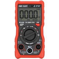
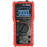
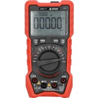
The multifunction meter is a digital measuring instrument designed to measure various electrical quantities.
Before using the meter, read the instruction manual in its entirety and keep it for later use.
The meter features a plastic casing, liquid crystal display, and a measuring range switch. The casing is fitted with measuring sockets and a socket for transistor testing. The meter is fitted with measuring cables terminated with plugs and a stand for testing transistors and small electronic components. The meter is sold without a battery.
CAUTION! This meter is not a measuring instrument within the meaning of the Trade Metrology Act.
TECHNICAL DATA
Display: 4 digit LCD – maximum displayed result: 6000
Sampling frequency: 3 samples/sec
Overload symbol: an "OL" symbol displayed
Polarity symbol: a “—” sign displayed before the result
Battery: 2 x AAA; 3V
Working temperature range: 0 to 40°C at relative air humidity <75%
Storage temperature: -10°C, to +50 °C at relative air humidity <80%
Outer dimensions: 130 × 65 × 32 mm
Weight (without batteries): 114 g
CAUTION! It is forbidden to measure electrical values exceeding the maximum measuring range of the meter.
| Constant voltage ( R_IN = 10 MΩ) | ||
| Range Resolution Accuracy | ||
| 60 mV 0.01 mV | ± (0.5% + 3) | |
| 600 mV 0.1 mV | ||
| 6 V 0.001 V | ||
| 60 V 0.01 V | ||
| 600 V 0.1 mV | ||
| 1000 V 1 V | ||
| Alternating voltage ( R_IN = 10 MΩ; @600 mV > 60 MΩ; f_IN = 40 Hz - 1 kHz) | ||
| Range Resolution Accuracy | ||
| 60 mV 0.01 mV | ± (1.0% + 3) | |
| 600 mV 0.1 mV | ||
| 6 V 0.001 V | ||
| 60 V 0.01 V | ||
| 600 V 0.1 mV | ||
| 750 V 1 V | ||
EN
| Direct current Alternating current (f) | IN=40 Hz - 1 kHz) | ||||
| Range Res | solution Accuracy Range | Resolution Accuracy | |||
| 60 mA 0.01 | 1 mA | ±(1.2% + 3) | 60 mA 0.01 mA | ±(1.5% + 3) | |
| 600 mA 0.1 | mA 600 mA 0.1 mA | ||||
| 6 A 0.001 | A 6 A 0.001 A | ||||
| 10 A 0.01 | A 10 A 0.01 A | ||||
| Resistance | ||
| Range Resolution Accuracy | ||
| 600 Ω 0.1 Ω | ±(0.5% + 3) | |
| 6 kΩ | 0.001 kΩ | |
| 60 kΩ | 0.01 kΩ | |
| 600 kΩ | 0.1 kΩ | |
| 6 MΩ | 0.001 MΩ | |
| 60 MΩ | 0.01 MΩ | ±(1.5% + 3) |
| Capacitance | Frequency | |||
| Range | Resolution | Accuracy | Range | Accuracy |
| 9.999 nF | 0.001 nF | ±(5.0% + 20) | 0 – 9.999 MHz | ±(0.1% + 2) |
| 99.99 nF | 0.01 nF | ±(2.0% + 5) | ||
| 999.9 nF | 0.1 nF | |||
| 9.999 μF | 0.001 μF | |||
| 99.99 μF | 0.01 μF | |||
| 999.9 μF | 0.1 μF | |||
| 9.999 mF | 0.001 mF | ±(5.0% + 5) | ||
| Duty cycle | ||
| Range Resolution Accuracy | ||
| 1% ÷ 99% | 0.1% | ± (0.1% + 2) |
Accuracy: ± % of the indication + weight of the least significant digit
OPERATION
CAUTION! Before opening the casing, disconnect the measuring cables and switch off the meter, to avoid the risk of electric shock.
Safety instructions
Do not operate the meter in an atmosphere with excessive humidity or in the presence of toxic or flammable vapours, or in an explosive atmosphere. Before each use, check the condition of the meter and the measuring cables. If you notice any faults, do not start operation. Replace damaged cables with new ones, devoid of defects. If in doubt, contact the manufacturer. During measurement, hold the measuring cables should by the insulated sections. Do not touch the measurement points or unused measuring sockets of the meter. Disconnect the measuring cables before changing the measured quantity. Never carry out maintenance work without ensuring that the measuring cables have been disconnected from the meter and that the meter itself has been switched off.
Replacing the battery
The multimeter requires batteries, the number and type of which are defined in the technical data
EN
section. It is recommended to use alkaline batteries. To install a battery, open the instrument casing or the battery compartment cover on the underside of the meter. Before accessing the battery compartment, it may be necessary to remove the cover on the meter casing. Connect the battery, according to its terminal marking, close the casing or battery compartment cover. If a battery symbol appears on the screen, the battery must be changed. It is recommended to replace the battery as soon as possible, after the battery symbol appears, to ensure measurement accuracy.
Fuse replacement
The device uses a fast-acting safety fuse. In case of damage, replace the fuse with a new one with identical electrical parameters. To do so, open the meter's casing, following the same procedure as for battery replacement and the safety rules, and change the fuse to a new one.
Switching the meter on and off
Set the measurement switch to the OFF position to turn the meter off. The remaining switch positions activate the meter and make it possible to select the measured quantity and its range. The meter will turn off automatically, if not in use. After about 15 minutes of inactivity, the meter will automatically turn off. This will reduce battery consumption. The user will be notified by an audible signal, approximately one minute before the power supply is turned off.
The SEL/HOLD button
The button is used to manually select the measured value for set points defined by more than one measuring symbol. If pressed and held for approximately 2 seconds, the button will keep the value currently displayed on the screen. In this case, a HOLD symbol appears on the screen.
The RANGE/\* button
The button is used to manually change the measuring range for a given quantity. When pressed, the AUTO symbol will disappear. Pressing the button again will switch the range in the order shown in the table.
To exit the manual range selection, move the selector to a different field, and then return to the previous one. Keeping the button pressed for approx. 2 seconds will activate backlight for the display. Press the button again and hold it for approx. 2 seconds to turn off the display's backlight.
Connecting measuring cables
If the measuring cable plugs are capped, remove the caps before plugging the measuring cables to the sockets. Connect the measuring cables, in accordance with the instructions provided in the manual. Next, remove the caps (if any) on the measuring section and proceed with the measurements.
Built-in buzzer
The meter has a built-in buzzer that beeps briefly each time the selector is moved or a button is pressed to confirm the action has taken place. The buzzer will emit several beeps per minute before the meter is automatically switched off and one long beep immediately before it is automatically switched off. The meter switches off automatically 15 minutes after the last pressing of the button or a change in the selector's position.
MEASUREMENT PROCEDURE
Depending on the current position of the range switch, the display will show three digits. If the battery needs to be replaced, the multimeter indicates this by showing the battery symbol on the display. If the sign “−” appears on the display before the measured value, it means that it has a reversed polarity relative to the meter's connection. If an overload symbol appears on the display, it means that the measuring range has been exceeded and the measuring range must be changed to a higher one.
In the case of measurements of unknown values the meter should be set to the AUTO mode, in which case it determines the best measuring range by itself. If the selector is set to measure AC current or voltage, the meter will start measuring in the True RMS mode. This means that the real effective value of the alternating wave will be measured. If a non-sine wave is measured, the
EN
actual RMS value for that particular wave will be displayed. Special care should be taken when measuring quantities within the highest voltage range, in order to avoid electric shock.
CAUTION! Never allow the measuring range of the meter to be smaller than the measured value. This can damage the meter and cause electric shock.
The correct connection of the cables:
The red cable is connected to the socket marked as V Hz or A mA.
The black cable goes in the jack marked COM.
In order to achieve the highest possible measurement accuracy, optimal measurement conditions should be ensured. The ambient working temperature should be in the range from 18 to 28°C and relative air humidity <75%.
An example of measuring accuracy
Accuracy: ±(% of the indication + weight of the least significant digit)
Measurement of constant voltage: 1.396 V
Accuracy: ±(0.8% + 5)
Calculation of error: 1.396 × 0.8% + 5 × 0.001 = 0.011168 + 0.005 = 0.016168
Measurement result: 1.396 V ± 0.016 V
Voltage measurement
Connect the measuring cables to the sockets marked as V Hz and COM. Set the range switch to the DC or AC voltage measurement position. Connect the measuring cables in parallel to an electrical circuit and read the resultant voltage. Never measure a voltage which is higher than the maximum measuring range. This can damage the meter and cause electric shock.
Current measurement
Depending on the expected measured current intensity, connect the measuring cables to the V Hz and COM sockets, or to the A mA and COM sockets. Select the appropriate measuring range using the knob. The maximum current intensity measured at the V Hz socket can be 999.9 A. If the measured current intensity exceeds 999.9 A, connect the cable to the A mA socket. The maximum current intensity measured at the A mA socket can be 9.999 A, but the measuring time regarding currents exceeding 2 A cannot go beyond 15 seconds. Then, apply at least a 15-minute break before conducting a successive measurement. The V Hz socket can be loaded with a maximum current of 999.9 A, without any time limits. It is forbidden to exceed the maximum values of currents and voltages for a given jack. The measuring cables should be connected in series to the tested electrical circuit. Select the type of current measured, using the selector and read the measurement result. The meter will automatically select the appropriate measuring range, which can be changed by pressing the RANGE button, if necessary.
Caution! Do not exceed the voltage of 36 V DC or 25 V AC, when measuring currents.
Resistance measurement
Connect the measuring cables to the sockets marked as V Hz and COM and set the range switch to the resistance measurement position marked with the symbol. Use the SEL button to select the resistance measurement and the “ ” symbol will appear on the screen. Apply the measuring cables to the terminals of the measured element and read the measurement result. In order to obtain more accurate measurement results, change the measuring range if necessary. It is absolutely forbidden to measure the resistance of elements through which electric current is flowing. For measurements greater than 1 M , the measurement may take a few seconds before the readout becomes stable, which is the normal response for high resistance measurements.
Before applying the tips to the terminals of the measured element, an overload symbol is shown on the display.
Capacitance measurement
Connect the measuring cables to the sockets marked as V Hz and COM and set the range
EN
switch to the capacitance measurement position. Make sure that the capacitor has been discharged, before the measurement. Never measure the capacitance of a charged capacitor as this can damage the meter and cause electric shock. When measuring high-capacitance capacitors, the measurement may take about 30 seconds before the result becomes stable.
When measuring small capacitances, subtract the capacitance of the meter and the measuring cables, to obtain a more accurate result.
Diode test
Connect the measuring cables to the jacks marked "INPUT" and "COM" and set the knob to the diode symbol. Now connect the measuring terminals to the diode leads, according to the direction of conduction and in the reverse direction. If the diode is working, it will show a voltage drop in its forward direction expressed in mV. If connected in the reverse direction, the display will show the overload symbol. Working diodes are characterized by a low resistance in the forward direction and a high resistance in the reverse direction. It is absolutely forbidden to test diodes through which electric current is flowing.
Conductivity test
Connect the measuring cables to the sockets marked as V Hz and COM. Set the selector to the buzzer symbol. If the meter is used to measure conduction, the built-in buzzer will sound whenever the measured resistance drops below 50 . The buzzer can also emit a sound when the resistance is in the range from 50 to 100 . It is absolutely forbidden to test conductivity in circuits through which electric current is flowing.
Frequency measurement
Connect the measuring cables to the sockets marked as V Hz and COM. Select the frequency measurement option with the FUNC button. The display will show the “Hz” symbol. Read the measurement result on the display.
Measurement of the duty cycle
Connect the measuring cables to the sockets marked as V Hz and COM. Set the meter's selector to the “%” position. Use the SEL button to select the filling factor measurement and the “%” symbol will appear on the screen. Read the measurement result on the display.
MAINTENANCE AND STORAGE
Wipe the meter with a soft cloth. Larger amounts of dirt should be removed with a slightly damp cloth. Do not immerse the product in water or any other liquid. Do not use solvents, corrosive or abrasive agents for cleaning. Care should be taken to keep the contacts of the meter and the measuring cables clean. Clean the contacts of the measuring cables with a cloth slightly soaked in isopropyl alcohol. In order to clean the contacts of the meter, turn off the meter and remove the battery. Turn the meter over and shake it gently so that larger pieces of dirt fall out of the meter connectors. Lightly soak a cotton stick with isopropyl alcohol and clean each contact. Wait for the alcohol to evaporate and then install the battery. The meter should be stored in a dry room, inside the supplied unit packaging.