
ERT1400RV - Router RYOBI - Free user manual and instructions
Find the device manual for free ERT1400RV RYOBI in PDF.



User questions about ERT1400RV RYOBI
0 question about this device. Answer the ones you know or ask your own.
Ask a new question about this device
Download the instructions for your Router in PDF format for free! Find your manual ERT1400RV - RYOBI and take your electronic device back in hand. On this page are published all the documents necessary for the use of your device. ERT1400RV by RYOBI.
USER MANUAL ERT1400RV RYOBI
- Speed selection sight window
- Variable speed control selector
- Handle
- Lock-off button
- Spindle lock button
- Parallel guide lock knob
- Chip shield
- Depth stop
- Stop bar
- Stop bar lock knob
- Zero reset indicator
- Scale
- Power cord
- Plunge lock lever quick release button
- Switch
- Router base
- Sub-base
- Spanner
- Parallel guide
- Collet nut
- Threaded post
- Collet
23.Workpiece - Dust port
- Depth of cut
- Width of cut
- First pass
- Second pass
- Fine height adjuster knob
- Fine height adjuster quick release button
- Live tool indicator
- Template guide
- Screw
- Nut
SPECIAL SAFETY RULES
Hold tool by insulated gripping surfaces when performing an operation where the cutting tool may contact hidden wiring or its cord. Contact with a "live" wire will make exposed metal parts of the tool "live" and shock the operator.
- Know your power tool. Read the operator's manual carefully. Learn its applications and limitations, as well as the specific potential hazards related to this tool. Following this rule will reduce the risk of electric shock, fire, or serious injury.
Always wear safety glasses. Everyday eyeglasses have only impact-resistant lenses; they are NOT safety glasses. Following this rule will reduce the risk of serious personal injury.
- Protect your lungs. Wear a face or dust mask if the operation is dusty. Following this rule will reduce the risk of serious personal injury.
- Protect your hearing. Wear hearing protection during extended periods of operation. Following this rule will reduce the risk of serious personal injury.
Inspect tool cords periodically and, if damaged, have repaired at your nearest Factory Service Center or other Authorized Service Organization. - Constantly stay aware of cord location. Following this rule will reduce the risk of electric shock or fire.
- Check damaged parts. Before further use of the tool, a guard or other part that is damaged should be carefully checked to determine that it will operate properly and perform its intended function. Check for alignment of moving parts, binding of moving parts, breakage of parts, mounting, and any other conditions that may affect its operation. A guard or other part that is damaged should be properly repaired or replaced by an authorized service center. Following this rule will reduce the risk of shock, fire, or serious injury.
- Do not abuse cord. Never carry the tool by the cord or yank it to disconnect it from the receptacle. Keep cord away from heat, oil, and sharp edges. Following this rule will reduce the risk of electric shock or fire.
Inspect for and remove all nails from lumber before routing. Following this rule will reduce the risk of serious personal injury. - Do not operate tool while under the influence of drugs, alcohol, or any medication. Following this rule will reduce the risk of electric shock, fire, or serious personal injury.
- Save these instructions. Refer to them frequently and use them to instruct others who may use this tool. If you loan someone this tool, loan them these instructions also.
WARNING
Some dust created by power sanding, sawing, grinding, drilling, and other construction activities contains chemicals known to cause cancer, birth defects or other reproductive harm.
Some examples of these chemicals are:
- lead from lead-based paints
crystalline silica from bricks and cement and other masonry products - arsenic and chromium from chemically-treated lumber
Your risk from these exposures varies, depending on how often you do this type of work. To reduce your exposure to these chemicals, work in a well ventilated area, and work with approved safety equipment, such as those dust masks that are specially designed to filter out microscopic particles.
English
SPECIFICATIONS
| Voltage | 230 V - 240 V ~ 50 Hz |
| No-load speed | 14000-31500 min-1 |
| Input power | 1400 W |
| Plunge depth | 55 mm |
| Collet size | 1/4 in or 6 mm or 8 mm |
| Net weight | 4.3 kg |
APPLICATIONS
Use your router only for the purposes listed below:
- routing grooves, shaping edges, freehand designs, etc., in wood
- chamfering, rabbeting, dadoing, and dovetailing in wood
- routing edges on laminates
FEATURES
Your plunge router is a versatile woodworking tool that will give you years of trouble-free performance. It is engineered with the professional in mind, but its ease of operation allows the amateur to produce work that is beautiful and precise. As the name implies, your plunge router can be used for making plunge cuts in workpieces, routing grooves, edge routing, routing circles, and freehand routing.
When used with recommended accessories, such as a router table, depth adjustment knob, and straight guide, it becomes even more versatile. Various types of cutters, both with and without roller bearings as guides, also add to the versatility of this tool.
CHIP SHIELD
A plastic chip shield has been provided on the base of your router for protection against flying dust and chips. It is designed to fit the front opening of the router base.
SPINDLE LOCK
The spindle lock secures the spindle so that only one wrench is needed to loosen collet nut and change cutters. To operate push the button whilst loosening the collet.
NOTE: Do not run router with spindle lock engaged or use as a brake to stop the router.
VARIABLE SPEED
Your router has advanced electronic features, designed to assist you in getting the maximum use from your router. By making proper speed selections, your tool can be adjusted to specific routing needs.
The electronic feature of your tool introduces the flexibility of adjusting the motor speed to required job conditions. An
electronic speed control module senses the load applied to the motor and increases or decreases motor voltage to compensate for and maintain desired RPM. Speed can be set according to the approximate cutter diameter you will be using and to the hardness of the material being cut. The best cuts are made when the cutter is fed through material at the proper rate of feed.
Plunge lock lever shown after extended wear
See Figure 15.
Plunge lock lever shown in original locked position
See Figure 16.
TEMPLATE GUIDE
See Figure 17.
The template guide can be fitted to the base of the router to accurately duplicate curves and other complex shapes. These shapes can be easily made by using a jigsaw to cut out a template. Fix the guide to the base of the router by removing the two screws retaining the dust extraction port, placing the guide in the recess provided in the base and replacing the screws. The dust extraction port must be in place when fitting the guide to hold the screws.
The guide protrudes below the bottom of the base allowing the router to follow the template, which must be securely fixed to the workpiece and a firm pressure applied to the router at all times to ensure that the edge of the guide accurately follows the template.
The template must be at least 5mm thick to allow for the protrusion of the guide. Allowance must also be made in the template for the distance between the cutting edge of the bit and the outside edge of the template guide.
ERGONOMIC DESIGN
The design of this tool provides for easy handling; it is designed for comfort and ease of grasp when operating in different positions and at different angles.
ELECTRICAL CONNECTION
Your router has a precision built electric motor. It should only be connected to a power supply of the type specified on the rating plate of the machine, AC only. Do not operate this tool on direct current (DC). A voltage drop of more than 10 percent will cause a loss of power and overheating.
If your tool does not operate when plugged into an outlet, double-check the power supply.
DOUBLE INSULATION
Double insulation is a concept in safety in electric power tools, which eliminates the need for the usual three-wire grounded power cord. All exposed metal parts are isolated from the internal metal motor components with protecting
English
insulation. Double insulated tools do not need to be grounded.
WARNING
The double insulated system is intended to protect the user from shock resulting from a break in the tools internal wiring. Observe all normal safety precautions to avoid electrical shock.
IMPORTANT
Servicing of a tool with double insulation requires extreme care and knowledge of the system and should be performed only by a qualified service technician. For service, we suggest you return the tool to your nearest authorized service center for repair.
A WARNING
Do not attempt to modify this tool or create accessories not recommended for use with this tool. Any such alteration or modification is misuse and could result in a hazardous condition leading to possible serious personal injury.
ADJUSTMENTS
WARNING
Your router should never be connected to power supply when you are assembling parts, making adjustments, installing or removing cutters, or when not in use. Disconnecting the tool will prevent accidental starting that could cause serious injury.
CUTTER INSTALLATION
See Figure 3-4.
- Unplug the tool.
WARNING
Failure to unplug the tool could result in accidental starting causing possible serious injury.
CAUTION
To prevent damage to the spindle or spindle lock, always allow motor to come to a complete stop before engaging the spindle lock.
-
Remove chip shield from router base.
-
Depress spindle lock.
- Lay router down on workbench in order to gain easy access to collet nut.
- Place the spanner provided through front of router base onto collet nut and turn counterclockwise to loosen.
WARNING
If you are changing a cutter immediately after use, be careful not to touch the cutter or collet with your hands or fingers. They will get burned because of the heat buildup from cutting. Always use the wrench provided.
- Install cutter once collet nut is loose. If changing cutters, cutter will easily slip from collet after loosening collet nut.
- Insert shank of cutter until shank bottoms out, then pull it out 1/16 in (1.6 mm) to allow for expansion when the bit gets hot.
- Tighten the collet nut.
- Release spindle lock.
- Replace chip shield.
WARNING
If the collet nut is not securely tightened, the cutter may detach during use causing serious personal injury.
WARNING
Do not use cutters with undersized shanks. Undersized shanks will not tighten properly and could be thrown from the tool causing injury.
WARNING
Do not use cutters that are larger in diameter than the opening in router base. Use of such cutters will come in contact with the router base and damage both the cutter and router base. This situation could also cause possible loss of control or create other hazardous conditions that could cause possible serious personal injury.
DEPTH OF CUT
When routing a groove that is too deep to safely cut in one pass, it is best to make the cut in several passes.
Proper depth of cut depends on several factors such as horsepower of the router motor, type of cutter being used and the type of wood being routed. A lightweight, low horsepower router is designed for making shallow cuts.
A router with high horsepower rating can safely cut deeper.
English
Cuts can be made deeper in soft woods, such as white pine, than in tough hardwoods, like oak or maple. Based upon these considerations, choose a depth of cut that will not place excessive strain on router motor. If you find that extra force is needed or that the motor speed slows down considerably, turn off router and reduce the depth of cut.
Then, make the cut in two or more passes.
TO ADJUST DEPTH OF CUT
See Figure 5-7.
- Loosen the stop bar.
- Unlock the plunge lock lever by turning it counter clockwise.
- Lower the router body until the cutter is in contact with the workpiece.
- Lock the depth stop at the right height.
- Set the exact depth of cut using the graduation. The distance between the stop bar and screw of the depth stop is setting plunge depth.
- Tighten the stop bar lock knob to set depth of plunge.
DEPTH STOP
See Figure 8 - 9.
- The depth stop can be used to set three different depths; this is particularly useful for deep cut, performed in steps.
If required, set all three screws.
VARIABLE SPEED CONTROL SELECTOR
See Figure 10.
Your router has a variable speed control selector designed to allow operator control of speed and torque limits. You can make speed selections best suited to the type of cut, the material being cut, and the size of bit being used.
The variable speed control selector allows you to adjust router speed from 14,000 to 31,500min^-1 . To increase the speed and torque of your router, turn the variable speed control selector to a higher setting. Turn to a lower setting to decrease speed and torque.
NOTE: If you do not want to use the variable speed control selector, turn it to the highest possible setting, and the feature will not be active.
We suggest that you practice with the variable speed feature of your router before installing a cutter and making cuts in wood.
ZERO RESET INDICATOR
The zero reset indicator allows you to use the scale provided on the housing to make quick depth of cut changes to existing depth of cut settings. Choose a reference point on the scale and slide the zero reset indicator up or down the scale the distance required
for new depth of cut. Then change stop bar position by loosening lock knob and adjusting stop bar until red line on zero reset indicator moves back to reference point. Tighten the lock knob securely to lock stop bar in new position. The cutter position will now increase or decrease the exact distance the stop bar was adjusted.
OPERATION
SWITCH
See Figure 11.
To turn the router on, press the lock-off button and squeeze the switch. To turn the router off, release both the switch and lock-off button.
CAUTION
We suggest that you practice with your router before installing a cutter and making cuts in wood.
ROUTING
For ease of operation and maintaining proper control, your router has two handles, one on each side of the router base. When using your router hold it firmly with both hands.
Before starting the router, unplug it and make sure the cutter is securely tightened in collet nut and that depth of cut is properly set.
Plug router into power supply, turn it on, and let motor build to its full speed, then gradually plunge or feed cutter into workpiece. Do not let the cutter contact workpiece before turning on router and allowing it to develop full speed.
ROUTING GROOVES
When routing across the face of boards, set router at desired depth of cut, place the edge of router base against workpiece, and turn on the router. Slowly feed the cutter into the workpiece along desired line of cut.
WARNING
If desired depth of cut is greater than can be safely cut in one pass, make cuts in two or more passes.
When routing straight cuts across stock, clamp a straight-edge to the workpiece to use as a guide. Position the straight-edge parallel to the line of cut and offset the distance between the cutting edge of the cutter and the edge of the router base. Hold the router base against the straight-edge and rout the groove.
When routing a groove wider than the diameter of the cutter, clamp a straightedge on both sides of the cutlines.
English
Position both guides parallel to the desired line of cut and spaced equal distances from the desired edges of the groove. Rout along one guide, then reverse direction and rout along the other guide. Clean out any remaining waste in the center of the groove freehand.
FITTING AND ADJUSTING THE PARALLEL GUIDE
See Figure 12.
- Insert the parallel guide into the hole of the router base.
- Draw a cutting line on the workpiece.
- Lower the router body until the cutter is in contact with the workpiece.
- Position the router on the cutting line. The outer cutting edge of the cutter must coincide with the cutting line.
- Without moving the router, push the guide to the edge of the workpiece before tightening the lock knob.
ROUTING BY FREEHAND
When used freehand, your plunge router becomes a flexible and versatile tool. This flexibility makes it possible to easily rout signs, relief sculptures, etc.. There are two basic techniques for freehand routing:
- Routing letters, grooves, and patterns into wood.
- Routing out the background, leaving the letters or pattern raised above the surface.
When freehand routing, we suggest the following:
- Draw or layout the pattern on workpiece.
- Choose the appropriate cutter.
NOTE: A core box or V-groove bit is often used for routing letters and engraving objects. Straight bits and ball mills are often used to make relief carvings. Veining bits are used to carve small, intricate details.
- Rout the pattern in two or more passes. Make the first pass at 25% of the desired depth of cut. This process will provide better control as well as being a guide for the next pass.
- Do not rout deeper than 1/8 in (3.2mm) per pass or cut.
Follow these directions when routing by freehand:
- Choose the appropriate cutter, set desired depth of cut, carefully check set-up, and secure workpiece.
- Make a test cut in a scrap piece of wood from the same workpiece if possible.
- Unlock plunge lock lever to raise cutter from any preset depth of cut. This also permits raising cutter inside router base.
- Place router on workpiece inside pattern to be routed.
-
Grasp handles securely and press the switch to start your router.
-
Let motor build to full speed, then gradually plunge cutter into workpiece until stop bar comes into contact with depth stop.
- Lock plunge lock lever to secure depth of cut setting.
- Begin routing out the pattern, continuing until a complete pass at this depth of cut has been made.
WARNING
Do not use large router bits for freehand routing. Use of large router bits when freehand routing could cause loss of control or create other hazardous conditions that could cause possible serious personal injury.
- Several cuts that require repositioning of router may be needed for a particular job. If this situation exists, unlock plunge lock lever to raise cutter inside router base after each cut, reposition router for next cut, gradually plunge cutter into workpiece until stop bar contacts depth stop, lock plunge lock lever and continue routing.
- After all cuts have been made, unlock plunge lock lever, raise cutter inside router base, remove router from workpiece, turn off the router, and allow cutter to come to a complete stop.
ROUTING EDGES
Place router on workpiece, making sure the router bit does not contact workpiece. Turn router on and let the motor build to its full speed. Begin your cut, gradually feeding cutter into workpiece.
WARNING
Keep a firm grip on router with both hands at all times. Failure to do so could result in loss of control leading to possible serious injury.
Upon completion of cut, turn motor off and let it come to a complete stop before removing router from work surface.
WARNING
Never pull router out of work and place upside down on work surface before the cutter stops.
CONNECTING A DUST EXTRACTOR
See Figure 13.
The dust extractor hose can be connected to the dust extraction channel.
English
FINEHEIGHTADJUSTER
It is used to precisely control the depth of the cutter.
- To use the fine height adjuster, ensure that the plunge lock is released.
- Rotate the knob clockwise to raise the cutter, anticlockwise to lower the cutter.
- When the desired position is reached, re-engage the plunge lock before use.
FINEHEIGHTADJUSTERQUICKRELEASEBUTTON
This disengages the fine height adjuster allowing large adjustments of plunge depth to be quickly made.
- To make large adjustments to cutter height, ensure that the plunge lock is released.
- Press the quick release button whilst plunging the router to the required height.
- Release the button, check the height, make fine adjustments if necessary with the fine height adjuster, then re-engage the plunge lock before use.
DEPTH OF CUT
As previously mentioned, the depth of cut is important because it affects the rate of feed that, in turn, affects the quality of the cut (and, also, the possibility of damage to your router motor and bit). A deep cut requires a slower feed than a shallow one, and a too deep cut will cause you to slow the feed so much that the bit is no longer cutting, it is scraping, instead.
Making a deep cut is never advisable. The smaller bits are easily broken off when subjected to too much side thrust. A large enough bit may not be broken, but if the cut is too deep, a rough cut will result, and it may be very difficult to guide and control the bit as desired. For these reasons, we recommend that you do not exceed 1/8 in (3.2 mm) depth of cut in a single pass, regardless of the bit size or the softness or condition of the workpiece.
To make deeper cuts it is therefore necessary to make as many successive passes as required, lowering the bit 1/8 in (3.2mm) for each new pass. In order to save time, do all the cutting necessary at one depth setting, before lowering the bit for the next pass. This will also assure a uniform depth when the final pass is completed.
LIVE TOOL INDICATOR
This tool features a live tool indicator which illuminates as soon as the tool is connected to the supply. This warns the user that the tool is connected and will operate when the switch is pressed.
MAINTENANCE
WARNING
When servicing, use only identical replacement parts. Use of any other parts may create a hazard or cause product damage.
GENERAL
Avoid using solvents when cleaning plastic parts. Most plastics are susceptible to damage from various types of commercial solvents. Use clean cloths to remove dirt, carbon dust, etc.
WARNING
Do not at any time let brake fluids, gasoline, petroleum-based products, penetrating oils, etc., come in contact with plastic parts. They contain chemicals that can damage, weaken or destroy plastic.
Electric tools used on fiberglass material, wallboard, spackling compounds, or plaster are subject to accelerated wear and possible premature failure because the fiberglass chips and grindings are highly abrasive to bearings, brushes, commutators, etc.. Consequently, we do not recommended that this tool be used for extended work on these types of materials. If, however, you do work with any of these materials, it is extremely important that you clean the tool frequently by blowing it with an air jet.
WARNING
Always wear safety goggles or safety glasses with side shields during power tool operation or when blowing dust. If operation is dusty, also wear a dust mask.
LUBRICATION
All of the bearings in this tool are lubricated with a sufficient amount of high grade lubricant for the life of the unit under normal operating conditions. Therefore, no further lubrication is required.
CUTTERS
Get faster and more accurate cutting results by keeping cutters clean and sharp. Remove all accumulated pitch and gum from cutters after each use.
When sharpening cutters, sharpen only the inside of the cutting edge. Never grind the outside diameter. Be sure when sharpening the end of a cutter to grind the clearance angle the same as originally ground.
English
COLLET
Dust and chips may collect on the collet from time to time, making it necessary to clean the collet. To do so, remove the collet assembly and wipe it with a clean dry rag.
Clean the taper in the shaft in the same manner. Never immerse the collet or end of the shaft in a solvent or in water. Before replacing the collet assembly, put a drop of motor oil on the inside of the nut, on the threads of the shaft, and on the taper in the shaft. Replace the collet assembly onto the shaft by hand only. Never tighten the collet nut without a bit in the collet. This action could permanently damage the collet.
ENVIRONMENTAL PROTECTION

Recycle raw materials instead of disposing of as waste. The machine, accessories and packaging should be sorted for environmental-friendly recycling.
SYMBOL

Safety Alert
V Volts
Hz Hertz
Alternating Current
W Watts
No No-load speed
min-1 Revolutions or reciprocations per minute

CE Conformity

Double insulation

Wear ear protection

Wear eye protection

Please read the instructions carefully before starting the machine.
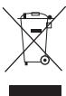
Waste electrical products should not be disposed of with household waste. Please recycle where facilities exist. Check with your Local Authority or retailer for recycling advice.
Français
DESCRIPTION
No permitted in any way, except for the use of a firebox. No permit to bring or carry items from outside the premises. No permits to place on the premises other than those provided by the local authorities.
ALLMÄNNA FÖRESKRIFTER
TEXHUNECKNEXAPAKTEPNUKIN
OBJACTbIPIUMEHEHNA
PIMMEUHAE: Ecnn BbI He xoTne NpIb3OaBtBc8 3eKtPOHHbIM peyIITOPOM CKOpOCTN, NOCTaBte ero Ha cAMyIO BblCCKOY CKOpOCTb.
IpyexJe yem ycTaHabnBaTb ppe3y u ppe3epoBaTb DepeBO npNbIKHNe K 3neKToPHOMy peYJrTOpy.
ДВИЖOK YCTAHOBКHA HOЛь
Двнжok yctahOBkn Ha HONb PONB0JrE TNCNOb3OBAtBuKany Ha Kaptepe Фрета ДяБьстpoс CMeHbI
Pycckn
fpe3epobKn. Bb6epnTe TOky OTCeta Ha
kaane NIOBHHbTe DVBKKO YCTAHOBKn HA HONb BBEpx
HIN BHN3, Tc0bI OH BCTaHa HyxHyIO OTmTKy fynbHb
fpe3epobKn. 3AteM OTnyCTnE pykCy 6NOKnOBKn
fynbHomepa NOTpyeYnnpyIe Ero TAK, Tc0bI KpaCHaA
OTMeTKa Ha DVBKKe BCTaHa NaBb6paHHyIO TOky OTCyTa.
Kpenko 3aTnHnTe pykCy 6NOKnOBKn fynbHomepa,
Tc0bI 3aΦnKcnPOBaTb Ero B 3OM nOLOKeHN. Fpe3a
HaCTpAnBaetcHa NIOXKeHne, OTpyNLpOBaHHoe
fynbHomeopm.
3KCNYATAIIN
BbIKJIIOYATEJIb
CM.puc.11.
YTo6bl 3aIyCTnTb fpe3ep, HAKMNTe Ha KHOIky pa3bLOKIPOBKN KypKa, 3aTeM Ha KypOK. YTo6bl OCTaHOBnTb fpe3ep, OTNyCTne Kypok.
BHIMAHNE
Ipejde yem yctaHaBnBaTb pfpe3y u pfpe3epoBaTb DepeBO npNBkHInTe K pfpe3epy.
ΦPE3EPOBKA
Дя Han60nbIeero yO6c7Ba n KOHTpOra NaHCTpymENTOM φpe3ep OCHaUeH DByM pyKamn no6okam. Пп равote Kpenko DePknte φpe3ep obemnnpykamn.
Ipeed Hauanom pa60tby 6ybadntceb, TTO qpe3ep BbvkIOHc H3 cetTu, TTO qpe3a Hadejxho 3axata B nATPOHn rnybHna qpe3ePOBKn OTperyIipOBaHa.
BkIIOHTe 0pe3ep B ceTb, 3aNyCTte erO n noIOXJNTe, NOKA MOTOP Haepept NOHIOY CCKOPTB, 3aTEM BBOITe 0pe3y B 3aOTOBKY. Pe3za He dONKHa KacaTbC3aOTOBKN, NOKA MOTOP HE BkIOHTCN He Haepept NoHIIx XoD.
BbIbOPKA Ia3OB
Ppi nonepeuHoi Bb6opKe B DoCKax, OtperynnpuyTe
Pfpe3ep Ha HyxHyo Pny6Hy Fppe3epOBKn, NoctabBte
Kpaia CTOna Pfpe3epa K 3arOTobKe N BKIOUHTe Fppe3ep.
MeIJIeHNO BBOJNTe Fpe3y B 3arOTOBky N haMeueHHo
JIINHM.
A OCTOPOXHO
EcnIpybHaΦpe3epOBKn CnIIKOM 6OJIbSAa I ee HEnb3I PpOn3BcETN B OINH pOxO,I, BblpaTte 3aROTBky B HECKoJIbKO pOxOIOB.
Ipn npmao fpe3epOBke B DepeBe, npnKpEnIte Ctpy6uHno IInHeKy K 3arotobke. PacnoJoxKeIte 3aroTobky napalneBHO IINnnppe3epOBKn OtperyLpyuPcTacToHNe MmJy peJyUm Kpaem fpe3bl n Kpaem cToNa. PnKImaTe cToI ppe3epa K IInHeKe N haHnHaTe Bb6Opky.
Ecnn Bv6Opka 7npe DnaMetpa fpe3bl, pnpKpEnIte cTpy6cHNOH DBe LInHeNKn PO oBe cTOpObI LInHN Ppe3epOBKn.
IIOJOKNTe IINHeIKn npaIIeJIbHO IINHn HpE3epOBKn Ha OINHAKOBOM paccToHNN OT KPAEB HAMEUEHNO BblOpKn. FpE3epyTe BnpeD BOnb ONDH IINHeKN, a o6paTHbI npOxOd DeaIte BOnb DpyroY. YdaJIaTNe CTpyKky N3 BblOpKn.
YCTAHOBKA IN PERGYIINPOBKA IAPAJIIIEbHOH HANPABJIOUJIEN
CM.puc.12.
- BCTaBte napalneBHyu HnpaBnaIouyU B OTBePCTNBA CToNEΦpe3epa.
- Hauerpntte JINHIO Ope3epOBKn Ha 3aROtOBKe.
- Onyctnte pa6oyn 6Iok, YTO6bl 6pe3a KocHynacb 3aTOTOBKN.
- Поставытpe3ep Ha пинию pe3epoBKM. Bheunn pekyuni kpaJ pe3bIdoJxKeH cTOrTbHa nHHN ppe3epoBKM.
- Празду Рьнокаь Фретер, установпетапалленьнунарравяшук К краю 3агOTбИи 3атгнerte руну 6лOKИРОВКи паллельнйнарравяшец.
ΦPE3EPOBKA HABECY
Ipi npaobote HabeCy fpe3ep ctaHOBNTc yHINBepCaJIbHIM INCHPTyPMENTOM.HaBeCy MOxHO INrOtaBnBaTb fHyprHbIe n peJIbeFhIbe fOpMbI.CyUeCTByET DBe OCHOBHbIe TEXHNKf pfe3epOBKn HabeCy:
-ФрeЗервka 6укВ,Фигуня Вьборka B Деревe;
- pfe3epOBka fOHa, BbIeJIaHuapeIbeΦ 6yKB nIi fIpy.
PnΦpe3epOBKe HABecy nOJIb3yITeCb CNeJyUoUIMN INHCTpyKUaMn:
- Hahecnte pncyHok Ha 3aTOrTOBky.
- BbI6epnTe pOxOJyU Ofpe3y.
INPIMEYAHNE:ДЯфpezeровКБукВигравиорычастОпслльзHTФpe3blДЯТВерстИNKOнчeckneФpe3bl.ПямBLEиСфрчeckneФpe3blчaTOИСлльзHTOTСВВрелбфнOсКУнTType.Фpe3blДЯнHepBOPИСлльзHTOTСДггврИровКСLOXKHBIXиМELKINxФФOM.
- Φezepeynte φopMy B Heckonbko npoxoob. B nepBbI npoxoD BbI6epnte 25% HxHcHn ryn6nHbI.
Pycckn
3To nO3B0JNT lyUyIe KOHTpOJInpoBaTb ppe3epoBky I nocnyjNt 7a6NoHOM dIra CNeDyIOxN xPOXoOB.
4. He BbIbIpaIte 6oJIbIe 3,2 MM 3a npoxoI.
PnFpe3epoBKe HabeCy noIb3yITeCb CJeIyUOIMN INCTpyKUAMN:
- Bb6epnre noxodyauyo 3py3y, oTpeynpnyTe rIybuNy pe3a, 3aTe m npOBepBte BCE peryuPobkn i 3akpennte 3arOToBYk.
2.ПоиЗБeДпTe ПббHь Pe3Ha OTxOДх МATEрИАla, JELaTeJIbHO TOI J6 3aTOBKn. - Tc0bI cMeHntb peYInpOBy rny6Bnblpe3a, OtynCTte pIyar bIoknOpOBKn norpkyKeHn. Ppe3a BIXoDITN 3OCHOBAHnpe3epa.
- Поставы сер на заювку и наевпеше сеу на линникpe3a.
- Kpenko Bo3bMITEcb 3a pyuKIn, yTOIINTE KhoNkpya3bOKNIOBPOBN KpKa n HAKMNTE Ha KpOK, YTO6bl3anyCTNTb fpe3ep.
- DaiTe MOTOpy H6paTb NOnHbY XoD IN MeIeNHO nOrpykaite ppe3y 2aToRtOBky, NOKa rIy6nHOMep He DoJdent Do ynpora rIy6nHbY.
- 3aKpoTe pBvag 6nOKpOBKn norgyKeHn, TTo6b3 aΦuKcnpoBaT rIy6hNy.
- HauHaiTe Φpe3epOBky φopMbI Do KOHca npoxoHa 3aDaHHoI rIy6bHe.
OCTOPOXHO
He noIb3yIteCb 6oJIbUHMM Ppe3aMn npi pa6Ote HabeCy. MoXHO nOTepRb KOHTpObl NaH INCTpyMeHToM I Co3aTb OnaChbIE CNTyaCm, BeDyUne K TArKeJbIM TpaBAM.
9.ДЯocobix BINOB Φpe3epOBKIMOKeT notpe6oBaTc npOn3BcTeH HeckOJIbKO npoxoDB pa3HbIM npeyInpOBKaMn. B 3tOM cIyuae OTKpoIte pblar 6nOKpOBKn norpUxHeN, YTObI NOdHMATb fpe3y u3 ochOBaHNCTaHkA NOcNe KaJdOro npoxoJa, 3aTEM NOCTabBe CTAnOH kINr CneDyUoJero npoxoJa, MeNdHNO Norpy3uTE fpe3Y B 3aRTOBKy, Noka rnybInHomep He DoiJeT Do yOpna rnybInHs, 3akpoIte pbIur nOrpyKeHn I npOdoJkaTe fpe3epOBKy.
10. Pocne nocceJeHero npoxOa, oTKpoIe pIyar, NOINMITE pa6OHyn 6IOK, CHNMTe fpe3ep c 3aTOBKN, BbIKNHTe ero nNoDQJNTe, NOKa fpe3a NONHOCTBO He OCTaHOBTTCR.
ПОФИЛПОВАНЕ
YctaHOBInTe paOchn 6bOK ppe3epa Hd 3aROTOBko, YTObbl ppe3a ee He Kacanaeb. 3anyCTIte ppe3epu N daIte MOTOpy HaBaPb tonHb xoJ. MeDJIeHHO norpyxauHe ppey B 3aROTOBky.
A OCTOPOXHO
Bcerda kpenko depekhtte pfeep36 ob6mny pkamn. B npotnbHOM cnyae moKHO nopeTb KOHTpNb Hnd NHCPTPMHTOM nIOnyUHTb TKAJENbIe TPAmbIy.
IIOOKOHaHIN paObTb BblKnHOpHTe pHe3ep N, npExKeYem CHMnBte er c PoacheN noBepxHOCTn, nOdoXdTe, NOKA MOTOP NIOHOCTbIO He OCTaHOBITcR.
A OCTOPOXHO
Hikorga He Chmua Te ppeep c 3a0rTOBkn HnepeBopaunBaIte ero Ha paOheN nobEpxHOCTn noka ppe3o nIOHOCTbO He octaHOBNiAB.
YCTAHOBKA CONJII TbJIIECOCA
CM.puc.13.
CoNLO MOKHO COeHNHTc Tpy6koI nbIeocca.
PYUKAMNKPOMETPNUECKOPEYUN-POBKN
3Ta pyka I03BOJRAET TOHOp epynnpoBaT bBICOTy fpe3bl.
- Tóboblonl30BaTb5cnykoMmKpOMeTpHeeCKoIpeYnIpOBKn,pa36IokuPyTe pbUar 6IokuPbKNnorpUyKeHnna.
- YTo6bI noDnHrTb 0pe3y, noBopauHBAIte pyuKy BnPaBO, a YTo6bI onyCTnTb - BnEBO.
- OTPerynipoBav HuykHyu BbICOTy, 3akpoTepbHar 6IOKIpOBKn nOpyKeHn.
KHONKA PA3BLOKINPOBKN PYUKN MKNPOMETPN-UECKOPEYUNIPOBKNIJYBHNb
3Ta KhoNka no3BoJnE r pa36JoknPoBaTb 6bIcTpOOCBOoDnTb pyKu MmKpOMeTrnHecko peRyIInpoBKN.
- TROblc0b6oDnTb pyChy MmKpOMeTpHecKOIpeYtnIpOBKn,pa3b5nOKnpuTe pbUar IoknPobKn norpUxKeHnA.
- HaxmITE Ha KhoIky pa36bOKIpOBKpyuKIMKpOMeTpUeCKoey peYnIpOBK, OndHOBpeMeHO ONyckar cyNIOPT ha HyxHyO bByCOTy.
- OTnyctnte KhoNky n npoBepbTe BvICOTy.Ipn Heo6xoDnMocTn noCtpoIte dppe3ep pyuKo MmKpOMeTpnuEckOn peYnnpOBkIn 3aKpOte pbUar 6bnKpOBKn norpyuKeHnna.
TJYBUNHAPE3AHNA
Kak yke 6bIIO cKa3aHO BIIe, rIy6HnHa fpe3epoBKN BINIET HA CKOOPCTb pe3a fpe3bl n, CJIeIOBaTEIbHO, HA KaueCTBO pa60bl.ΓIy6HnHa fpe3epoBKN MOKeT NOBpeiHT Mobp I fpe3y. ΓIy6kAa fpe3epoBKA npON3BODNTcra Ma MeIeHNHO CKOpCtN.PnCNIuKOM rIy6KoI Ofpe3epoBKe CKOPOCTb pe3a MOKeT HactOnIbKO
Pycckn
CHN3NTbCRA, YTO Φpe3a 6yIeT He pe3aTb, a KOJOTb 3aROTOBky.
Ipy60kyo pfe3epOBky DeNaTb He pekOMeHdyETcR. ManHeKne pfe3bl NeKo IomAoTcR OT CnBHorO 60koBOrO DabNeHry. NIpOKa pfe3a MoKet BbIepKxTaB rly60kyo BbIbOpKy, HO oHa HE bSyet TcHOn I ee 6yEt TpyDn HnPaBnY I KOHTpOInPobAtb. Po3Tomy peKoMeHdyETcR He bIbNpaTb 60JIbe 3,2 MM 3a OIN npXoD, He3aBmmoTo pa3Mpa Pfe3bl, TBpeDcTn I noNoKeHn 3arOTOBKn.
Длггубokоь ВьБОрки HeOBxODIMO DeNaTb HeCKOnьКo npoxOobИ nocne КадтOrO npoxOda onyckaTbФpe3y H32MM.ТTOБblBnIrpaTbВpeM, npOn3BOuInTe BCE NaCTPovKn rIy6BnHbI Phpe3ePobKN Do TOrO KaK onyCkTaB paOboNb6nOK dЯ nCleDyUHSeIero npoxOda.TorJa nocNe nocSKeIeHrero npoxOda rIy6BnHa Phpe3ePobKN 6ydET ODHOpOdHoi.
XMTb INHДNKATOPOM NHCTPYMEHT
DaHHbI hNCTpyMeHT OCHaUeH INDnKaTOpOM NITAHIN, KOTOBI 3aogapTaECr PnOJDKnIOHeHN INHCTpyMeHTaK cETNI TAHIN. OH npEynPpeJaet, YTO hNCTpyMeHT nOxDKIOUeH N6yEd pa6oTaBn Pn Haxatmbl BkIIIOuOATENaI.
TEXHMHUECKOE OBCJYXMBAHNE
OCTOPOXHO
PnpnoBedeHn TeKyuIepeMOHTa nCNoIb3yIte TOJIbKO IeHTInHbIe 3aNpactN.1cNoJIb3OBAHne JIO6bIX dpyrNX 3aNpacteM MoKeT co3aTaB oAnchOCTb INI CTab npnHNO BixOda N3dEINNA 3tCPor.
OBUJAR INHΦOPMAUJRA
POSEBNA SIGURNOSNA PRAVILA
Alat drzite na izoliranim i protukliznim dijelovima aka radite na podlozi koji bi mogla sakriti elektricne zice. Uvijek upotrebljavaje vodiligare parallelnog piljenja ili ravnu letvu dock obavlmente parallelno rezanje.
- Upoznajte svoj elektrichi na lat. Pazljivo pročitajte upute za uporabu. Saznajte primjenu i ograničença je uredaja kao i odrežne potencjalne opasnosti verzane za ovaj uredaj. Tako Čeće izbjeci opasnost od strujnog udara, požara i teških ozljeda.
Uvijek nosite sigurnosne naoScale. Svakodnevne naoScale imajuismo lece otporne na udar; one nisu sigurnosne naoScale. Tako cete izbeci opasnost od teshikh ozljeda.
Zašitite svoja pluça. Ako se pri korišenju stvara prasina, dobro je da nosite za lice ili masku. Tako cete izbjeci opasnost od tešikh ozljeda.
Zašitite svoj sluh. Tijekom produljenih razdoblja
rada nosite zastitu za sluh. Tako cete izbije opasnost od tešikh ozljeda.
KESIN AYARLAMA CUBUGU
KESIN AYARLAMA CUBUGU KILIT ACMA DÜGMESI
All Ryobi products are guaranteed against manufacturing defects and defective parts for a period of twenty four (24) months from the date stated on the original invoice drawn up by the retailer and given to the end user.
Deterioration caused by normal wear and tear, unauthorised or improper use or maintenance, or overload are excluded from this guarantee as are accessories such as battery packs, light bulbs, blades, fittings, bags, etc. In the event of malfunction during the warranty period, please take the NON-DISMANTLED product, along with the proof of purchase, to your retailer or nearest Authorised Ryobi Service Centre.
This warranty in no way affects your legal rights concerning defective products.
FR
GARANTIE - CONDITIONS
The vibration emission level given in this information sheet has been measured in accordance with a standardised test given in EN 60745 and may be used to compare one tool with another. It may be used for a preliminary assessment of exposure. The declared vibration emission level represents the main applications of the tool. However if the tool is used for different applications, with different accessories or poorly maintained, the vibration emission may differ. This may significantly increase the exposure level over the total working period.
An estimation of the level of exposure to vibration should also take into account the times when the tool is switched off or when it is running but not actually doing the job. This may significantly reduce the exposure level over the total working period. Identify additional safety measures to protect the operator from the effects of vibration such as: maintain the tool and the accessories, keep the hands warm, organisation of work patterns.
FR
AVERTISSEMENT
DECLARATION OF CONFORMITY
We declare under our sole responsibility that this product is in conformity with the following standards or standardized documents: 2006/42/EC, 2006/95/EC, 2004/108/EC, EN55014-1, EN55014-2, EN61000-3-2, EN61000-3-3, EN60745-1, EN60745-2-17, EN50366 Noise level [K = 3dB(A)] .. Lp = 94dB(A) Lw=105dB(A) Vibration level [K = 1.5m / s] . ah = 3.78m / s^2

Déclaration de CONFORMITE
Address: 24/F, CDW BUILDING, 388 CASTLE PEAK ROAD, TSUEN WAN, HONG KONG.
Web: www.ttigroup.com
Name/Title: Brian Ellis / Vice President - Engineering
Signature:

Jul 15, 2010
Technical File at
Name of company: TTI EMEA
Address: MEDINA HOUSE, FIELDHOUSE LANE, MARLOW, BUCKS, SL7 1TB, UNITED KINGDOM.
Web: www.ttigroup.com
Name/Title: Carl A. Jeffries / Head of Ryobi Product Marketing
Signature:

Trademarks:
The use of the trademark Ryobi is pursuant to a license granted by Ryobi Limited.