R161 - Router RYOBI - Free user manual and instructions
Find the device manual for free R161 RYOBI in PDF.
User questions about R161 RYOBI
0 question about this device. Answer the ones you know or ask your own.
Ask a new question about this device
Download the instructions for your Router in PDF format for free! Find your manual R161 - RYOBI and take your electronic device back in hand. On this page are published all the documents necessary for the use of your device. R161 by RYOBI.
USER MANUAL R161 RYOBI
| SPECIFICATIONS: | |
| Depth Of Cut | 0 - 1-1/2 in. (0 - 38.1 mm) |
| Collet | 1/4 in. (6.4 mm) |
| Horsepower | 1-1/2 HP |
| Rating | 120 Volts, 60Hz, AC Only |
| Amperes | 8.0 |
| No Load Speed | 25,000 RPM |
| Net Weight | 7.8 lbs. (3.5 kg) |
THANK YOU FOR BUYING A RYOBI ROUTER.
Your new router has been engineered and manufactured to Ryobi's high standard for dependability, ease of operation, and operator safety. Properly cared for, it will give you years of rugged, trouble-free performance.
CAUTION: Carefully read through this entire operator's manual before using your new router.
Pay close attention to the Rules for Safe Operation,Warnings,and Cautions.If you use your router properly and only for what it is intended, you will enjoy years of safe, reliable service.
Thank you again for buying a Ryobi router.
TABLE OF CONTENTS
Table of Contents and Introduction 2
■ Rules for Safe Operation 3-5
■ Electrical and Unpacking 6
Features 7
Adjustments 8-9
Operation 10-14
■ Maintenance. 14-15
■ Optional Accessories 15
Parts Ordering / Service 16
INTRODUCTION
Your router has many features for making cutting operations more pleasant and enjoyable. Safety, performance, and dependability have been given top priority in the design of this router making it easy to maintain and operate.

CAUTION:
Carefully read through this entire operator's manual before using your new router. Pay close attention to the Rules for Safe Operation and all Safety Alert Symbols including Danger, Warning, and Caution. If you use your router properly and only for what it is intended, you will enjoy years of safe, reliable service.
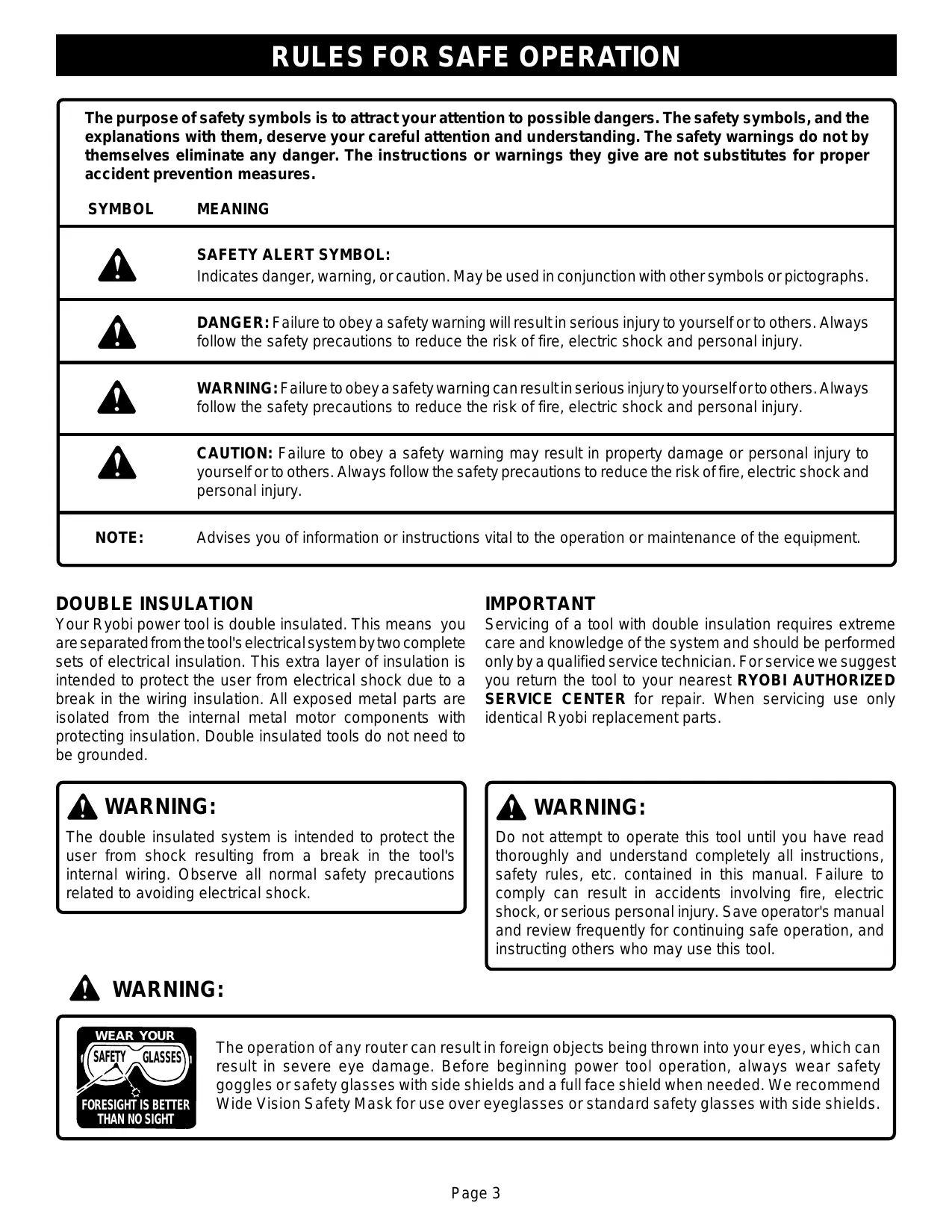
| The purpose of safety symbols is to attract your attention to possible dangers. The safety symbols, and the explanations with them, deserve your careful attention and understanding. The safety warnings do not by themselves eliminate any danger. The instructions or warnings they give are not substitutes for proper accident prevention measures. | |
| SYMBOL | MEANING |
| SAFETY ALERT SYMBOL: Indicates danger, warning, or caution. May be used in conjunction with other symbols or pictographs. | |
| DANGER: Failure to obey a safety warning will result in serious injury to yourself or to others. Always follow the safety precautions to reduce the risk of fire, electric shock and personal injury. | |
| WARNING: Failure to obey a safety warning can result in serious injury to yourself or to others. Always follow the safety precautions to reduce the risk of fire, electric shock and personal injury. | |
| CAUTION: Failure to obey a safety warning may result in property damage or personal injury to yourself or to others. Always follow the safety precautions to reduce the risk of fire, electric shock and personal injury. | |
| NOTE: | Advises you of information or instructions vital to the operation or maintenance of the equipment. |
DOUBLE INSULATION
Your Ryobi power tool is double insulated. This means you are separated from the tool's electrical system by two complete sets of electrical insulation. This extra layer of insulation is intended to protect the user from electrical shock due to a break in the wiring insulation. All exposed metal parts are isolated from the internal metal motor components with protecting insulation. Double insulated tools do not need to be grounded.
IMPORTANT
Servicing of a tool with double insulation requires extreme care and knowledge of the system and should be performed only by a qualified service technician. For service we suggest you return the tool to your nearest RYOBI AUTHORIZATION SERVICE CENTER for repair. When servicing use only identical Ryobi replacement parts.

WARNING:
The double insulated system is intended to protect the user from shock resulting from a break in the tool's internal wiring. Observe all normal safety precautions related to avoiding electrical shock.

WARNING:
Do not attempt to operate this tool until you have read thoroughly and understand completely all instructions, safety rules, etc. contained in this manual. Failure to comply can result in accidents involving fire, electric shock, or serious personal injury. Save operator's manual and review frequently for continuing safe operation, and instructing others who may use this tool.

WARNING:

The operation of any router can result in foreign objects being thrown into your eyes, which can result in severe eye damage. Before beginning power tool operation, always wear safety goggles or safety glasses with side shields and a full face shield when needed. We recommend Wide Vision Safety Mask for use over eyeglasses or standard safety glasses with side shields.
Safe operation of this power tool requires that you read and understand this operator's manual and all labels affixed to the tool. Safety is a combination of common sense, staying alert, and knowing how your router works.
READ ALL INSTRUCTIONS
■ KNOW YOUR POWER TOOL. Read the operator's manual carefully. Learn the applications and limitations as well as specific potential hazards related to this tool.
■ GUARD AGAINST ELECTRICAL SHOCK by preventing body contact with grounded surfaces. For example: pipes, radiators, ranges, refrigerator enclosures.
■ KEEP GUARDS IN PLACE and in working order.
■ REMOVE ADJUSTING KEYS AND WRENCHES. Form habit of checking to see that keys and adjusting wrenches are removed from tool before turning it on.
■ KEEP THE WORK AREA CLEAN. Cluttered areas and work benches invite accidents.
DONT USE IN DANGEROUS ENVIRONMENTS. Do not use power tools near gasoline or other flammable liquids, in damp or wet locations or expose them to rain. Keep work area well lighted.
■ KEEP CHILDREN AND VISITORS AWAY. All visitors should wear safety glasses and be kept a safe distance from work area. Do not let visitors contact tool or extension cord.
■ MAKE WORKSHOP CHILDPROOF with padlocks, master switches, or by removing starter keys.
DONT FORCE THE TOOL. It will do the job better and safer at the rate for which it was designed.
USE THE RIGHT TOOL. Do not force tool or attachment to do a job for which it was not designed. Don't use tool for purpose not intended; for example, a circular saw should never be used for cutting tree limbs or logs.
USE THE PROPER EXTENSION CORD. Make sure your extension cord is in good condition. When using an extension cord, be sure to use one heavy enough to carry the current your product will draw. An undersized cord will cause a drop in line voltage resulting in loss of power and overheating. A wire gauge size (A.W.G.) of at least 14 is recommended for an extension cord 50 feet or less in length. A cord exceeding 50 feet is not recommended. If in doubt, use the next heavier gauge. The smaller the gauge number, the heavier the cord.
■ WEAR PROPER APPAREL. Do not wear loose clothing, neckties, or jewelry that can get caught in tool's moving parts and cause personal injury. Nonslip footwear is recommended when working outdoors. Wear protective hair covering to contain long hair and keep it from being drawn into nearby air vents.
STORE IDLE TOOLS. When not in use, tools should be stored in a high, dry place or locked-up and out of the reach of children.
SECURE WORK. Use clamps or a vise to hold work when practical. It is safer than using your hand and it
frees both hands to operate the tool.
DONT OVERREACH. Keep proper footing and balance at all times. Do not use on a ladder or unstable support.
■ MAINTAIN TOOLS WITH CARE. Keep tools sharp and clean for best and safest performance. Follow instructions for lubricating and changing accessories.
■ DISCONNECT ALL TOOLS. When not in use, before servicing, or when changing attachments, bits, cutters, etc., all tools should be disconnected from power supply.
AVOID ACCIDENTAL STARTING. Don't carry plugged-in tools with finger on switch. Be sure switch is off when plugging in.
USE RECOMMENDED ACCESSORIES. The use of improper accessories may cause risk of injury.
■ CHECK DAMAGED PARTS. Before further use of the tool, a guard or other part that is damaged should be carefully checked to determine that it will operate properly and perform its intended function. Check for alignment of moving parts, binding of moving parts, breakage of parts, mounting and any other conditions that may affect its operation. A guard or other part that is damaged should be properly repaired or replaced by an authorized service center unless indicated elsewhere in this instruction manual.
NEVER LEAVE TOOL RUNNING UNATTENDED. TURN POWER OFF. Disconnect all tools when not in use, before servicing, or when changing attachments, wheels, etc.
DONT ABUSE CORD. Never carry tool by the cord or yank it to disconnect from receptacle. Keep cord from heat, oil, and sharp edges.
PROTECT YOUR LUNGS. Wear a face or dust mask if operation is dusty.
PROTECT YOUR HEARING. Wear hearing protection during extended periods of operation.

WARNING: Cutter coasts after turn off.
■ ALWAYS WEAR SAFETY GLASSES WITH SIDE SHIELDS. Everyday eyeglasses have only impact-resistant lenses; they are NOT safety glasses.
OUTDOOR USE EXTENSION CORDS. When tool is used outdoors, use only extension cords suitable for use outdoors. Outdoor approved cords are marked with the suffix W-A. For example: SJTW-A or SJOW-A.
■ KEEP CUTTERS CLEAN AND SHARP. Sharp cutters minimize stalling and kickback.
■ KEEP HANDS AWAY FROM CUTTING AREA. Keep hands away from cutters. Do not reach underneath work while cutter is rotating. Do not attempt to remove material while cutter is rotating.
NEVER STAND ON TOOL. Serious injury could occur if tool is tipped or if the blade is unintentionally contacted.
NEVER USE IN AN EXPLOSIVE ATMOSPHERE. Normal sparking of the motor could ignite fumes.
INSPECT EXTENSION CORDS PERIODICALLY and replace if damaged.
INSPECT TOOL CORDS PERIODICALLY and if damaged, have repaired at your nearest authorized service center. Stay constantly aware of cord location.
■ KEEP HANDLES DRY, CLEAN, AND FREE FROM OIL AND GREASE. Always use a clean cloth when cleaning. Never use brake fluids, gasoline, petroleum-based products or any strong solvents to clean your tool.
STAY ALERT. Watch what you are doing and use common sense. Do not operate tool when you are tired. Do not rush.
DO NOT USE TOOL IF SWITCH DOES NOT TURN IT ON AND OFF. Have defective switches replaced by an authorized service center.
INSPECT FOR and remove all nails from lumber before routing.
DO NOT OPERATE THIS TOOL WHILE UNDER THE INFLUENCE OF DRUGS, ALCOHOL, OR ANY MEDICATION.

WARNING:
When servicing use only identical Ryobi replacement parts. Use of any other parts may create a hazard or cause product damage.
■ DO NOT USE TOOL UNDER "BROWNOUT" OR OTHER LOW VOLTAGE CONDITIONS. Also, do not use with any device that could cause the power supply voltage to change.
■ POLARIZED PLUGS. To reduce the risk of electric shock, this tool has a polarized plug (one blade is wider than the other). This plug fits in a polarized outlet only one way. If the plug does not fit fully in the outlet, reverse the plug. If it still does not fit, contact a qualified electrician to install the proper outlet. Do not change the plug in any way.
■ WHEN USING THIS ROUTER WITH A ROUTER TABLE, HELP PREVENT POSSIBLE SERIOUS INJURY BY KEEPING THE CUTTER GUARDED AT ALL TIMES. Use only UL listed router tables, with guards, that have been designed for use on routers that are of this type, size, and weight.
SAVE THESE INSTRUCTIONS. Refer to them frequently and use them to instruct other users. If you loan someone this tool, loan them these instructions also.

WARNING:
Some dust created by power sanding, sawing, grinding, drilling, and other construction activities contains chemicals known to cause cancer, birth defects or other reproductive harm. Some examples of these chemicals are:
- lead from lead-based paints,
crystalline silica from bricks and cement and other masonry products, and - arsenic and chromium from chemically-treated lumber.
Your risk from these exposures varies, depending on how often you do this type of work. To reduce your exposure to these chemicals, work in a well ventilated area, and work with approved safety equipment, such as those dust masks that are specially designed to filter out microscopic particles.

SAVE THESE INSTRUCTIONS
ELECTRICAL
EXTENSION CORDS
When using a power tool at a considerable distance from the power source, use an extension cord heavy enough to carry the current that the tool will draw. An undersized extension cord will cause a drop in line voltage, resulting in a loss of power and causing the motor to overheat. Use the chart provided below to determine the minimum wire size required in an extension cord. Only round jacketed cords listed by Underwriter's Laboratories (UL) should be used.
Length of Extension Cord Wire Size (A.W.G.)
Up to 50
14
When working with the tool outdoors, use an extension cord that is designed for outside use. This is indicated by the letters WA on the cord's jacket.
Before using an extension cord, inspect it for loose or exposed wires and cut or worn insulation.
ELECTRICAL CONNECTION
Your router has a precision built electric motor. It should be connected to a power supply that is 120 volts, 60Hz, AC only (normal household current). Do not operate this tool on direct current (DC). A substantial voltage drop will cause loss of power and the motor will overheat. If your tool does not operate when plugged into an outlet, double-check the power supply.
CAUTION:
Keep the cord away from the cutting area and position the cord so that it will not be caught on lumber, tools, or other objects during cutting.
UNPACKING
Your router has been shipped completely assembled and ready for use. Inspect it carefully to make sure no breakage or damage has occurred during shipping. If any parts are damaged or missing, contact your nearest dealer to obtain replacement parts before attempting to operate router. A wrench, operator's manual, and warranty registration are also included.

WARNING:
To prevent accidental starting or electrical shock that could cause possible serious personal injury, assemble all parts to your router before connecting it to power supply. Router should never be connected to power supply when you are assembling parts, making adjustments, lubricating, installing or removing cutters, cleaning, or when not in use.
WARNING:
If any parts are missing, do not operate your router until the missing parts are replaced. Failure to do so could result in possible serious personal injury.
- Carefully lift router from the carton and place it on a level work surface.
- Do not discard the packing materials until you have carefully inspected the router, identified all parts, and satisfactorily operated your new router.
Note: If any parts are damaged or missing, do not attempt to plug in the power cord and turn the switch on until the damaged or missing parts are obtained and are installed correctly.

Look for this symbol to point out important safety precautions. It means attention!!! Your safety is involved.
KNOW YOUR ROUTER
See Figure 1.
Before attempting to use your router, familiarize yourself with all operating features and safety requirements.

WARNING:
Do not allow familiarity with your router to make you careless. Remember that a careless fraction of a second is sufficient to inflict severe injury.
CHIP SHIELD
A clear plastic chip shield is installed on the front of your router for protection against flying dust and chips. The shield is designed to fit the front opening of the router base. See Figure 1. If necessary to remove chip shield, squeeze the tabs on each end and pull outward. To replace, squeeze the tabs at each end, fit into opening, then release.
Note: For your protection, do not use router without chip shield properly in place.

WARNING:
Always wear safety goggles or safety glasses with side shields when operating your router. Failure to do so could result in dust, shavings, loose particles or foreign objects being thrown into your eyes, causing possible serious injury.
LOCK-ON BUTTON
The switch of your router is equipped with a "lock-on" feature which is convenient when operating for extended periods of time. To lock on, depress the trigger, push in the lock button located on the side of the handle, then while holding the lock button pushed in, release the trigger. To release the lock, depress the trigger and release it. See Figure 1.
UPSIDE DOWN VIEW OF ROUTER
Fig. 1
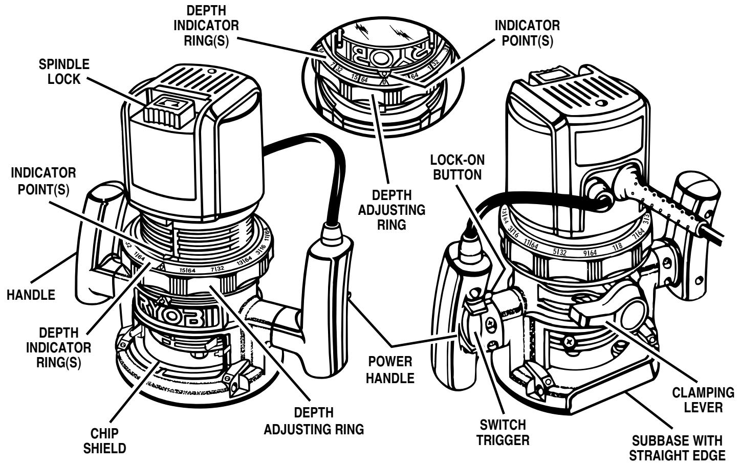
FRONT VIEW OF ROUTER
REAR VIEW OF ROUTER

WARNING:
Your router should never be connected to a power supply when you are assembling parts, making adjustments, installing or removing cutters, or when not in use. Disconnecting your router will prevent accidental starting that could cause serious injury.
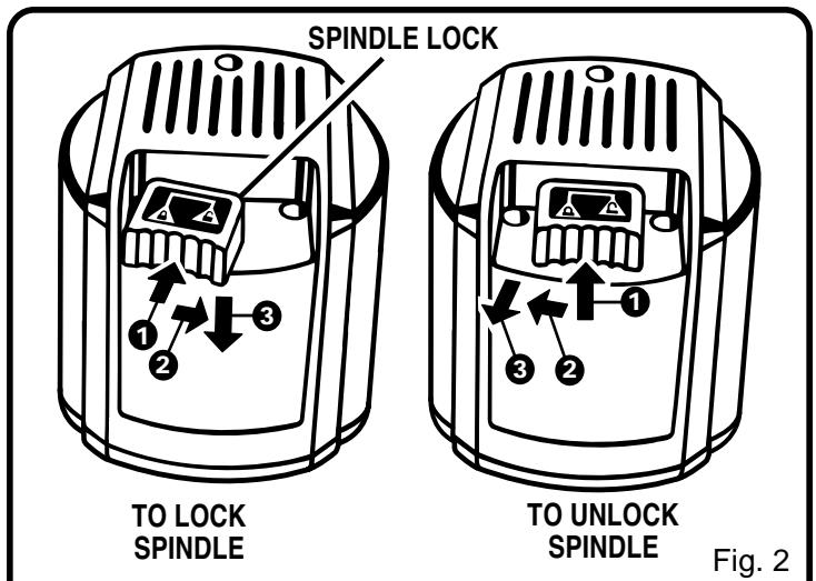
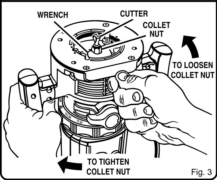
INSTALLING/REMOVING CUTTERS
See Figures 2 and 3.
Unplug your router.

WARNING:
Failure to unplug your router could result in accidental starting causing serious injury.

CAUTION:
To prevent damage to the spindle or spindle lock, always allow motor to come to a complete stop before engaging spindle lock.
A spindle lock is located on the top of the end cap. See Figure 2. To activate lock: (1) push the spindle lock in, (2) slide into lock position then, (3) release the spindle lock.
- Place your router upside down on a table, then turn the collet nut with a wrench until the lock mechanism interlocks. See Figure 3.
Note: Spindle lock is spring loaded and will snap into position when lock mechanism interlocks.

WARNING:
If you are changing a cutter immediately after use, be careful not to touch the cutter or collet with your hands or fingers. They will get burned because of the heat buildup from cutting. Always use the wrench provided.
- Remove cutters by turning collet nut counterclockwise enough to allow cutter to slip easily from collet. See Figure 3. The collet is machined to precision tolerances to fit cutters with 1/4 in. (6 mm) diameter shank size.
■ With your router still upside down on a table, insert shank of cutter into the collet. The shank of your cutter should be close to but not touching the bottom of collet. - Tighten the collet nut securely by turning clockwise with the wrench provided. See Figure 3. Put spindle lock back in unlock position. Otherwise, the interlocking mechanism of the spindle lock will not let you turn your router on. To unlock spindle: (1) push spindle lock in, (2) slide into unlock position then, (3) release spindle lock. See Figure 2.

WARNING:
Do not use cutters with undersized shanks. Undersized shanks will not tighten properly and could be thrown from the tool causing injury.

WARNING:
Before connecting your router to a power supply, always check to be sure the switch is not in "lock-on" position. Failure to do so could result in accidental starting of your router resulting in possible serious injury.
DEPTH OF CUT ADJUSTMENTS
See Figures 4, 5, 6, and 7.
We recommend that cuts be made at a depth not exceeding 1/8 in. (3 mm) and that several passes be made to reach depths of cut greater than 1/8 in. (3 mm).
Unplug your router.

WARNING:
Failure to unplug your router could result in accidental starting causing serious injury.
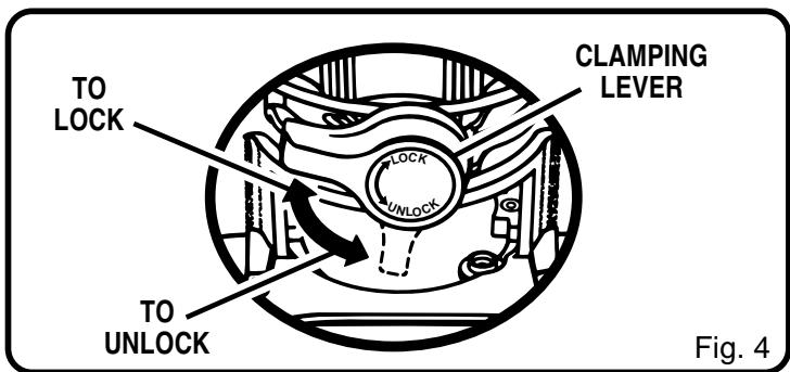
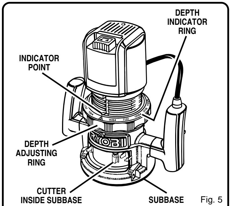
- Place your router on a flat surface, unlock clamping lever, and turn depth adjusting ring until cutter is inside subbase. See Figures 4 and 5.
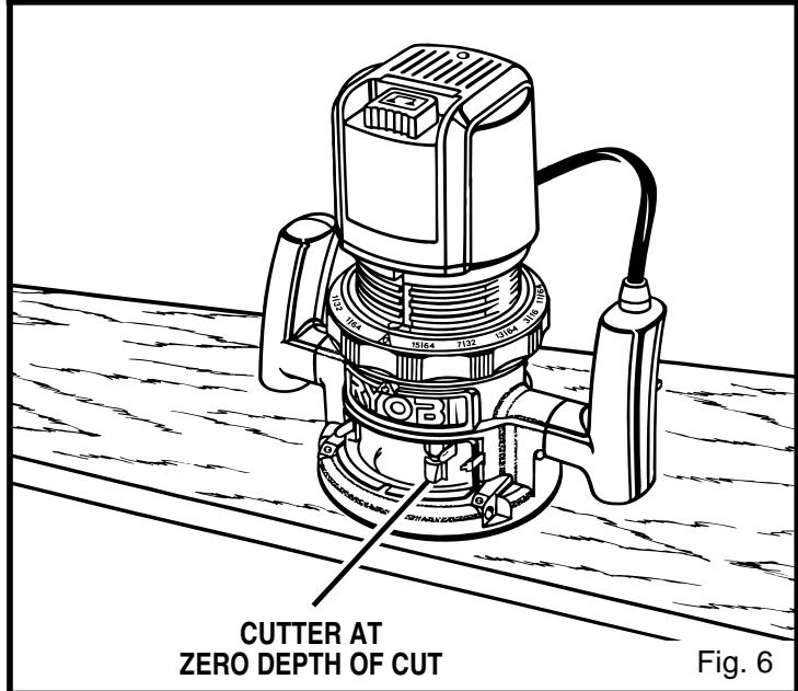
- Turn the depth adjusting ring until tip of cutter touches flat surface (zero depth of cut). See Figure 6. Next turn depth indicator ring until the zero lines up with the indicator point on front of motor housing. See Figure 5.
Position your router so that the cutter can extend below the subbase for desired depth setting. - Turn the depth adjusting ring to obtain the desired depth of cut. The distance the cutter moves can be read on the depth adjusting ring. Each mark on the depth adjusting ring indicates 1/64 in. (0.4 mm) change in depth setting. One indicator point is located on front of the motor housing, the other one is located on the base.
- Lock clamping lever, securing depth adjusting ring to motor housing and base.
DEPTH OF CUT ADJUSTMENTS WHEN ROUTER IS MOUNTED TO A ROUTER TABLE
See Figure 7.
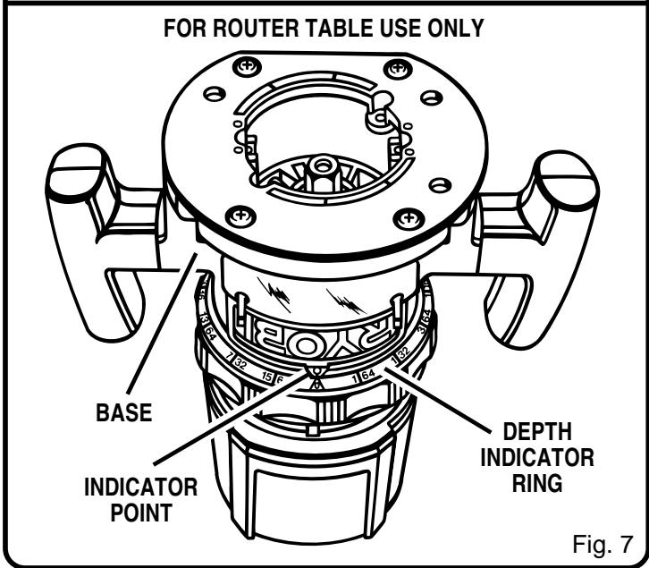
The depth of cut is readable from both sides of the depth adjusting ring. There is a depth indicator ring and indicator point on both sides of the depth adjusting ring. The bottom ring is convenient when using your router mounted to a router table. The indicator point on the base should also be used when using your router mounted to a router table.
The depth indicator rings are identical parts. Therefore, when you have your router mounted upside down on a router table, you set depth of cut by reading the scale different. Set the cutter at zero depth of cut, rotate depth indicator ring to desired depth of cut on the scale, then turn depth adjusting ring back to zero depth of cut and lock clamping lever securely.

WARNING:
Keep a firm grip on router with both hands at all times. Failure to do so could result in loss of control leading to possible serious injury.
For ease of operation and maintaining proper control, your router has two handles, one on each side of the router base. When using your router hold it firmly with both hands as shown in Figure 8. Turn router on and let motor build to its full speed, then gradually feed cutter into workpiece. Remain alert and watch what you are doing. Do not operate router when fatigued.
PROPER FEEDING
The right feed is neither too fast nor too slow. It is the rate at which the bit is being advanced firmly and surely to produce a continuous spiral of uniform chips — without hogging into the wood to make large individual chips or, on the other hand, to create only sawdust. If you are making a small diameter, shallow groove in soft, dry wood, the proper feed may be about as fast as you can travel your router along your guide line. On the other hand, if the bit is a large one, the cut is deep or the wood is hard to cut, the proper feed may be a very slow one. Then, again, a cross-grain cut may require a slower pace than an identical with grain cut in the same workpiece.
There is no fixed rule. You will learn by experience. . . by listening to the router motor and by feeling the progress of each cut. If at all possible, always test a cut on a scrap piece of the workpiece wood, beforehand.
RATE OF FEED
IMPORTANT: The whole "secret" of professional routing and edge shaping lies in making a careful setup for the cut to be made and in selecting the proper rate of feed.
FORCE FEEDING
Clean, smooth routing and edge shaping can be done only when the bit is revolving at a relatively high speed and is taking very small bites to produce tiny, cleanly severed chips. If your router is forced to move forward too fast, the RPM of the bit becomes slower than normal in relation to its forward movement. As a result, the bit must take bigger bites as it revolves. "Bigger bites" mean bigger chips, and a rougher finish. Bigger chips also require more power, which could result in the router motor becoming overloaded.
Under extreme force-feeding conditions the relative RPM of the bit can become so slow—and the bites it has to take so large—that chips will be partially knocked off (rather than fully cut off), with resulting splintering and gouging of the workpiece. See Figure 9.
Your router is an extremely high-speed tool (25,000 RPM no-load speed), and will make clean, smooth cuts if allowed to run freely without the overload of a forced (too fast) feed. Three things that cause "force feeding" are bit size, depth-of-cut, and workpiece characteristics. The larger the bit or the deeper the cut, the more slowly the router should
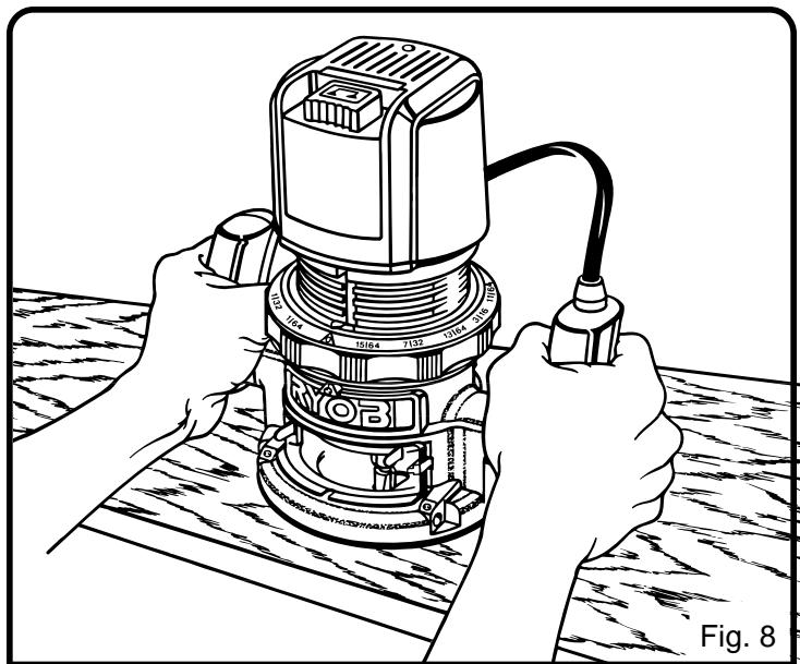
Fig. 8
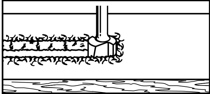
TOO FAST
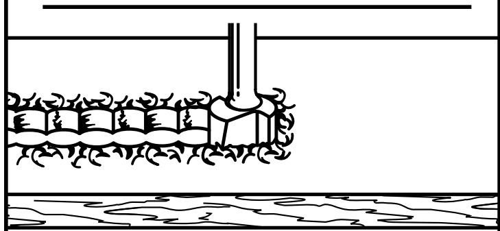
TOO SLOW
Fig. 9
be advanced. If the wood is very hard, knotty, gummy or damp, the operation must be slowed still more.
You can always detect "force feeding" by the sound of the motor. Its high-pitched whine will sound lower and stronger as it loses speed. Also, the strain of holding the tool will be noticeably increased.
TOO SLOW FEEDING
It is also possible to spoil a cut by moving the router forward too slowly. When it is advanced into the work too slowly, a revolving bit does not dig into new wood fast enough to take a bite; instead, it simply scrapes away sawdust-like particles. Scraping produces heat, which can glaze, burn, or mar the cut—in extreme cases, can even overheat the bit so as to destroy its hardness.

WARNING:
Keep a firm grip on router with both hands at all times. Failure to do so could result in loss of control leading to possible serious injury.
TOO SLOW FEEDING (Continued)
In addition, it is more difficult to control a router when the bit is scraping instead of cutting. With practically no load on the motor the bit will be revolving at close to top RPM, and will have a much greater than normal tendency to bounce off the sides of the cut (especially, if the wood has a pronounced grain with hard and soft areas). As a result, the cut produced may have rippled, instead of straight sides. See Figure 9.
"Too-slow feeding" can also cause your router to take off in a wrong direction from the intended line of cut. Always grasp and hold your router firmly with both hands when routing.
You can detect "too-slow feeding" by the runaway too-highly pitched sound of the motor; or by feeling the "wiggle" of the bit in the cut.
DEPTH OF CUT
As previously mentioned, the depth of cut is important because it affects the rate of feed which, in turn, affects the quality of a cut (and, also, the possibility of damage to your router motor and bit). A deep cut requires a slower feed than a shallow one, and a too deep cut will cause you to slow the feed so much that the bit is no longer cutting, it is scraping, instead.
Making a deep cut is never advisable. The smaller bits—especially those only 1/16 in. (1.6 mm) in diameter—are easily broken off when subjected to too much side thrust. A large enough bit may not be broken off, but if the cut is too deep a rough cut will result—and it may be very difficult to guide and control the bit as desired. For these reasons, we recommend that you do not exceed 1/8 in. (3 mm) depth of cut in a single pass, regardless of the bit size or the softness or condition of the workpiece. See Figure 10.
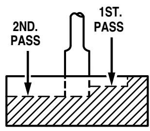
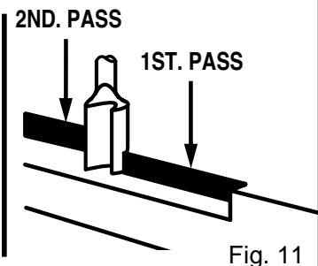
To make deeper cuts it is therefore necessary to make as many successive passes as required, lowering the bit 1/8 in. (3 mm) for each new pass. In order to save time, do all the cutting necessary at one depth setting, before lowering the bit for the next pass. This will also assure a uniform depth when the final pass is completed. See Figure 11.
DIRECTION OF FEED AND THRUST
The router motor and bit revolve in a clockwise direction. This gives the tool a slight tendency to twist (in your hands) in a counterclockwise direction, especially when the motor revs up (as at starting).
Because of the extremely high speed of bit rotation during a "proper feeding" operation, there is very little kickback to contend with under normal conditions. However, should the
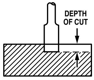
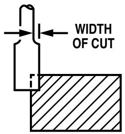
Fig. 10

GUIDE OUTSIDE
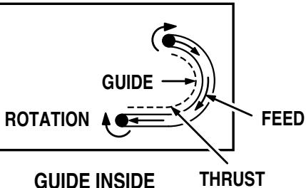
Fig. 12
bit strike a knot, hard grain, foreign object, etc. that would affect the normal progress of the cutting action, there will be a slight kickback—sufficient to spoil the trueness of your cut if you are not prepared. Such a kickback is always in the direction opposite to the direction of bit rotation.
To guard against such a kickback, plan your setup and direction of feed so that you will always be thrusting the tool—to hold it against whatever you are using to guide the cut—in the same direction that the leading edge of the bit is moving. In short, the thrust should be in a direction that keeps the sharp edges of the bit continuously biting straight into new (uncut) wood.

WARNING:
Keep a firm grip on router with both hands at all times. Failure to do so could result in loss of control leading to possible serious injury.
ROUTING
Whenever you are routing a groove, your travel should be in a direction that places whatever guide you are using at the right-hand side. In short, when the guide is positioned as shown in the first part of Figure 12, tool travel should be left to right and counterclockwise around curves. When the guide is positioned as shown in the second part of Figure 12, tool travel should be right to left and clockwise around curves. If there is a choice, the first setup is generally the easiest to use. In either case, the sideways thrust you use is against the guide.
STARTING AND ENDING A CUT INTERNAL ROUTING
Tilt router and place on workpiece, letting edge of subbase contact workpiece first. Be careful not to let router bit contact workpiece. Turn router on and let motor build to its full speed. Gradually feed cutter into workpiece until subbase is level with workpiece.
Upon completion of cut, turn motor off and let it come to a complete stop before removing router from work surface.

WARNING:
Never pull router out of work and place upside down on work surface before the cutter stops. Failure to do so could result in possible serious injury.
EDGING WITH PILOT BITS
The arbor-type bits with pilots are excellent for quick, easy, edge shaping of any workpiece edge that is either straight or curved at a curvature as great or greater than the radius of the bit to be used. The pilot prevents the bit from making too deep a cut; and holding the pilot firmly in contact with the workpiece edge throughout prevents the cut from becoming too shallow.
Whenever the workpiece thickness together with the desired depth of cut (as adjusted by router depth setting) are such that only the top part of the edge is to be shaped (leaving at least a 1/16 in. (1.6 mm) thick uncut portion at bottom), the pilot can ride against the uncut portion, which will serve to guide it. See Figure 13. However, if the workpiece is too thin or the bit set too low so that there will be no uncut edge to ride the pilot against, an extra board to act as a guide must be placed under the workpiece. This "guide" board must have exactly the same contour—straight or curved—as the workpiece edge. If it is positioned so that its edge is flush with the workpiece edge, the bit will make a full cut (in as far as the bit radius). On the other hand, if the guide is positioned as shown in Figure 13 (out from the workpiece edge), the bit
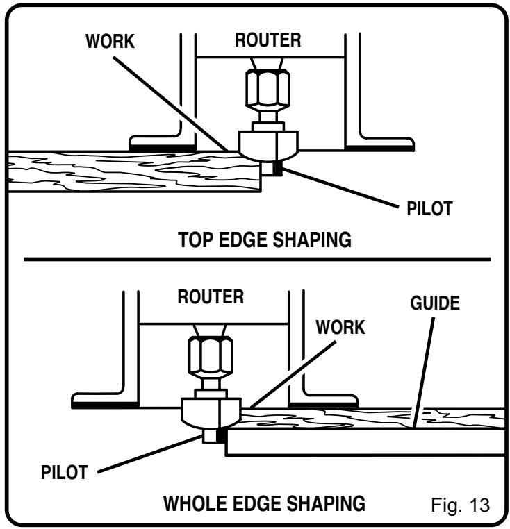
will make less than a full cut — which will alter the shape of the finished edge.
Note: Any of the piloted bits can be used without a pilot for edge shaping with guides, as preceding. The size (diameter) of the pilot that is used determines the maximum cut width that can be made with the pilot against the workpiece edge. The small pilot exposes all of the bit; the large one reduces this amount by 1/16 in. (1.6 mm).
EDGE ROUTING
Place router on workpiece, making sure the router bit does not contact workpiece. Turn router on and let motor build to its full speed. Begin your cut, gradually feeding cutter into workpiece.

WARNING:
Keep a firm grip on router with both hands at all times. Failure to do so could result in loss of control leading to possible serious injury.
Upon completion of cut, turn motor off and let it come to a complete stop before removing router from work surface.

WARNING:
Never pull router out of work and place upside down on work surface before the cutter stops. Failure to do so could result in possible serious injury.

WARNING:
Keep a firm grip on router with both hands at all times. Failure to do so could result in loss of control leading to possible serious injury.
FREEHAND ROUTING
See Figure 14.
When used freehand, your router becomes a flexible and versatile tool. This flexibility makes it possible to easily rout signs, relief sculptures, etc.
There are two basic techniques for freehand routing:
■ Routing letters, grooves, and patterns into wood. See Figure 14.
- Routing out the background, leaving the letters or pattern raised above the surface.
When freehand routing, we suggest the following:
Draw or layout the pattern on workpiece.
Choose the appropriate cutter.
Note: A core box or V-groove bit is often used for routing letters and engraving objects. Straight bits and ball mills are often used to make relief carvings. Veining bits are used to carve small, intricate details.
- Rout the pattern in two or more passes. Make the first pass at 25 percent of the desired depth of cut. This will provide better control as well as being a guide for the next pass.
■ Do not rout deeper than 1/8 in. (3 mm) per pass or cut.

WARNING:
Do not use large router bits for freehand routing. Use of large router bits when freehand routing could cause loss of control or create other hazardous conditions that could cause possible serious personal injury.
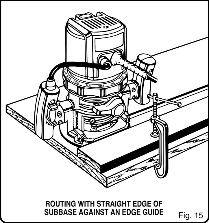
ROUTING WITH STRAIGHT EDGE OF SUBBASE
See Figure 15.
The subbase on your router has a straight edge. It should be used when placing your router against an edge guide or fence and routing grooves parallel to the fence.

WARNING:
ALWAYS make sure the shank of the router bit is seated within 1/16 in. of the bottom of the collet. Extending the shank of the router bit more than 1/16 in. beyond the base of the collet could cause improper engagement of the collet to the bit and result in serious personal injury.
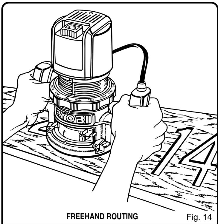
Fig. 14
OPERATION
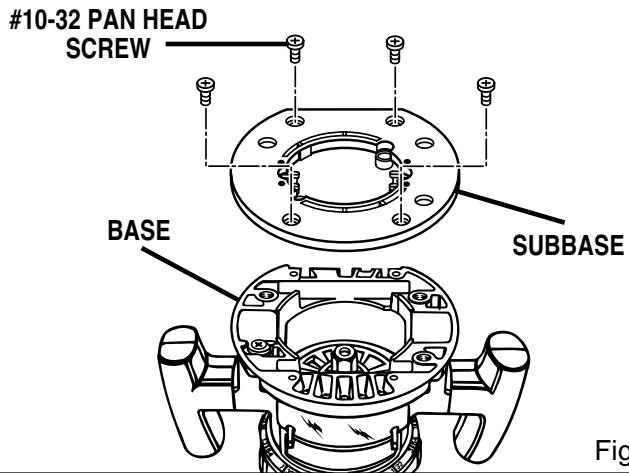
Fig. 16
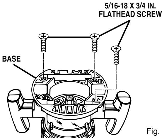
Fig. 17

WARNING:
Do not use with router tables that fail to conform to safe wood working practices and offer proper guarding for the cutter. Failure to comply can result in an accident causing possible serious injury.
ROUTER TABLE USE
See Figures 16 and 17.
- Your router can be used on UL listed router tables such as the Ryobi BT3000SXI Precision Cutting System. It may be necessary to remove the subbase to utilize the full pattern of some edge forming bits such as Roman Ogee and round-over bits. Remove the four (4) #10-32 pan head screws and subbase. With the subbase base removed, the router is secured to the mounting plate with 5 / 16 - 18 × 3 / 4 in., tapered flat head screws provided in the Ryobi Router Mounting Kit model number 4950300 or available at your local hardware store.

WARNING:
Use only 5/16-18 x 3/4 in. machine screws to mount the router in an inverted position for table use. The use of smaller screws, such as the #10-32 machine screws provided for mounting the subbase, could provide an insecure mounting and result in the risk of serious personal injury.

WARNING:
When using a UL listed router table, large router bits should be used for edging only. Do not use router bits that are larger in diameter than the opening in router base for any purpose. Failure to heed this warning could result in serious personal injury.
MAINTENANCE

WARNING:
When servicing use only identical Ryobi replacement parts. Use of any other parts may create a hazard or cause product damage.

WARNING:
Failure to unplug your router could result in accidental starting causing serious injury.
GENERAL
Avoid using solvents when cleaning plastic parts. Most plastics are susceptible to damage from various types of commercial solvents and may be damaged by their use. Use clean cloths to remove dirt, carbon dust, etc.

WARNING:
Do not at any time let brake fluids, gasoline, petroleum-based products, penetrating oils, etc. come in contact with plastic parts. They contain chemicals that can damage, weaken, or destroy plastic.
When electric tools are used on fiberglass boats, sports cars, wallboard, spackling compounds, or plaster, it has been found that they are subject to accelerated wear and possible premature failure, as the fiberglass chips and grindings are highly abrasive to bearings, brushes, commutators, etc. Consequently, it is not recommended that this tool be used for extended work on any fiberglass material, wallboard, spackling compounds, or plaster. During any use on these materials, it is extremely important that the tool is cleaned frequently by blowing with an air jet.
PROPER CARE OF CUTTERS
Get faster more accurate cutting results by keeping cutters clean and sharp. Remove all accumulated pitch and gum from cutters after each use.
When sharpening cutters, sharpen only the inside of the cutting edge. Never grind the outside diameter. Be sure when sharpening the end of a cutter to grind the clearance angle the same as originally ground.
PROPER CARE OF COLLET
From time to time, it also becomes necessary to clean your collet and collet nut. To do so, simply remove collet nut from collet and clean the dust and chips that have collected. Then return collet nut to its original position. Do not tighten collet nut on collet without a cutter installed.

WARNING:
Always wear safety goggles or safety glasses with side shields when operating your router. Failure to do so could result in dust, shavings, loose particles or foreign objects being thrown into your eyes, causing possible serious injury.
LUBRICATION
All of the bearings in this tool are lubricated with a sufficient amount of high grade lubricant for the life of the unit under normal operating conditions. Therefore, no further lubrication is required.
HELPFUL HINTS
Always clamp workpiece securely before routing.
A safe operator is one who thinks ahead.
Always wear eye protection when routing.
Make setup adjustments carefully. Then double check. Measure twice and cut once.
Keep cutters clean and properly sharpened.
√ Don't let familiarity make you careless.
Study all safety rules and do the job safely.
NEVER place your hands in jeopardy.
Make certain clamps can't loosen while in use.
Test difficult setups on scrap — Don't waste lumber.
Plan each operation before you begin.
Clean your router frequently. This will provide smoother operation of depth adjusting ring and clamping lever areas. Shake router or blow with an air jet to remove sawdust buildup.
THINK SAFETY BY THINKING AHEAD.
OPTIONAL ACCESSORIES
The following recommended accessories are current and were available at the time this manual was printed:
| ITEM NO. | DESCRIPTION |
| 4070175 | Template Guide Adapter For Ryobi Template Guides |
| 4070176 | Template Guide Adapter For Porter Cable Rockwell and B&D Template Guides |
| 6090080 | Straight Guide For Ryobi Routers - Model Nos. R160, R161, R165, R175, R180, RE170, RE170VS, RE175, and RE185 |
EXTENSION CORD CAUTION
When using a power tool at a considerable distance from a power source, be sure to use an extension cord that has the capacity to handle the current the tool will draw. An undersized cord will cause a drop in line voltage, resulting in overheating and loss of power. Use the chart to determine the minimum wire size required in an extension cord. Only round jacketed cords should be used.
When working with a tool outdoors, use an extension cord that is designed for outside use. This is indicated by the letters "WA" on the cord's jacket.
Before using any extension cord, inspect it for loose or exposed wires and cut or worn insulation.
**Ampere rating
(on tool data plate) 0-2.0 2.1-3.4 3.5-5.0 5.1-7.0 7.1-12.0 12.1-16.0
Cord Length
Wire Size (A.W.G.)
25' 16 16 16 14 14
50' 16 16 16 14 14 12
CAUTION: Keep the extension cord clear of the working area. Position the cord so that it will not get caught on workpiece, tools, or other obstructions while you are working with a power tool.
**Used on 12 gauge - 20 amp circuit.
- SERVICE
Now that you have purchased your tool, should a need ever exist for repair parts or service, simply contact your nearest Ryobi Authorized Service Center. Be sure to provide all pertinent facts when you call or visit. Please call 1-800-525-2579 for your nearest Ryobi Authorized Service Center. You can also check our web site at www.ryobitools.com for a complete list of Authorized Service Centers.
- MODEL NO.
The model number and serial number of your tool will be found on a plate attached to the motor housing. Please record the model number and serial number in the space provided below.
- MODEL NUMBER R161
- SERIAL NUMBER