EMS180RV - Sander RYOBI - Free user manual and instructions
Find the device manual for free EMS180RV RYOBI in PDF.
| Brand | RYOBI |
| Model | EMS180RV |
| Product type | Orbital sander |
| Supply voltage | 230-240 V ~ 50 Hz |
| Rated power | 180 W |
| No-load speed (orbital) | 6 000 - 12 000 min⁻¹ |
| Triangular pad dimensions | 168 x 100 mm |
| 1/3 sheet pad dimensions | 185 x 92 mm |
| Weight | 1.4 kg |
| Speed variator | Electronic |
| Abrasive fixing | Self-adhesive (Velcro) |
| Dust collector | Integrated with housing |
| Sanding finger | Integrated |
| Double insulation | Yes |
| Sound pressure level (Lp) | 81.9 dB(A) (K=3 dB(A)) |
| Sound power level (Lw) | 92.9 dB(A) (K=3 dB(A)) |
| Vibration level (ah) | 5.65 m/s² (K=1.5 m/s²) |
| Warranty | 24 months |
| Main applications | Sanding wood, removing rust, polishing metals and porcelain |
| Pad maintenance | Clean with warm water and dry flat |
Frequently Asked Questions - EMS180RV RYOBI
User questions about EMS180RV RYOBI
0 question about this device. Answer the ones you know or ask your own.
Ask a new question about this device
Download the instructions for your Sander in PDF format for free! Find your manual EMS180RV - RYOBI and take your electronic device back in hand. On this page are published all the documents necessary for the use of your device. EMS180RV by RYOBI.
USER MANUAL EMS180RV RYOBI
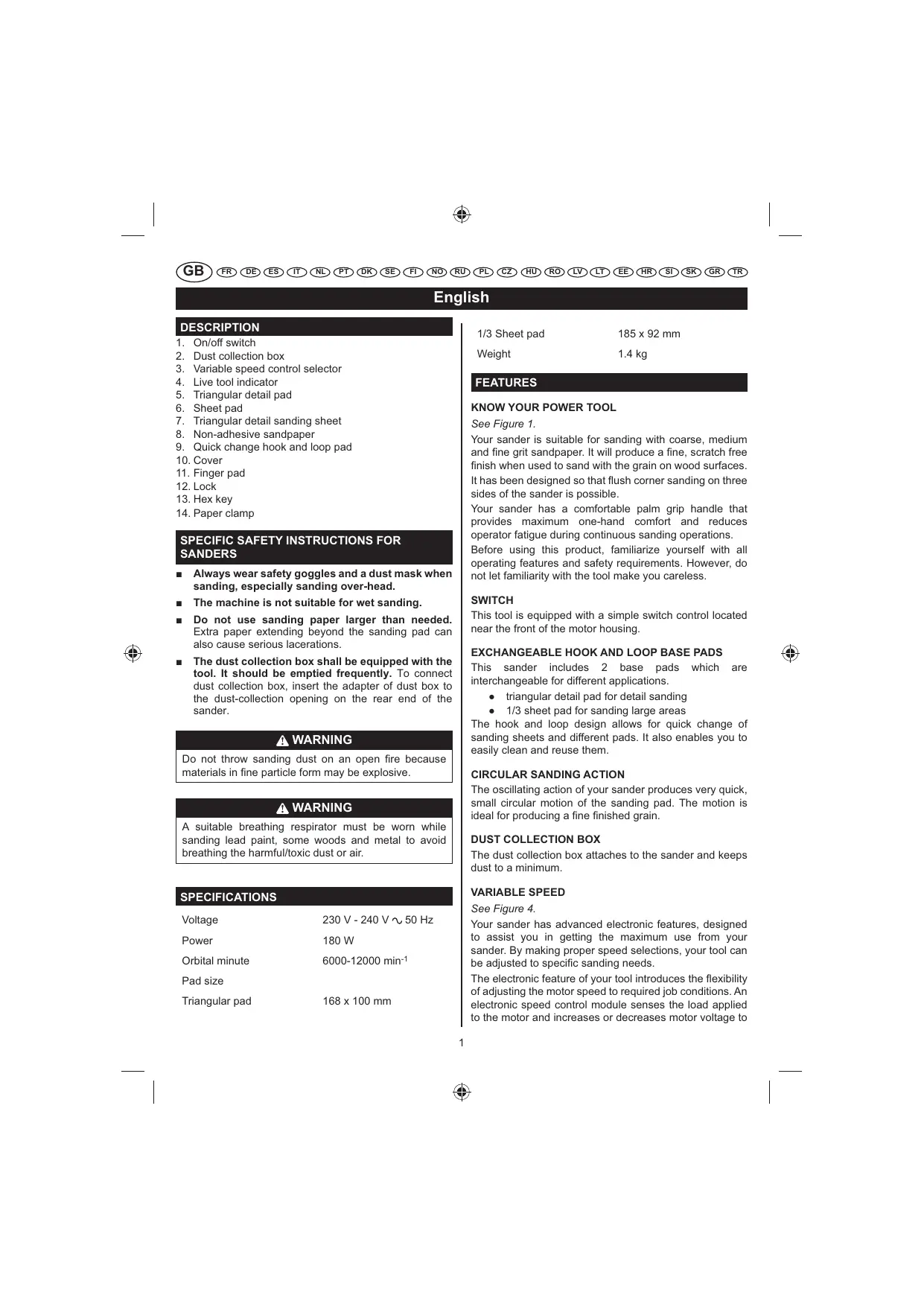
- On/off switch
- Dust collection box
- Variable speed control selector
- Live tool indicator
- Triangular detail pad
- Sheet pad
- Triangular detail sanding sheet
- Non-adhesive sandpaper
- Quick change hook and loop pad
- Cover
- Finger pad
- Lock
- Hex key
- Paper clamp
SPECIFIC SAFETY INSTRUCTIONS FOR SANDERS
Always wear safety goggles and a dust mask when sanding, especially sanding over-head.
The machine is not suitable for wet sanding.
- Do not use sanding paper larger than needed. Extra paper extending beyond the sanding pad can also cause serious lacerations.
- The dust collection box shall be equipped with the tool. It should be emptied frequently. To connect dust collection box, insert the adapter of dust box to the dust-collection opening on the rear end of the sander.
WARNING
Do not throw sanding dust on an open fire because materials in fine particle form may be explosive.
WARNING
A suitable breathing respirator must be worn while sanding lead paint, some woods and metal to avoid breathing the harmful/toxic dust or air.
SPECIFICATIONS
Voltage 230V-240V\~50Hz
Power 180W
Orbital minute 6000-12000 min-1
Pad size
Triangular pad 168 x 100 mm
1/3 Sheet pad 185 × 92 ~mm
Weight 1.4 kg
FEATURES
Your sander is suitable for sanding with coarse, medium and fine grit sandpaper. It will produce a fine, scratch free finish when used to sand with the grain on wood surfaces. It has been designed so that flush corner sanding on three sides of the sander is possible.
Your sander has a comfortable palm grip handle that provides maximum one-hand comfort and reduces operator fatigue during continuous sanding operations.
Before using this product, familiarize yourself with all operating features and safety requirements. However, do not let familiarity with the tool make you careless.
SWITCH
This tool is equipped with a simple switch control located near the front of the motor housing.
EXCHANGEABLE HOOK AND LOOP BASE PADS
This sander includes 2 base pads which are interchangeable for different applications.
triangular detail pad for detail sanding
1/3 sheet pad for sanding large areas
The hook and loop design allows for quick change of sanding sheets and different pads. It also enables you to easily clean and reuse them.
CIRCULAR SANDING ACTION
The oscillating action of your sander produces very quick, small circular motion of the sanding pad. The motion is ideal for producing a fine finished grain.
DUST COLLECTION BOX
The dust collection box attaches to the sander and keeps dust to a minimum.
VARIABLE SPEED
See Figure 4.
Your sander has advanced electronic features, designed to assist you in getting the maximum use from your sander. By making proper speed selections, your tool can be adjusted to specific sanding needs.
The electronic feature of your tool introduces the flexibility of adjusting the motor speed to required job conditions. An electronic speed control module senses the load applied to the motor and increases or decreases motor voltage to
English
compensate for and maintain desired RPM. Speed can be set according to the sanding purpose or the surface of the workpiece you will be using. Select clockwise to increase speed for rough surfaces or for quick removal of stock and anti-clockwise to decrease speed for the smaller, delicate sanding applications.
ASSEMBLY
WARNING
The tool should never be connected to a power supply when you are assembling parts, making adjustments, cleaning, performing maintenance, or when the tool is not in use. Disconnecting the tool will prevent accidental starting that could cause serious injury.
SANDPAPER SELECTION
Selecting the correct size, grit and type of sand paper is an extremely important step in achieving a high quality sanded finish. Aluminum oxide, silicon carbide, and other synthetic abrasives are best for power sanding. Natural abrasives, such as flint and garnet are too soft for economical use in power sanding.
In general, coarse grit will remove the most material and finer grit will produce the best finish in all sanding operations. The condition of the surface to be sanded will determine which grit will do the job. If the surface is rough, start with a coarse grit and sand until the surface is uniform. Medium grit may then be used to remove scratches left by the coarser grit and finer grit used for finishing of the surface. Always continue sanding with each grit until surface is uniform.
WARNING
Do not use sander without sandpaper, doing so will damage the cushion.
Sheet/pad recommended use
80-grit sanding sheet
Coarse sanding
120-grit sanding sheet
Light sanding
150-grit sanding sheet
Light sanding
ATTACHING HOOK AND LOOP SANDING DISCS
See Figure 2.
- Unplug the sander.
- Align holes in hook and loop type sanding disc with holes in pad, then carefully press fuzzy side of sanding disc against pad as tightly as possible.
NOTE: It is recommended that you keep the sanding disc
backing pad clean to provide for best adhesion. Clean occasionally by brushing lightly with a small brush.
ATTACHING THE DUST COLLECTION BOX
See Figure 3.
The dust collection box provides a dust collection system for the sander. Sanding dust is drawn up through the holes of the sanding disc and collected in the dust collection box during sanding.
- Unplug the sander.
- Using a slight twisting motion, firmly slide the dust collection box assembly in the blower exhaust on the sander.
WARNING
Exercise caution when using this tool. Careless actions, for even a fraction of a second, can result in serious personal injury.
APPLICATIONS
You may use the sander for the purposes listed below:
- sanding on wood surfaces
- removing rust from and sanding steel surfaces
polishing and scrubbing porcelain and metal
CAUTION
Keep the cord away from the sanding pad and position the cord so that it will not be caught on lumber, tools, or other objects during sanding.
WARNING
Always wear safety goggles or safety glasses with side shields when operating this tool. Failure to do so could result in dust, shavings, or loose particles being thrown into your eyes, resulting in possible serious injury.
OPERATION
TURNING THE SANDER ON/OFF
See Figure 4.
Turn on the sander: Push the on/off switch to the left.
Turn off the sander: Push the on/off switch to the right.
- Secure the workpiece to prevent it from moving under the sander.
English
WARNING
Unsecured workpieces could be thrown towards the operator, causing injury.
WARNING
Keep your head away from the sander and the sanding area. Your hair could be drawn into the sander causing serious injury.
- Place the sander on the workpiece so that all of the sanding disc surface is in contact with the workpiece.
CAUTION
Avoid damaging the motor from overheating; be careful not to let your hand cover the air vents.
- Turn on the sander and move it slowly over the workpiece.
NOTE: Hold the sander in front and away from you, keeping it clear of the workpiece. Start sander and let the motor build to its maximum speed, then gradually lower the sander onto the workpiece. Move the sander slowly across the workpiece using small circular motions.
Do not force. The weight of the unit supplies adequate pressure, so let the sanding disc and sander do the work. Applying additional pressure only slows the motor, rapidly wears sanding disc and greatly reduces sander speed. Excessive pressure will overload the motor causing possible damage from motor overheating and can result in inferior work. Any finish or resin on wood may soften from the frictional heat.
Do not allow sanding on one spot too long as the sander's rapid action may remove too much material, making the surface uneven.
Extended periods of sanding may tend to overheat the motor. If this occurs, turn sander off and wait until sanding disc comes to a complete stop, then remove it from workpiece. Remove your hand from vent area, remove sanding disc, then with your hand removed from vent area, turn sander on and run it free without a load to cool motor.
CORNERS AND CREVICES
See Figure 6.
For detail sanding such as corners and crevices, use the tip of the sanding pad with small back and forth motions.
For more efficient operation, empty the dust collection box when it is no more than half full. Always empty and clean the dust collection box thoroughly upon completion of a sanding operation and before placing the sander in storage.
WARNING
Collected sanding dust from sanding surface coatings such as polyurethanes, linseed oil, etc., can self-ignite in your sander dust collection box or elsewhere and cause fire. To reduce the risk of fire always empty your dust collection box frequently (10-15 minutes) while sanding and never store or leave a sander without totally emptying its dust collection box. Also follow the recommendations of the coatings manufacturers.
- Unplug the sander.
WARNING
Failure to unplug the tool could result in accidental starting causing possible serious injury.
- Remove the dust collection box from the sander.
- Shake out the dust.
- Reattach the dust collection box to the sander.
NOTE: For a more thorough cleaning of the dust collection box, remove dust collection box from frame and shake out dust. Replace dust collection box over frame then install dust collection box assembly on sander.
CHANGING THE BASE PADS
Sheet and triangular pad
See Figure 8.
- For safety reasons, ensure your tool is unplugged.
- Remove the sanding sheet from the base. Undo the allen screws on the base, using the hex key provided.
- Once all 3 screws have been removed, remove the base.
- When fitting the new base, place the base up to the sander and insert the first screw (do not tighten).
- Insert the remaining 2 screws, then tighten all 3 screws. Tighten up the allen screws opposite to each other.
Place the desired sanding paper on to the base and continue to work.
CAUTION
Remove the sanding sheet when not in use to prevent warping.
English
INSTALLING SANDPAPER
Inspect sandpaper before installing. Do not use if broken or defective.
Hook and loop sandpaper
See Figure 9 - 10.
- Unplug the sander.
- Align holes in hook and loop type sanding disc with holes in pad, then carefully press fuzzy side of sanding disc against pad as tightly as possible.
NOTE: It is recommended that you keep the sanding disc backing pad clean to provide for best adhesion. Clean occasionally by brushing lightly with a small brush.
WARNING
Failure to unplug the tool could result in accidental starting causing possible serious injury.
Non-adhesive sandpaper
See Figure 11.
- Unplug the sander.
- Release the paper clamp. Remove used sandpaper, if any.
- Insert the new sandpaper under the paper clamp.
- Clamp the sandpaper in place.
ORBITAL MOTION
Orbital motion is ideal for fast cutting action when removing old finishes, smoothing rough wood, cutting stock down to required dimensions or for finishing surfaces to be painted. The sandpaper moves in tiny circles at a very high speed, allowing the sander to move easily.
USING THE FINGER PAD
See Figure 11.
- Open the finger pad cover.
- Lower the finger pad and lock it in place.
- Close the finger pad cover.
LIVE TOOL INDICATOR
This tool features a live tool indicator which illuminates as soon as the tool is connected to the supply. This warns the user that the tool is connected and will operate when the switch is pressed.
MAINTENANCE
WARNING
The tool should never be connected to a power supply when you are assembling parts, making adjustments, cleaning, performing maintenance, or when the tool is not in use. Disconnecting the tool will prevent accidental starting that could cause serious injury.
WARNING
When servicing, use only identical replacement parts. Use of any other parts may create a hazard or cause product damage.
GENERAL
Avoid using solvents when cleaning plastic parts. Most plastics are susceptible to various types of commercial solvents and may be damaged by their use. Use clean cloths to remove dirt, carbon dust, etc.
WARNING
Do not at any time let brake fluids, gasoline, petroleum-based products, penetrating oils, etc., come in contact with plastic parts. They contain chemicals that can damage, weaken or destroy plastic.
Electric tools used on fiberglass material, wallboard, spackling compounds, or plaster are subject to accelerated wear and possible premature failure because the fiberglass chips and grindings are highly abrasive to bearings, brushes, commutators, etc.. Consequently, we do not recommended that this tool be used for extended work on these types of materials. However, if you do work with any of these materials, it is extremely important to clean the tool using compressed air.
WARNING
Always wear safety goggles or safety glasses with side shields during power tool operation or when blowing dust. If operation is dusty, also wear a dust mask.
LUBRICATION
All of the bearings in this tool are lubricated with a sufficient amount of high grade lubricant for the life of the unit under normal operating conditions. Therefore, no further lubrication is required.
English
CLEANING THE SCRUBBING PADS
To ensure longer life and optimum performance, periodically clean all sanding residue and foreign materials from the scrubbing pads. This can be done simply by rinsing the pad with warm water until all foreign material has been washed away. After cleaning, gently squeeze the pad to remove excess water and allow pad to dry. Always store pads and sanding sheets flat in a cool dry location.
CLEANING THE SANDING SHEETS
The sanding sheets that came with your sander are made to be re-used. Therefore, it is important that they be cleaned periodically to remove sanding residue and foreign material that can accumulate over time.
To clean sanding sheets, rub the sheets with a hard rubber block. You can also use the clean rubber sole of a shoe.
WARNING
Always remove scrubbing or sanding pad from sander before cleaning. Failure to do so could cause serious personal injury.
ENVIRONMENTAL PROTECTION

Recycle raw materials instead of disposing of as waste. The machine, accessories and packaging should be sorted for environmental-friendly recycling.
SYMBOL

Safety Alert
V Volts
Hz Hertz
Alternating Current
W Watts
No No-load speed
min-1 Revolutions or reciprocations per minute

Orbital diameter

CE Conformity

Double insulation

Wear ear protection

Wear eye protection

Please read the instructions carefully before starting the machine.

Waste electrical products should not be disposed of with household waste. Please recycle where facilities exist. Check with your Local Authority or retailer for recycling advice.
Français
DESCRIPTION
Sildenafil has been shown to be effective in the treatment of erectile dysfunction.
TOMNING AF STVBOKSEN
Sefigur7.
TOMMING AV STVBOKSEN
Se fig. 7.
山nfoBaIbHa MaHnHa npeyCMOTpeHa nnr 1nfoBaHnO T Kpa Do Kpa C Tpex CTopoH.
山nФOBaBbA MaINHa OcHauHa yObHou pa6oey pyKoI.
Ipeed nCnOlb3OBaHHeM DaHHoro yCTpOJCTBa O3HAKOMbTeCb CO BCEMM pEKMAMn pa6OTbl N Tpe6OBaHNMym TexNkn 6e3oNaChOCTn. OdHako 3HaHne INHCTpyMeHTe DOnJXHO CnyXNTb NOBODm DnA B6ecNeuHOctn.
BbIKJIIOYATEJIb
DaHHbI INHCTpyMeHT IMeET npocToB BbIKIOUaTeNb, paCNOJoxHeHHb Ha nepeDHeu qactn Kopnyca DBIrataJIe.
CMEHHbI IIOOUBBi
山nfoBaIbHa MaIina NMeet 2 CmEHhie NoIOuBbl dIpa3InuHbIX TINOB pa6oT:
TpeyrolbnaI NOO dNra TOHKO WnIOBKn;
- noooba 1/3 nicta dny 60jbuxn nobepxhoctei;
CamaKNeEOUaCraShIMDPOBaNbA 6yMaRaMeHReTcIeKo N bCTpO TaKaONcHTpyuOnBHeYnXnCTky nNo3BOJrE NOBTOPHOICNONsOBATbIX.
KPYROBOEJINΦOBAHNE
Bn6paHNOHoe DeiCTBHe ⅢINΦOBAIbHOro INCHcpyMeHTa NO3BOJrET pNDAtB ⅢINΦOBAIbHOH NaJIaIKe OChEB 6bICTPOE KpyROBo E BnKHeNe MaIOn aMnPTybl. Tako DnBnKHeNe XopoIo NoDxOJTДЯ NpOuYeHnN NOBepXHOCTN C MeIKoN 3ePHNCTOCTbIO.
KOHTENHEP DIA CBOPA TbIN
COOTBETCTBNE Tpe6oBaHnM CE

ДВОИнэиЗЛЯЦА

PpIMMeHnTe cpeDCTBa 3aunTbI opraHOB cnyxa

PpIMMeHnTe CpeDCTBa 3aUHTbI OprAHOB 3peHn

Ppepe nCnoBbOBAHnEM npi6opa BHMaTeJbHO 03HaKoMbTeCb C daHHo nHCTpyKuien.
Otpa6oTaHHa 3neKtpoTeXnHccka npOkyu ndoJxHa yHuHToxatbCBAmte C bIbTOBIMN OTXDAMNI. YtINnHpyUte, ecIn nMeetc nceuaJIbHOe TexHnueckoe obopyoBaHme. IOp Bonpocam yTnIn3aunn pOKoHCyblTnpYiTecb C MeCTbIM OprAHOM Bnacti nn npedPnraTneM po3HnHOn TropOBnn.
Polski
OPIS
RUCH POSUWISTO-ZWROTNY
SBERNA NADOBA PRACHU
Nádoba pro prach se pripojue k brusce a udrzije prach na minimu.
Cestina
PROMÉNNÁ RYCHLOST
Viz obrazek 4.
Bruska je vybavana elektronickym regulatorem rychlosti, ktery umoznije nastavit optimalin otacky motoru. Provedenim vbyer spravné rychlosti se vaš nastroj sefi di na speficité potfeby.

m = 311 ;

m = 311 ;
All Ryobi products are guaranteed against manufacturing defects and defective parts for a period of twenty-four (24) months from the date stated on the original invoice drawn up by the retailer and given to the end user.
Deterioration caused by normal wear and tear, unauthorised or improper use or maintenance, or overload are excluded from this guarantee as are accessories such as battery packs, light bulbs, blades, fittings, bags, etc. In the event of malfunction during the warranty period, please take the NON-DISMANTLED product, along with the proof of purchase, to your retailer or nearest Authorised Ryobi Service Centre.
This warranty in no way affects your legal rights concerning defective products.

GARANTIE - CONDITIONS
The vibration emission level given in this information sheet has been measured in accordance with a standardised test given in EN 60745 and may be used to compare one tool with another. It may be used for a preliminary assessment of exposure. The declared vibration emission level represents the main applications of the tool. However if the tool is used for different applications, with different accessories or poorly maintained, the vibration emission may differ. This may significantly increase the exposure level over the total working period.
An estimation of the level of exposure to vibration should also take into account the times when the tool is switched off or when it is running but not actually doing the job. This may significantly reduce the exposure level over the total working period. Identify additional safety measures to protect the operator from the effects of vibration such as: maintain the tool and the accessories, keep the hands warm, organisation of work patterns.
FR
AVERTISSEMENT
DECLARATION OF CONFORMITY
We declare under our sole responsibility that this product is in conformity with the following standards or standardized documents: 2006/42/EC, 2004/108/EC, EN55014-1, EN55014-2, EN61000-3-2, EN61000-3-3, EN60745-1, EN60745-2-4, EN62233 Noise level [K = 3dB(A)] .. Lp = 81.9dB(A) Lw = 92.9dB(A) Vibration level [K] = 1.5m / s .. ah = 5.65m / s^2

Déclaration de CONFORMITE
Address: 24/F, CDW BUILDING, 388 CASTLE PEAK ROAD, TSUEN WAN, HONG KONG.
Web: www.ttigroup.com
Name/Title: Brian Ellis / Vice President - Engineering
Signature:

Jul 15, 2010
Technical File at
Name of company: TECHTRONIC INDUSTRIES UK (LTD.)
Address: MEDINA HOUSE, FIELDHOUSE LANE, MARLOW, BUCKS, SL7 1TB, UNITED KINGDOM.
Web: www.ttigroup.com
Name/Title: Carl A. Jeffries / Head of Ryobi Product Marketing
Signature:

Trademarks:
The use of the trademark Ryobi is pursuant to a license granted by Ryobi Limited.