
EY75A8 - Screwdriver PANASONIC - Free user manual and instructions
Find the device manual for free EY75A8 PANASONIC in PDF.

| Brand | Panasonic |
| Model | EY75A8 |
| Product type | Cordless impact driver |
| Power supply | 18 V DC Li-ion battery |
| No-load speed (Soft mode) | 0 – 1,000 rpm |
| No-load speed (Medium mode) | 0 – 1,500 rpm |
| No-load speed (Hard mode) | 0 – 2,300 rpm |
| Impact rate (Soft mode) | 0 – 1,900 bpm |
| Impact rate (Medium mode) | 0 – 2,900 bpm |
| Impact rate (Hard mode) | 0 – 3,400 bpm |
| Max torque | 280 N·m (28.6 kgf·m) |
| Total length | 143 mm |
| Weight (with battery EY9L54) | 1.80 kg |
| Screwing capacities (wood screws) | up to 9.5 mm |
| Screwing capacities (standard bolts) | M10 – M20 |
| Chuck | Hexagonal 6.35 mm (quick-change) |
| Safety | Switch lock, motor/battery overheat protection |
| Maintenance | Clean with a dry cloth, do not use water or solvent |
| Spare parts | Batteries, charger, optional chuck EY9HX131E |
| Warranty | Extended warranty available, excluding prolonged heavy use |
Frequently Asked Questions - EY75A8 PANASONIC
User questions about EY75A8 PANASONIC
0 question about this device. Answer the ones you know or ask your own.
Ask a new question about this device
Download the instructions for your Screwdriver in PDF format for free! Find your manual EY75A8 - PANASONIC and take your electronic device back in hand. On this page are published all the documents necessary for the use of your device. EY75A8 by PANASONIC.
USER MANUAL EY75A8 PANASONIC
Cordless Impact Driver / Cordless Impact Wrench
natural_image
Line drawings of two different types of electric drill heads (no text or symbols)EY75A7 EY75A8
Before operating this unit, please read these instructions completely and save this manual for future use.
natural_image
Technical drawing of a hexagonal bolt and a threaded shaft with dimension lines (no text or symbols)[Fig.2]

natural_image
Diagram showing a mechanical component with two arrows indicating direction (no text or symbols present)[Fig.3]
Alignment marks
natural_image
Technical line drawing of a handheld device with internal components and directional arrows indicating movement (no text or symbols)[Fig.6]
Pack cover
Akkuabdeckung
Couvercle de la
batterie autonome
Coperchio pacco
Accudeksel
Cubierta de batería
Pakningsdæksel
Batteriskydd
Pakkedeksel
Akkukotelon kansi
Pil takımı kapağı
Osłona akumulatora
Kryt bloku
natural_image
Diagram of a device with a lid and internal components, no text or symbols presentLabel (red or yellow)
Label (rood of geel)
Etiqueta (roja o amarilla)
Battery pack release button
Alignment marks
Original instructions: English Translation of the original instructions: Other languages
Read "the Safety Instructions" booklet and the following before using.
I. ADDITIONAL SAFETY RULES
1) If the bit becomes jammed, immediately turn the trigger switch off to prevent an overload, which can damage the battery pack or motor. Use reverse motion to loosen jammed bits.
2) Do NOT operate the Forward/Reverse lever when the trigger switch is on. The battery will discharge rapidly and damage to the unit may occur.
3) During charging, the charger may become slightly warm. This is normal. Do NOT charge the battery for a long period.
4) Do not strain the tool by holding the speed control trigger halfway (speed control mode) so that the motor stops.
5) To prevent injury during use, hold the tool steady at all times and avoid waving it around.
6) Make certain that there are no hidden gas or water pipes, or electrical wires in the area where you will be working. Coming into contact with hidden pipes or wires could result in electric shock, or water or gas leaks.
7) Make sure to hold the object you are working on steady.
8) Check for damaged parts.
- Check thoroughly for damage to the protective cover and other parts before operating.
- Check to make sure the tool and all of its functions are working properly.
- Check the adjustment of all movable parts, and check all fixed parts to make sure they are fitted properly and free of damage. Check all parts of the tool for abnormal function.
9) When attempting to repair the protective cover or other parts, please follow the instructions in the user manual. In cases where there are no instructions in the manual, please take it back to the store to have it repaired.
10) If the tool gets exceptionally hot during use, please take it in for service and repair.
11) To avoid potential injury, keep face and hands away from the drill bit and any shavings.
12) Do not wear gloves when operating the tool, as they may get caught by the drill, leading to injury.
13) Battery terminals, screw shavings, and tool accessories such as drill bits will be very hot immediately after operation. Do not touch them as there is a risk of burning yourself.
14) Check that there are no underground electric cables, water pipes or gas pipes at the site of use. Contact with underground services may result in an electric shock, short circuit or gas leak.
15) Always stay focused and exercise caution during operation.
- When operating cordless tools, always remember the proper way to use them, pay attention to your surroundings, and exercise caution.
- Use common sense.
- Do not operate the tool when tired.
16) If the device or battery pack emits smoke, do not inhale the smoke.
• They may be harmful to your health.
17) Do not block the vents on the device or charger.
- This may result in scalding or ignition due to abnormal build up of heat.
18) Do not expose skin directly to the hot air emitted from the vents on the device or charger.
19) Do not modify, disassemble or repair the device.
- This may result in fire or electric shock. For repair, contact the place of purchase or the Panasonic customer service desk.
20) Do not use the device or battery pack when coated with a foreign substance such as oil.
- Dropping the device or battery pack may result in damage. Ingress of foreign substances such as oil may result in the overheating, ignition or explosion.
21) Pointed tools such as drill bits should be periodically replaced.
22) Before use, check that the device, battery pack, charger, tools and other parts are free from damage and operate correctly.
- Failure to do so may result in injury due to damage.
23) Securely attach tools such as drill bits and accessories in accordance with the user manual.
- Failure to do so may result in injury due to the tool coming loose.
24) When working at height, ensure nobody is below the work area.
- Failure to do so may result in accident due to materials or the device being dropped.
25) Do not use in locations with large amounts of flammable liquids, gas or dust.
26) Ensure earthed elements such as metal pipes or the housings of heaters, microwaves or refrigerators do not come into contact with your body.
27) Do not use without reading the user manual and safety guidelines and understanding the charging tool and its operation.
28) Be prepared and work with due care.
29) While working, use safety equipment such as protective glasses, and where necessary an anti-dust mask, anti-slip safety boots, helmet and ear protectors.
30) Do not use in the presence of corrosive gases.
31) Be aware that this tool is always in an operating condition, since it does not have to be plugged into an electrical outlet.
32) Turn the trigger switch off immediately if a bit becomes jammed to avoid damage to the battery pack or motor due to overloading. Reversing direction will loosen the jammed bit.
33) When exchanging bits or accessories and during storage, be sure to set the forward/reverse lever to the lock position and remove the battery pack. Failure to do so may result in unexpected operation and injury.
34) Do not store the device above 50 degrees.
• This may result in abnormal operation.
35) Do not operate through a metal hole.
- This may result in injury from splintering of the metal drill blade due to high torque.
36) If storing the device on a hook, do not leave any sharp tool installed, as this may result in injury.
37) Do not use multiple battery packs consecutively.
38) Avoid starting the device suddenly.
39) Make sure the power plug is fully inserted.
- Partial insertion can cause an electric shock or a fire due to the generation of heat. Do not use damaged plugs or loose sockets.
40) Periodically remove dust, etc. from power plugs.
- If dust, etc. collects on a plug, a fire may be caused by poor isolation due to moisture, etc. Unplug the plug and wipe it with a dry cloth.
41) If an unusual sound, odour or amount of heat is produced by the charger during charging, remove the power plug from the socket immediately, disconnect the battery pack, and request inspection and repair from the place of purchase.
42) Inspect the charger periodically to check whether dust has gathered in the vents and that the cooling fan rotates during charging. Continued charging without ensuring good cooling may result in the production of smoke, ignition and explosion.
43) Do not use or charge in a location with flammable liquids or gases.
- This may result in the generation of heat, smoke, ignition or explosion.
44) Do not remove the power plug from the socket with wet hands.
• This may result in electric shock.
45) Remove power plug from socket when not in use.
- Failure to do so may result in electric shock or short circuit and fire due to poor insulation.
46) Use an appropriate power socket for the power plug.
47) Do not modify the power plug.
48) Hold the device steady and avoid waving it around during use. Failure to do so may result in injury.
49) Securely affix in place the work piece to be processed.
Failure to do so may cause unintended movement of the work piece resulting in injury.
For safety, use a securing tool such as a clamp or vice.
50) Do not use the LED light as a flash-light.
As it does not provide sufficient brightness, moving about in a dark location while using the LED light for illumination could result in an accident.
51) During use, do not wear gloves such as work gloves that could get caught by the drill. They could get caught by the rotating portion of the drill, which may result in injury.
52) Do not move violently when using a hook. This could result in damage due to the device falling.
53) During use, do not allow the rotating portion of the drill or cutting scraps to come near your body or parts of your body. The bit could come loose or break unexpectedly, or cutting scraps could come into contact with your body, which may result in injury. Pointed tools such as drill bits should be periodically replaced.
| Symbol Meaning | |
| V | Volts |
| —— | Direct current |
| n_0 | No load speed |
| ... min^-1 | Revolutions or reciprocations per minutes |
| Ah | Electrical capacity of battery pack |
  | Read the operating instructions before use. |
 | For indoor use only. |
WARNING
- Do not use other than the Panasonic battery packs that are designed for use with this rechargeable tool.
- Panasonic is not responsible for any damage or accident caused by the use of recycled or counterfeit battery pack.
- Do not dispose of the battery pack in a fire, or expose it to excessive heat.
- Do not allow metal objects to touch the battery pack terminals.
- Do not carry or store the battery pack in the same container as nails or similar metal objects.
- Do not charge the battery pack in a high-temperature location, such as next to a fire or in direct sunlight. Otherwise, the battery may overheat, catch fire, or explode.
• After removing the battery pack from the tool or the charger, always reattach the pack cover. Otherwise, the battery contacts could be shorted, leading to a risk of fire.
- When the Battery Pack Has Deteriorated, Replace It with a New One. Continued use of a damaged battery pack may result in heat generation, ignition or battery rupture.

WARNING
• To prevent leakage, overheating, smoke generation, fire, and rupturing from occurring, follow these instructions when handling our rechargeable power tools (tool main body/battery pack/charger).
- Do not allow material cuttings or dust to fall onto the battery pack.
- When storing, remove any material cuttings and dust from the battery pack, and place the battery pack separately from metal objects (screws, nails, etc.) when storing in the tool case.
- Do not handle the rechargeable power tools in the following way. (There is a hazard of smoke generation, fire, and rupturing)
- Use or leave in places exposed to rain or moisture
- Use submerging in water
II. ASSEMBLY
NOTE:
When attaching or removing a bit, disconnect battery pack from tool or place the switch in the center position (switch lock).
Attaching or Removing Bit
- Hold the collar of quick connect chuck and pull it out from the driver.
- Insert the bit into the chuck. Release the collar.
- The collar will return to its original position when it is released.
- Pull the bit to make sure it does not come out.
- To remove the bit, pull out the collar in the same way.
CAUTION:
If the collar does not return to its original position or the bit comes out when pulled on, the bit has not been properly attached. Make sure the bit is properly attached before use.
Use 6.35 mm hexagonal bits.
To ensure proper securement of the bit, use only hexagonal bits with 9.5 mm detent. [Fig.1]
Attaching or Removing Socket [Fig.2]
- Attaching Socket Attach the socket by aligning the hole with the ball detent on the square drive. Make sure the socket is firmly connected to the body.
- Removing Socket Pull out the socket.
NOTE:
Keep the body above freezing point (0°C) when attach or detach sockets to the square drive on the body. The cushion rubber in the square drive to push up the ball may get hard under freezing point. This requires extra force in attaching and detaching sockets.
Attaching or Removing Battery Pack
- To attach the battery pack: [Fig.3] Align the highlighted marker points and attach battery pack. Slide the battery pack until it locks into position.
- To remove the battery pack: [Fig.3] Push the button and slide the battery pack forward.
III. OPERATION

WARNING!
- Do not inhale any smoke emitted from the tool or battery pack as it may be harmful.
[Main Body]
CAUTION
- When storing or carrying the tool, set the Forward/Reverse lever to the center position (switch lock).
NOTE:
Exercise caution to ensure no objects come into contact with the tool's trigger switch. If an object comes into contact with the tool's trigger switch, even while the Forward/Reverse lever is in the center position (locked), a small amount of electric current may continue flowing, which may cause an excessive discharge from the battery pack and subsequent battery pack failure.
Switch and Forward/Reverse Lever Operation [Fig.4]
- Push the lever for forward or reverse rotation. Check the direction of the lever before using.
- Depress the trigger switch slightly to start the tool slowly.
- Speed will increase by pressing the trigger. The tool stops working immediately by releasing the trigger.
- When done with an application, lock the switch by centering the lever.
NOTE:
The more the speed control trigger is pulled, the higher the speed becomes.
CAUTION:
When operating the tool by pulling the trigger, there may be a momentary lag before rotation starts. This does not signal a malfunction.
* This lag occurs as the tool's circuitry starts up when the trigger is pulled for the first time after installing a battery pack or after the tool has not been used for at least 1 minute (or at least 5 minutes when the LED is on). Rotation will start without any lag during second and subsequent operations.
Changing the Belt Hook Location Side [Fig.5]
The belt hook can be attached to either side of the unit.
- Removing the hook
(1) Remove the screw.
(2) Draw out the hook.
- Attaching the hook to the other side
(1) Insert the hook in the other side.
(2) Tighten the screw fully so that it securely fastened.
![PANASONIC EY75A8 - Changing the Belt Hook Location Side [Fig.5] - 1](/content/2026/03/454750/images/cdf0b54023526e88cbddcb8804ce73c5c59a4ab33e4c35c0cd52a0041d63523f.jpg)
WARNING!
- Be sure to attach the belt hook securely to the main unit with the screw firmly fastened. When the belt hook is not firmly attached to the main unit, the hook may disconnect and the main unit may fall. This may result in an accident or injury.
- Periodically check screw for tightness. If found to be loose, tighten firmly.
- Be sure to attach the belt hook firmly and securely onto a waist belt or other belt. Pay attention that the unit does not slip off the belt. This may result in an accident or injury.
- When the main unit is held by the belt hook, avoid jumping or running with it. Doing so may cause the hook to slip and the main unit may fall. This may result in an accident or injury.
- When the unit is hooked onto the waist belt by the belt hook, do not attach driver bits to the unit. A sharp edge object, such as a drill bit, may cause injury or an accident.
Impact Power Mode Select
The driver is preset to "Hard" impact mode setting when shipped from the manufacturer.
[EY75A7]
- Selecting the impact power among 4 modes (Hard, Self-drilling screw, Soft, Medium). Press the impact power mode button to set it. The mode changes to Hard, Self-drilling screw, Soft or Medium each time the button is pressed.
[EY75A8]
- Selecting the impact power among 3 modes (Hard, Soft, Medium). Press the impact power mode button to set it. The mode changes to Hard, Soft or Medium each time the button is pressed.
Hard![PANASONIC EY75A8 - [EY75A8] - 1](/content/2026/03/454750/images/4a348bf1b6607d9bc965becd6a0455e73ea20312a88616c7b58de448ffc0abae.jpg) EY75A7:0 – 2500 rpm and0 – 3100 i.p.m.EY75A8:0 – 2500 rpm and0 – 3600 i.p.m. EY75A7:0 – 2500 rpm and0 – 3100 i.p.m.EY75A8:0 – 2500 rpm and0 – 3600 i.p.m. | • Jobs requiring high torque where there is no possibility of breaking screw or chipping screw head.* Fastening larger size bolt (M8 or larger)* Fastening long wood screw |
| Medium[IMAGE]EY75A7:0 – 1450 rpm and0 – 2900 i.p.m.EY75A8:0 – 1500 rpm and0 – 2900 i.p.m. | • Jobs requiring decent torque with minimizing the possibility of breaking screw, chipping screw head, or breaking bit.* Fastening smaller diameter bolt (such as M6) |
| Soft[IMAGE]EY75A7:0 – 950 rpm and0 – 1900 i.p.m.EY75A8:0 – 1000 rpm and0 – 1900 i.p.m. | • Jobs requiring limited torque with eliminating the possibility of breaking screw, chipping screw head, or breaking bit.• Jobs requiring minimal damage of finished exterior surface.* Fastening smaller diameter bolt (M6 or smaller)* Fastening into plastic* Installing drywall |
Only for EY75A7
Self-drilling screw

0 - 2500 rpm
and
0 - 1200 i.p.m.
- Jobs requiring flush finish of self-drilling screw. (dia. 4 mm × 15 mm or smaller) (Automatic mode change starting from Hard mode to slower rpm before flush finish)
* i.p.m. = Impact per minute.
Avoid repeatedly depressing the switch when the bolts and screws are securely fastened.
Not doing so may cause a delay in rotation starting, or the Impact Power mode display to flash and prevent rotation from starting for circuit protection.
LED Light
Press the light button and set illumination condition.

flowchart
graph TD
    A["Illuminated"] --> B["Interlocking trigger"]
    B --> C["Off"]
    A -->|Illuminates by pressing button.
The light turns off when the tool has not been used for more than 5 minutes or just after attaching the battery pack.
Depress the trigger switch and operate the tool once.| A
    B -->|Illuminates while depressing the trigger switch.
Turns off when the trigger is released.| B
The light illuminates with very low current, and it does not adversely affect the performance or its battery capacity.
CAUTION:
- The built-in LED light is designed to illuminate the small work area temporarily.
* i.p.m. = Impact per minute.
- Do not use it as a substitute for a regular flashlight, since it does not have enough brightness.
CAUTION: DO NOT STARE INTO BEAM.
Use of controls or adjustments or performance of procedures other than those specified herein may result in hazardous radiation exposure.
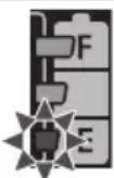
Overheat warning

Off (normal operation)

Illuminated: Overheat (motor)

Flashing: Overheat (battery)
Indicates operation has been halted due to motor or battery overheating.
To protect the motor or battery, be sure to note the following when carrying out this operation.
- If the motor or battery becomes hot, the protection function will be activated and the motor or battery will stop operating. The overheat warning lamp on the control panel illuminates or flashes when this feature is active.
- If the overheating protection feature activates, allow the tool to cool thoroughly (at least 30 minutes). The tool is ready for use when the overheat warning lamp goes out.
- Avoid using the tool in a way that causes the overheating protection feature to activate repeatedly.
- If the tool is operated continuously under high-load conditions or if it is used in hot-temperature conditions (such as during summer), the overheating protection feature may activate frequently.
- If the tool is used in cold-temperature conditions (such as during winter) or if it is frequently stopped during use, the overheating protection feature may not activate.
The performance of the EY9L42 deteriorates significantly at and below 10^ C due to work conditions and other factors.
Battery Level Indicator
Press the battery level button.
Battery level indicator shows battery level in three levels while pressing the button. It shifts to Impact power mode when release the button.
NOTE:
The indicator will not show the battery level even the button is pressed in the following cases.
- The main unit is powered off.
- Just after attaching the battery pack
- The main unit or battery level button is not operated for approx. five minutes. Press the battery level button again after depressing the trigger switch.
- If the battery temperature is high, stop the operation and wait until the battery temperature is low.
| Indicator Battery status | ||
 | 3 lamps illuminated | Charged enough |
 | 2 lamps illuminated | Approx. 60% remaining |
 | One lamp illuminated | Battery level is low.Need to be charged soon |
 | 3 lamps flashing | Empty Need to be charged immediately |
EN
Battery level indication is just guide. The indication may change due to the condition of battery or ambient temperature.
Excessive (complete) discharging of lithium ion batteries shortens their service life dramatically. The driver includes a battery protection feature designed to prevent excessive discharging of the battery pack.
[Battery Pack]
For Appropriate Use of Battery Pack [Fig.6]
- The rechargeable batteries have a limited life.
- For optimum battery life, store the Li-ion battery pack following use without charging it.
- When operating the battery pack, make sure the work place is well ventilated.
For safe use
- The battery pack is designed to be installed by proceeding two steps for safety. Make sure the battery pack is installed properly to the main unit before use.
- If the battery pack is not connected firmly when the switch is switched on, the overheat warning lamp and the battery low warning lamp will flash to indicate that safe operation is not possible, and the main unit will not rotate normally. Connect the battery pack into the unit of the tool until the red or yellow label disappears.
- Only use rechargeable battery packs for Panasonic rechargeable tools. Do not use modified battery packs (including battery packs which have been disassembled and parts replaced).
- Do not use deteriorated battery packs. There is a risk of the generation of heat, ignition and explosion.
- If a battery pack leaks fluid, cease use, keep away from open flames, and return it to the store immediately.
- Attach the battery pack by sliding until the yellow and red labels are no longer visible, and check that it does not fall out of place.
- Failure to do so may result in scalding.
- The usage temperature range for lithium ion battery packs is 0 to 40 degrees.
- Use of battery packs cooled to below zero, such as in colder northern areas, may result in abnormal operation of the device. In such cases, leave the battery pack in a location of 10 degrees or more for one hour or more before use, and only use the device after the battery pack has warmed up.
[Battery Charger]
Charging
CAUTION:
1) If the temperature of the battery pack falls approximately below -10^ ( 14^ ), charging will automatically stop to prevent degradation of the battery.
2) The ambient temperature range is between 0^ C ( 32^ F) and 40^ C ( 104^ F).
If the battery pack is used when the battery temperature is below 0^ C ( 32^ F), the tool may fail to function properly.
3) Use the charger at temperatures between 0^ C and 40^ C, and charge the battery at a temperature similar to that of the battery itself. (There should be no more than a 15^ C difference between the temperatures of the battery and the charging location.)
4) When charging a cool battery pack (below 0^ C ( 32^ F)) in a warm place, leave the battery pack at the place and wait for more than one hour to warm up the battery to the level of the ambient temperature.
5) Cool down the charger when charging more than two battery packs consecutively.
6) Do not insert your fingers into contact hole, when holding charger or any other occasions.
7) To prevent the risk of fire or damage to the battery charger.
- Do not cover vent holes on the charger and the battery pack.
- Unplug the charger when not in use.
8) Store the charger between 0 and 40 degrees, and charge the battery pack at a temperature close to the storage temperature.
- If the battery pack is charged while at a temperature below 0 degrees, a full charge will give only around 50% of a normal charge. Commence charging after 1 hour or more at the prescribed temperature.
9) Do not charge in a poorly ventilated place.
10) Do not cover the battery pack or charger with a cloth or the like while charging is in progress.
NOTE:
Your battery pack is not fully charged at the time of purchase. Be sure to charge the battery before use.
How to charge
- Plug the charger into the AC outlet.
NOTE:
Sparks may be produced when the plug is inserted into the AC power supply, but this is not a problem in terms of safety.
- Connect the battery pack firmly into the charger.
1 Line up the alignment marks and place the battery onto the dock on the charger.
NOTE:
Not all battery packs display the alignment mark (Q) (on page 2).
2 Slide forward in the direction of the arrow. [Fig.7]
- During charging, the charging lamp will be lit. When charging is completed, an internal electronic switch will automatically be triggered to prevent overcharging.
- Charging will not start if the battery pack is hot (for example, immediately after heavy-duty operation).
The orange standby lamp will be flashing until the battery cools down. Charging will then begin automatically.
-
The charge lamp (green) will flash slowly once the battery is approximately 80% charged.
-
When charging is completed, the charging lamp in green color will turn off.
-
If the temperature of the battery pack is 0^ C or less, charging takes longer to fully charge the battery pack than the standard charging time.
Even when the battery is fully charged, it will have approximately 50% of the power of a fully charged battery at normal operating temperature.
-
Consult an authorized dealer if the charging lamp (green) does not turn off.
-
If a fully charged battery pack is inserted into the charger again, the charging lamp lights up. After several minutes, the charging lamp in green color will turn off.
-
Remove the battery pack while the battery pack release button is held up.
[Fig.7]


Turn off Illuminated

Flashing
Battery Recycling
ATTENTION:
For environmental protection and recycling of materials, be sure that it is disposed of at an officially assigned location, if there is one in your country.
Information for Users on Collection and Disposal of Old Equipment and used Batteries

natural_image
Symbol of a trash bin with crossed lines indicating no waste or discharge (no text or labels)These symbols on the products, packaging, and/or accompanying documents mean that used electrical and electronic products and batteries should not be mixed with general household waste.
For proper treatment, recovery and recycling of old products and used batteries, please take them to applicable collection points, in accordance with your national legislation and the Directives 2012/19/EC and 2006/66/EC.
By disposing of these products and batteries correctly, you will help to save valuable resources and prevent any potential negative effects on human health and the environment which could otherwise arise from inappropriate waste handling.
For more information about collection and recycling of old products and batteries, please contact your local municipality, your waste disposal service or the point of sale where you purchased the items.
Penalties may be applicable for incorrect disposal of this waste, in accordance with national legislation.

[For business users in the European Union]
If you wish to discard electrical and electronic equipment, please contact your dealer or supplier for further information.
[Information on Disposal in other Countries outside the European Union]
These symbols are only valid in the European Union. If you wish to discard these items, please contact your local authorities or dealer and ask for the correct method of disposal.
IV. MAINTENANCE
- Use only a dry, soft cloth for wiping the unit.
Do not use a damp cloth, thinner, benzine, or other volatile solvents for cleaning.
- In the event that the inside of the tool or battery pack is exposed to water, drain and allow to dry as soon as possible. Carefully remove any dust or iron filings that collect inside the tool. If you experience any problems operating the tool, consult with a repair shop.
V. OPTIONAL ACCESSORIES
- Use only suitable size of bit.
- Panasonic original optional quick change chuck (EY9HX131E).
Chuck Size: 6.35 mm hex
EY9HX131E

CAUTION:
Do not use the unit to drill holes into wood and metal.
VI. APPENDIX
MAXIMUM RECOMMENDED CAPACITIES
| Model No. EY75A7 EY75A8 | |||
| Screw driving | Wood screw Φ 3.5 | mm – Φ 9.5 mm | — |
| Self-drilling screw Φ | 3.5 mm – Φ 6 mm | ||
| Bolt fasten-ing | Standard bolt M6 – | M16 M10 – M20 | |
| High tensile bolt M6 – | M12 M10 – M16 | ||
WARRANTY SUPPLEMENT
- The breakdown and damage caused by usage consistent for a long time (e.g.: factory work on the assembly line, etc.) is out of warranty.
- In the event that the inside of the tool or battery pack is exposed to water, drain and allow to dry as soon as possible. Carefully remove any dust or iron filings that collect inside the tool. If you experience any problems operating the tool, consult with a repair shop.
VII. SPECIFICATIONS
NOTE: Weight indication
Greater than or equal to 1 kg: indicated by 0.05 kg.
Less than 1 kg: indicated by 0.01 kg.
MAIN UNIT
| Model No. EY75A7 EY75A8 | |||||
| Motor voltage 14.4 V DC 18 V DC | 14.4 V DC 1 | 18 V DC | |||
| No load speed[min-1(rpm)] | Soft mode | 0 – 950 0 – 1000 | |||
| Medium mode | 0 – 1450 0 – 1500 | ||||
| Hard mode | 0 – 2500 0 – 2300 | 0 – 2500 | |||
| Self-drilling screw mode | 0 – 2500 — | ||||
| Maximum torque | 155 N·m(15.8 kgf·m) | 160 N·m(16.3 kgf·m) | 260 N·m(26.5kgf·m) | 280 N·m(28.6 kgf·m) | |
| Impact per minute[min-1(ipm)] | Soft mode | 0 – 1900 | |||
| Medium mode | 0 – 2900 | ||||
| Hard mode | 0 – 3100 0 – 3400 | 0 – 3600 | |||
| Self-drilling screw mode | 0 – 1200 — | ||||
| Overall length 118 mm 143 mm | |||||
| WeightWith battery pack: | EY9L45 | 1.55 kg— | 1.65 kg— | ||
| EY9L50 | — 1.70 | kg— 1.80 kg | |||
| EY9L51 | — 1.70 | kg— 1.80 kg | |||
| EY9L52 | — 1.45 | kg— 1.55 kg | |||
| EY9L53 | — 1.50 | kg— 1.60 kg | |||
| EY9L54 | — 1.70 | kg— 1.80 kg | |||
| Noise, Vibration See the included sheet | |||||
ONLY FOR U. K.
VIII. CAUTION FOR AC MAINS LEAD
FOR YOUR SAFETY PLEASE READ THE FOLLOWING TEXT CAREFULLY
This appliance is supplied with a moulded three pin mains plug for your safety and convenience. A 5 amp fuse is fitted in this plug.
Should the fuse need to be replaced please ensure that the replacement fuse has a rating of 5 amp and that it is approved by ASTA or BSI to BS1362.
Check for the ASTA mark 📀 or the BSI mark 🌐 on the body of the fuse.
If the plug contains a removable fuse cover you must ensure that it is refitted when the fuse is replaced.
If you lose the fuse cover the plug must not be used until a replacement cover is obtained.
A replacement fuse cover can be purchased from your local Panasonic Dealer.
CAUTION:
IF THE FITTED MOULDED PLUG IS UNSUITABLE FOR THE SOCKET OUTLET IN YOUR HOME THEN THE FUSE SHOULD BE REMOVED AND THE PLUG CUT OFF AND DISPOSED OF SAFELY. THERE IS A DANGER OF SEVERE ELECTRICAL SHOCK IF THE CUT OFF PLUG IS INSERTED INTO ANY 13 AMP SOCKET.
How to replace the fuse
The location of the fuse differs according to the type of AC mains plug (figures A and B).
Confirm the AC mains plug fitted and follow the instructions below. Illustrations may differ from actual AC mains plug. Open the fuse cover with a screwdriver and replace the fuse and close or attach the fuse cover.


natural_image
Symbol of a trash bin crossed out by two diagonal lines, with a blank rectangular base below (no text or symbols)natural_image
Symbol of a trash bin crossed with no visible text or labelsnatural_image
Symbol of a trash bin with crossed lines indicating no waste or discharge, and a solid black rectangle below (no text or labels)flowchart
graph LR
    A["Uit (normale werking)"] --> B["Verlicht: Oververhitting (motor)"]
    B --> C["Knippert: Oververhitting (accu)"]
V. OPTIONELE ACCESSOIRES
natural_image
Symbol of a trash bin crossed with no text or labels, accompanied by a black rectangular block below (no text or symbols present)Overophed- ning (motor)

Blinker:
Overophed- ning (batteri)
natural_image
Symbol of a trash bin crossed with no text or labels, accompanied by a black rectangle below (no readable text or symbols)natural_image
Symbol of a trash bin crossed with no text or numbers, representing waste sorting or disposal (no text present)Lyser: Overopphe-ting (motor)
Blinker: Overopphe-ting (batteri)
natural_image
Symbol of a trash bin crossed with no text or numbers, representing waste sorting or disposal (no text present)Slike symboler på produkter, emballasje, og/eller på medfølgende dokumenter betyr at brukte elektriske/elektroniske produkter og batterier ikke må blandes med vanlig husholdningsavfall.
natural_image
Symbol of a trash bin with crossed lines indicating no waste or discharge, and a solid black rectangle below (no text or labels)natural_image
Symbol of a trash bin crossed out by two crossed lines, with a solid black rectangle below (no text or labels)Importer for Turkey:
Panasonic Eco Solutions Elektnik San Tic A.Ş
Abdurrahmangazi Mah. Ebubekir Cad. No: 44
natural_image
Symbol of a trash bin crossed out by two crossed lines, with a solid black rectangle below (no text or labels)natural_image
Symbol of a trash bin crossed out by two crossed lines, with a solid black rectangle below (no text or labels)V. VOLITELNÉ PŘÍSLUŠENSTVÍ
natural_image
Symbol of a trash bin with crossed lines indicating no waste or discharge, and a solid black rectangle below (no text or labels)natural_image
Symbol of a trash bin crossed out by two crossed lines, with a solid black rectangle below (no text or labels)natural_image
Symbol of a trash bin crossed with no visible text or labelsPanasonic Testing Centre
Panasonic Europe Ltd. Hamburg office
Winsbergring 15,
22525 Hamburg,
Germany
Panasonic Corporation
1006,Kadoma,Osaka 571-8501,Japan
http://www.panasonic.com


- [Fig.6]
- Original instructions: English Translation of the original instructions: Other languages
- ADDITIONAL SAFETY RULES
- WARNING
- ASSEMBLY
- NOTE:
- Attaching or Removing Bit
- CAUTION:
- Attaching or Removing Socket [Fig.2]
- Attaching or Removing Battery Pack
- OPERATION
- WARNING!
- [Main Body]
- CAUTION
- Switch and Forward/Reverse Lever Operation [Fig.4]
- Changing the Belt Hook Location Side [Fig.5]
- Impact Power Mode Select
- [EY75A7]
- [EY75A8]
- Only for EY75A7
- Self-drilling screw
- LED Light
- CAUTION: DO NOT STARE INTO BEAM.
- Overheat warning
- Battery Level Indicator
- EN
- [Battery Pack]
- For Appropriate Use of Battery Pack [Fig.6]
- For safe use
- [Battery Charger]
- Charging
- How to charge
- Battery Recycling
- ATTENTION:
- Information for Users on Collection and Disposal of Old Equipment and used Batteries
- [For business users in the European Union]
- [Information on Disposal in other Countries outside the European Union]
- MAINTENANCE
- OPTIONAL ACCESSORIES
- EY9HX131E
- APPENDIX
- WARRANTY SUPPLEMENT
- SPECIFICATIONS
- ONLY FOR U. K.
- CAUTION FOR AC MAINS LEAD
- FOR YOUR SAFETY PLEASE READ THE FOLLOWING TEXT CAREFULLY
- How to replace the fuse
- OPTIONELE ACCESSOIRES
- Importer for Turkey:
- VOLITELNÉ PŘÍSLUŠENSTVÍ
Brand : PANASONIC
Model : EY75A8
Category : Screwdriver