
EY6803 - Screwdriver PANASONIC - Free user manual and instructions
Find the device manual for free EY6803 PANASONIC in PDF.


| Type | Cordless Screwdriver |
| Brand | Panasonic |
| Model | EY6803 |
| Power Source | Rechargeable Ni-MH Battery |
| Voltage | 14.4 V |
| Battery Capacity | 2.0 Ah |
| Max Torque | 30 Nm |
| Speed Range | 0 - 600 rpm (Variable Speed) |
| Chuck Type | 1/4" Hex Quick-Release |
| Weight (with battery) | 1.2 kg |
| Dimensions | 200 x 60 x 80 mm |
| Features | Electronic Brake, LED Work Light, Ergonomic Handle, Belt Clip |
| Safety Features | Overload Protection, Lock-on Button |
| Included Accessories | Battery, Charger, Bit Holder, Carrying Case |
| Usage | Screwing and Light Drilling |
| Maintenance | Keep vents clean, recharge after use, store in dry place |
| Reparability | Replaceable battery pack and carbon brushes |
Frequently Asked Questions - EY6803 PANASONIC
User questions about EY6803 PANASONIC
0 question about this device. Answer the ones you know or ask your own.
Ask a new question about this device
Download the instructions for your Screwdriver in PDF format for free! Find your manual EY6803 - PANASONIC and take your electronic device back in hand. On this page are published all the documents necessary for the use of your device. EY6803 by PANASONIC.
USER MANUAL EY6803 PANASONIC
natural_image
Line drawing of a handheld electric shaver device (no text or symbols)Before operating this unit, please read these instructions completely and save this manual for future use. Vor Inbetriebnahme des Gerätes die Betriebsanleitung bitte gründlich durchlesen und diese Broschüre zum späteren Nachschlagen sorgfältig aufbewahren. Lire entièrement les instructions suivantes avant de faire fonctionner l'appareil et conserver ce mode d'emploi à des fins de consultation ultérieure. Prima di usare questo apparecchio, leggere completamente queste istruzioni e conservare il manuale per usi futuri. Lees deze gebruiksaanwijzing aandachtig door voor u het apparaat in gebruik neemt en bewaar de gebruiksaanwijzing voor eventuele naslag. Antes de usar este aparato por primera vez, lea todas las instrucciones de este manual y guarde el manual para poderlo consultar en el futuro. Gennemlæs denne betjeningsvejledning før brugen og gem den til fremtidig brug. Läs igenom hela bruksanvisningen innan produkten tas i bruk. Spara bruksanvisningen för senare användning. Før enheten tas i bruk, vennligst les disse alle anvisningene og oppbevar bruksanvisningen for senere bruk. Lue ohjeet huolella ennen laitteen käyttöönottoa ja säilytä tämä käyttöohje tallessa tulevaa tarvetta varten. Перед эксплуатацией данного устройства, пожалуйста, полностью прочите данную инструкцию и сохраните данное руководство для использования в будущем. Перед екплуатацією даного пристрою, будь ласка, повністю прочитайте дану інструкцію і збережіть її для використання у майбутньому.
Index/Index/Index/Indice/Index/Indice/Indeks/Index/Indeks/Hakemisto/Индекс/Индекс
English: Page 4
Deutsch: Seite 12
Français: Page 20
Italiano: Pagina 28

(J)

(K)

(L)

(M)
| (A) | ChuckFutterMandrinMandrinoBoorkopPortabrocaBorepatronChuckChuckIstukanvoiteluЗажимной патронЗатискний патрон | (B) | Hammering/drilling switching leverUmschalter Schlagbohren/SchrauberCommutateur martelage/perforationLeva di commutazione martellatura/perforazioneKeuzeschakelaar normaal boren/klopborenPalanca de conmutación de martillo/taladroHamrings/borings omskiftningsgrebOmkopplare mellan slagborr/vanlig borrSlag/bor omskifterVasaran/poran kytkentävipuРычаг переключения долбления/сверленияВажіль перемикання довбання/свердління | |||
| (C) | Forward/reverse leverVorwärts/RückwärtshebelLevier d'inversion marche avant/marche arrièreLeva di avanzamento/inversioneLinks/rechtsschakelaarPalanca de avance/marcha atrásGreb til forlæns/baglæns retningRiktningsomkopplareForover-/bakoverbryterEteenpäin/taaksepäin vipuРычаг переключения вперед/назадВажіль перемикання вперед/назад | (D) | Variable speed control triggerElektronikschalterGâchette de commande de vitesseGrilletto di controllo velocità variabileStartschakelaar met variabele toerentalregelingDisparador del control de velocidad variableKontroludlöser for variabel hastighedAvtryckare med variabel varvtalsregleringHovedbryter, trinnlösNopeudensäätökytkinПереключатель регулировки переменной скоростиПеремикач регулювання змінної швидкості | |||
| (E) | Battery pack release buttonAkku-EntriegelungsknopfBouton de libération de batterie autonomeTasto di rilascio pacco batteriaAccu-ontgrendeltoetsBotón de liberación de bateríaUdløserknap til batteripakningFrigöringsknapp för batteriUtløserknapp for batteripakkeAkkupaketin irrotuspainikeКнопка освобождения батарейного блокаКнопка вивільнення батарейного блоку | (F) | Battery pack (EY9201)Akku (EY9201)Batterie autonome (EY9201)Pacco batteria (EY9201)Accu (EY9201)Batería (EY9201)Batteripakning (EY9201)Batteri (EY9201)Batteripakke (EY9201)Akku (EY9201)Батарейный блок (EY9201)Батарейний блок (EY9201) | |||
| (G) | Bit holder (inside of the body)Einsatzhalter (im Maschinenkörper)Porte-mèche (intérieur du corps)Portabit (all'interno della struttura)Bithouder (geïntegreerd in de behuizing)Soporte de broca (en el interior del cuerpo)Bitholder (indvendig i værktøjet)Bitshållare (inuti höljet)Bitholder (inne i maskinhuset)Terän pidin (rungon sisällä)Отсек для хранения насадок (внутри корпуса)Відсік для зберігання насадок (всередині корпусу) | (H) | Bit adapter holderEinsatzadapterhalterPorte-adaptateur de mècheAdattatore di portabitBitadapterhouderSoporte de adaptador de brocaBoradapterholderHållare för verktygsspetsadapterHolderstykke for bit-tilpasningsstykkeTerän sovittimen pidinОтсек хранения адаптера для насадокВідсік зберігання адаптера для насадок | |||
| (I) | LED lightLED-LeuchteLumière DELLuce LEDLED-lampjeLuz indicadoraLED-lysLED-IjusLED lysLED-valoСветодиодная подсветкаСвітлодіодне підсвічування | (J) | Battery charger (EY0110)Ladegerät (EY0110)Chargeur de batterie (EY0110)Caricabatteria (EY0110)Acculader (EY0110)Cargador de baterías (EY0110)Batterioplader (EY0110)Batteriladdare (EY0110)Batterilader (EY0110)Akkulaturi (EY0110)Зарядное устройство (EY0110)Зарядний пристрій (EY0110) | (K) | GreaseSchmierungGraisseLubrificanteVetGrasaSmørefedtFettSmørefettRasvaСмазкаМастило | |
| (L) | Bit adapter (EY9HX403)Einsatzadapter (EY9HX403)Adaptateur de mèche (EY9HX403)Portabit (EY9HX403)Bitadapter (EY9HX403)Adaptador de broca (EY9HX403)Boradapter (EY9HX403)Verktygsspetsadapter (EY9HX403)Bitholderen (EY9HX403)Bitsi adapteri (EY9HX403)Адаптер для насадок (EY9HX403)Адаптер для насадок (EY9HX403) | (M) | Shoulder strapSchulterriemenDragonneCinghia da spallaSchouderriemCorrea al hombroSkulderremAxelremSkulderbelteOlkahihnaПлечевой ременьПлечовий ремінь | |||
Read "Safety Instructions" booklet and the following before using.
I. ADDITIONAL SAFETY RULES
1) Wear ear protection. Exposure to noise can cause hearing loss.
2) Be aware that this tool is always in an operating condition, since it does not have to be plugged into an electrical outlet.
3) When drilling into walls, floors, etc., "live" electrical wires may be encountered. DO NOT TOUCH THE CHUCK OR ANY FRONT METAL PARTS OF THE TOOL! Hold the tool only by the plastic handle to prevent electric shock in case you drill into a "live" wire.
4) If the bit becomes jammed, immediately turn the trigger switch off to prevent an overload which can damage the battery pack or motor. Use reverse motion to loosen jammed bits.
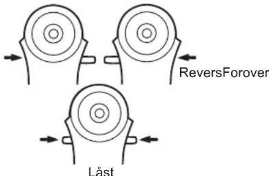
5) Do NOT operate the Forward/Reverse lever when the trigger switch is on. The battery will discharge rapidly and damage to the unit may occur.
6) When storing or carrying the tool, set the Forward/Reverse lever to the center position (switch lock).
7) Do not strain the tool by holding the speed control trigger halfway (speed control mode) so that the motor stops. The protection circuit will activate and may prevent speed control operation. If this happens, release the speed control trigger and squeeze again for normal operation.
8) Be careful not to get dust inside the chuck.
9) Do not touch the rotating parts to avoid injury.
10) Do not use the tool continuously for a long period of time. Stop using the tool from time to time to avoid temperature rise and heat overload of the motor.
11) Do not drop the tool.
| Symbol | Meaning |
| V Volts | |
| --- | Direct current |
| n_0 | No load speed |
| .../min | Revolutions orreciprocations per minutes |
 | Rotation with hammering |
 | Rotation only |
II. OPERATION
CAUTION:
Use of a concrete drill bit larger than the recommended size may cause damage to the driver.
Chuck
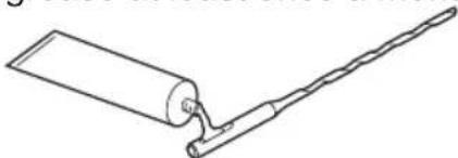
NOTE: Grease for bit Grease the oval indentation on the bit with the supplied grease at least once a month.
natural_image
Line drawing of a mechanical tool or tool with a cylindrical component and a straight rod (no text or symbols)1. To insert the bit
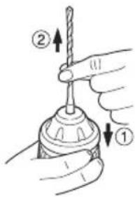
1-1. Insert a bit into the mounting hole, and turn it slightly to locate an engaged position.
1-2. At the engaged position, push the bit as far as it goes. Make sure that the bit is fixed by pulling it.

2. To remove the bit
2-1. Depress the chuck cover and pull the bit.
Bit adapter
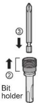
Use a bit adapter (standard) and bit.
- Remove the bit adapter from the bit adapter holder on the main unit.
- Pull the bit holder. (②)
- Insert the bit. (③)
- Make sure the bit is inserted firmly by pulling it lightly.
- Insert the bit adapter into the mounting hole and turn to locate an engaged position.
- At the engaged position, push in as far as it goes.
• Make sure it does not move by pulling it lightly.
Forward/Reverse Lever

- Be sure to set the switch in the center to lock it after use.
- Operate the Forward/Reverse lever after the motor rotation is completely stopped.
Hammering/Drilling Switching Lever
NOTE: Operate the mode change after the motor rotation is completely stopped.
| Position of switching lever | Action mode | Operation |
 | Rotation with hammering | Concrete Drilling, Block Drilling |
 | Rotation only | Screw Fastening, Metal Drilling |
Clutch Torque Setting
Adjust the torque to one of the 5 clutch settings or “#” position.
CAUTION:
Test the setting before actual operation.
Set the scale at this mark (◀).

natural_image
Technical line drawing of a mechanical device with a rotating knob and adjustment knob (no text or symbols)Variable Speed Control Trigger
To set the center of a hole, pull the trigger slightly to start the drill rotation slowly. The more the speed control trigger is pulled, the higher the speed becomes.
LED Light
CAUTION:
- The built-in LED light is designed to illuminate the small work area temporarily.
- Do not use it as a substitute for a regular flashlight, since it does not have enough brightness.
natural_image
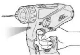
Line drawing of a hand using a power tool with a flashlight (no text or symbols)Depress the trigger switch, then LED light turns on. When the trigger switch is released, the light turns off automati-
cally. The light illuminates with very low current, and it does not adversely affect the performance of the tool during use or its battery capacity.
This product has the built-in LED light. This product is classified into "Class 1 LED Product" to EN 60825-1
Class 1 LED Product
Caution : DO NOT STARE INTO BEAM.
Installing the Shoulder Strap CAUTION:
• Install the shoulder strap firmly to the main unit of the tool and check the length of the strap before use.
- Check the condition of the strap and do not use if it is cut or torn etc.
There is a risk of injury or damage if used while improperly installed.
- Please wear the shoulder strap securely on the shoulder.
There is a risk of injury or damage if it is accidentally dropped.
- Pass the strap through the strap holders. (①)
- Pass the strap through the buckles and adjust the length. (②)
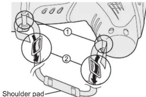
- The shoulder strap can be adjusted according to the individual.
- Adjust the shoulder pad to the shoulder.
- Pull the shoulder strap to make sure it is firmly attached to the main unit of the tool.
For Appropriate Use of Battery Pack
Ni-MH Battery Pack (EY9201)
- Charge the Ni-MH battery fully before storage in order to ensure a longer service life.
- The ambient temperature range is between 0°C (32°F) and 40°C (104°F). If the battery pack is used when the battery temperature is below 0°C (32°F), the tool may fail to function properly. In that case, charge the battery until charging is completed for appropriate functioning of the battery.
- When battery pack is not in use, keep it away from other metal objects like: paper clips, coins, keys, nails, screws, or other small metal objects that can make a connection from one terminal to another. Shorting the battery terminals together may cause sparks, burns or a fire.
- When operating the battery pack, make sure the work place is well ventilated.
Battery Pack Life
The rechargeable batteries have a limited life. If operation time becomes extremely short after recharging, replace the battery pack with a new one.
NOTE: • Use under extremely hot or cold conditions will reduce operating capacity per charge.
Battery Recycling
For environmental protection and recycling of materials, be sure that it is disposed of at an officially assigned location, if there is one in your country.
Battery Charger
NOTE: Charge a new battery pack, or a battery pack that has not been used for a prolonged time, for about 24 hours to bring the battery up to full charge.
Battery charger (EY0110)
- Plug the charger into the AC outlet.
NOTE: Sparks may be produced when the plug is inserted into the AC power supply, but this is not a problem in terms of safety.
- Insert the battery pack firmly into the charger.
Battery pack

- During charging, the charging lamp will be lit.
When charging is completed, an internal electronic switch will automatically be triggered to prevent overcharging.
- Charging will not start if the battery pack is warm (for example, immediately after heavy-duty operation). The orange standby lamp will be lit until the battery cools down. Charging will then begin automatically.
-
When charging is completed, the charging lamp will start flashing quickly in green color.
-
When in any of the conditions that battery pack is too cool, or the battery pack has not been used for a long time, the charging lamp is lit. In this case charging takes longer to fully charge the battery pack, than the standard charging time.
- If a fully charged battery pack is inserted into the charger again, the charging lamp lights up. After several minutes, the charging lamp may flash quickly to indicate the charging is completed.
- If the charging lamp does not light immediately after the charger is plugged in, or if after the standard charging time the lamp does not go off, consult an authorized dealer.
NOTE: • When charging a cool battery pack (below 5°C (41°F)) in a warm place, leave the battery pack at the place and wait for more than one hour to warm up the battery to the level of the ambient temperature. Otherwise battery pack may not be fully charged.
• Cool down the charger when charging more than two battery packs consecutively.
- Do not insert your fingers into contact hole, when holding charger or any other occasions.
CAUTION:
To prevent the risk of fire or damage to the battery charger.
- Do not use power source from an engine generator.
- Do not cover vent holes on the charger and the battery pack.
- Unplug the charger when not in use.
LAMP INDICATIONS

flowchart
graph TD
    A["●"] --> B["Red Flashing"]
    A --> C["Red Lit"]
    A --> D["Green Flashing Quickly"]
    E["●"] --> F["Orange Lit"]
    E --> G["Orange Flashing"]
    H["Charger is plugged into the AC outlet. Ready to charge."] --> I["→"]
    J["Now charging."] --> K["→"]
    L["Charging is completed."] --> M["→"]
    N["Battery pack is warm. Charging will begin when temperature of battery pack drops."] --> O["→"]
    P["Charging is not possible. Clogged with dust or malfunction of the battery pack."] --> Q["→"]
Information on Disposal for Users of Waste Electrical & Electronic Equipment (Private Households)

natural_image
Symbol of a trash bin crossed with a diagonal line, no text or numbers presentThis symbol on the products and/or accompanying documents means that used electrical and electronic products should not be mixed with general household waste.
For proper treatment, recovery and recycling, please take these products to designated collection points, where they will be accepted on a free of charge basis. Alternatively, in some countries you may be able to return your products to your local retailer upon the purchase of an equivalent new product.
Disposing of this product correctly will help to save valuable
resources and prevent any potential negative effects on human health and the environment which could otherwise arise from inappropriate waste handling.
Please contact your local authority for further details of your nearest designated collection point.
Penalties may be applicable for incorrect disposal of this waste, in accordance with national legislation.
For Business Users in the European Union
If you wish to discard electrical and electronic equipment, please contact your dealer or supplier for further information.
Information on Disposal in Other Countries Outside the European Union
This symbol is only valid in the European Union.
If you wish to discard this product, please contact your local authorities or dealer and ask for the correct method of disposal.
III. MAINTENANCE
Use only a dry, soft cloth for wiping the unit. Do not use a damp cloth, thinner, benzine, or other volatile solvents for cleaning.
IV. ACCESSORIES
CAUTION:
To prevent the risk of injury, only use accessory or attachment for its stated purpose.
Bit adapter
•EY9HX403
Drill chuck (Optional accessory)
•EY9HX400
Hammer chuck (Optional accessory)
•EY9HX401
Battery pack
•EY9201 (Ni-MH)
Battery charger
•EY0110
If you need any assistance for more details regarding these accessories, ask your local service center.
V. USAGE SUGGESTION
- If there isn't enough force pushing down on the bit, the hammer may not be able to blow in hammering mode.
This is to prevent the hammering mode from operating with no load. Press down harder on the bit to engage the hammer and cause it to blow.
Always be sure to press down with enough force when working.
- In winter or in other situations where the temperature of the unit is low (5°C or below), the blow of the hammering mode may be weaker than normal at the beginning stage.
This is because the grease becomes stiffer in low temperatures, increasing friction. If this should happen, operating hammering mode with no load for approximately 30 seconds and repeat this 3 times. This will restore its blowing power.
VI. SPECIFICATIONS
MAIN UNIT (EY6803)
| Maximum drilling diameter | Concrete | 10 mm (25/64") *12.5 mm (15/32")*For work that can be completed with one battery pack. |
| Steel | 13 mm (33/64") | |
| Motor voltage 12 V DC | ||
| Speed at no load (RPM) 0 | -1000 /min (rpm) | |
| Blows rate per minute (BPM) 0 | -4000 /min (bpm) | |
| Weight (with battery pack) | 2.5 kg (5.5 lbs) | |
| Dimensions (L×W×H) | 249×257×64 mm (10"×10-1/8"×2-1/2") | |
GUIDELINE TABLE
- Select the torque for fastening screws with the clutch handle.
• Guide for the selection of torque
Depending on the job, adjustments are possible in five levels by approximately 1 Nm (10 kgf-cm) increments.
| Setting Torque | Guide Depending on Material | ||||
| Concrete Block | |||||
| (A) (B) | (A) (B) | ||||
| Fastening Screws | 1 Approximately 1.5 Nm (15 kgf-cm) | ● | |||
| 2 Approximately 2.5 Nm (25 kgf-cm) | ● | ||||
| 3 Approximately 3.4 Nm (35 kgf-cm) | ● | ● | ● | ||
| 4 Approximately 4.4 Nm (45 kgf-cm) | ● | ● | ● | ||
| 5 Approximately 5.4 Nm (55 kgf-cm) | ● | ||||
| Drilling Holes (Drill Mark) Approximately 8.3 Nm (85 kgf-cm) Drilling holes in metal | |||||
(A) For fastening screws into plastic anchor which requires dia. 6.0 mm (1/4") prehole in the concrete.
(B) For directly fastening screws into concrete (like topcon) with dia. 3.5 mm (1/8") prehole.
NOTE: This is only a rough guide. Required torque is different depending on the shape, material, and application of the screws.
Set according to the work environment of the site.
BATTERY PACK (EY9201 is included with shipment.)
| Model EY9201 | EY9200 | EY$106 | EY910 | 1 | EY9001, | EY9006 | |
| Battery voltage | 12 V DC (1.2 V × 10 cells) | ||||||
| Storage battery | Ni-MH Battery | Ni-Cd Battery | |||||
| Capacity | 3.5 Ah | 3.0 Ah | 2.0 Ah | 1.7 Ah | 1.2 Ah | ||
BATTERY CHARGER
| Model | EY0110 | ||||||
| Rating | See the rating plate on the bottom of the charger. | ||||||
| Weight | 0.78 kg (1.72 lbs) | ||||||
| Charging time | 7.2 V | 9.6 V | 12 V | 15.6 V | 18 V | 24 V | |
| 1.2 Ah | EY9065 | EY9080 | EY9001 | ||||
| EY9066 | EY9086 | EY9006 | |||||
| 20 min. | |||||||
| 1.7 Ah | EY9180 | EY9101 | |||||
| EY9182 | |||||||
| 25 min. | |||||||
| 2.0 Ah | EY9168 | EY9106 | EY9136 | EY9116 | |||
| 30 min. | 30 min. | EY9117 | |||||
| 3.0 Ah | EY9200 | EY9230 | EY9210 | ||||
| 45 min. | 90 min. | ||||||
| 3.5 Ah | EY9201 | EY9231 | EY9251 | ||||
| 55 min. | 65 min. | ||||||
NOTE: This chart may include models that are not available in your area. Please refer to the catalogue.
ONLY FOR U. K.
VII. ELECTRICAL PLUG INFORMATION
FOR YOUR SAFETY PLEASE READ THE FOLLOWING TEXT CAREFULLY
This appliance is supplied with a moulded three pin mains plug for your safety and convenience.
A 3 amp fuse is fitted in this plug.
Should the fuse need to be replaced please ensure that the replacement fuse has a rating of 3 amp and that it is approved by ASTA or BSI to BS1362.
Check for the ASTA mark or the BSI mark on the body of the fuse.
If the plug contains a removable fuse cover you must ensure that it is refitted when the fuse is replaced.
If you lose the fuse cover the plug must not be used until a replacement cover is obtained.
A replacement fuse cover can be purchased from your local Panasonic Dealer.
IF THE FITTED MOULDED PLUG IS UNSUITABLE FOR THE SOCKET OUTLET IN YOUR HOME THEN THE FUSE SHOULD BE REMOVED AND THE PLUG CUT OFF AND DISPOSED OF SAFELY.
THERE IS A DANGER OF SEVERE ELECTRICAL SHOCK IF THE CUT OFF PLUG IS INSERTED INTO ANY 13 AMP SOCKET.
If a new plug is to be fitted please observe the wiring code as shown below.
If in any doubt please consult a electrician.
IMPORTANT:
The wires in this mains lead are coloured in accordance with the following code:
Blue: Neutral
Brown: Live
As the colours of the wire in the mains lead of this appliance may not correspond with the coloured markings identifying the terminals in your plug, proceed as follows. The wire which is coloured BLUE must be connected to the terminal in the plug which is marked with the letter N or coloured BLACK.
The wire which is coloured BROWN must be connected to the terminal in the plug which is marked with the letter L or coloured RED. Under no circumstances should either of these wires be connected to the earth terminal of the three pin plug, marked with the letter E or the Earth Symbol 12 .
How to replace the fuse: Open the fuse compartment with a screwdriver and replace the fuse and fuse cover if it is removable.

This apparatus was produced to BS800.
qualified
natural_image
Simple line drawing of a tool or device with a cylindrical component and a straight rod (no text or symbols)1. Innsette biten
Bitholderen
Forover/Revers bryter
natural_image
Technical line drawing of a mechanical device with no visible text or symbolsnatural_image
Illustration of a hand using a handheld electric drill (no text or symbols visible)natural_image
Symbol of a trash bin crossed out by two diagonal lines (no text or numbers present)
- ADDITIONAL SAFETY RULES
- OPERATION
- CAUTION:
- Chuck
- To insert the bit
- To remove the bit
- Bit adapter
- Forward/Reverse Lever
- Hammering/Drilling Switching Lever
- Clutch Torque Setting
- Variable Speed Control Trigger
- LED Light
- Installing the Shoulder Strap CAUTION:
- For Appropriate Use of Battery Pack
- Ni-MH Battery Pack (EY9201)
- Battery Pack Life
- Battery Recycling
- Battery Charger
- LAMP INDICATIONS
- Information on Disposal for Users of Waste Electrical & Electronic Equipment (Private Households)
- For Business Users in the European Union
- Information on Disposal in Other Countries Outside the European Union
- MAINTENANCE
- ACCESSORIES
- USAGE SUGGESTION
- SPECIFICATIONS
- GUIDELINE TABLE
- ONLY FOR U. K.
- ELECTRICAL PLUG INFORMATION
- FOR YOUR SAFETY PLEASE READ THE FOLLOWING TEXT CAREFULLY
- IMPORTANT:
- Innsette biten
- Bitholderen
- Forover/Revers bryter
Brand : PANASONIC
Model : EY6803
Category : Screwdriver