
EYFLA2 - Screwdriver PANASONIC - Free user manual and instructions
Find the device manual for free EYFLA2 PANASONIC in PDF.
| Product Type | Cordless Impact Driver |
| Brand | Panasonic |
| Model | EYFLA2 |
| Rated Voltage | 10.8 V DC |
| Battery Type | Li-ion (model EYFB30, not included) |
| Battery Capacity | 3 Ah |
| Chuck Size | Single end: 9 - 9.5 mm (23/64" - 3/8"); Double end: 12 mm (15/32") |
| No-load Speed (max) | 0 - 2,300 rpm |
| Impacts per Minute (max) | 0 - 3,600 ipm |
| Maximum Torque | 90 N·m (918 kgf·cm, 796 in·lbs) |
| Torque Adjustment Range | Approx. 6 - 30 N·m |
| Overall Length | 164 mm (6-7/16") |
| Weight (with battery EYFB30) | 1.35 kg (2.9 lbs) |
| Lighting | Built-in LED |
| Functions | Torque control, interval adjustment, automatic stop, tightening confirmation indicator, forward/reverse switch, variable speed trigger |
| Compatible Charger | Panasonic EY0L80 (not included) |
| Charging Time (typical) | Approx. 40 min (usable), 65 min (full) |
| Charging Temperature | 5 °C to 40 °C |
| Safety | Wear ear protection; do not touch metal parts when drilling into walls; switch lock in center position |
| Maintenance | Clean with a dry, clean cloth; do not use water or solvent |
| Optional Accessories | Remote control EYFA30, tool and battery protectors |
Frequently Asked Questions - EYFLA2 PANASONIC
User questions about EYFLA2 PANASONIC
0 question about this device. Answer the ones you know or ask your own.
Ask a new question about this device
Download the instructions for your Screwdriver in PDF format for free! Find your manual EYFLA2 - PANASONIC and take your electronic device back in hand. On this page are published all the documents necessary for the use of your device. EYFLA2 by PANASONIC.
USER MANUAL EYFLA2 PANASONIC
Before operating this unit, please read these instructions completely and save this manual for future use.
English: Page 6 Dansk: Side 83
YkpaHcbKa: CtopiHa 143
Czech: Cesky 155
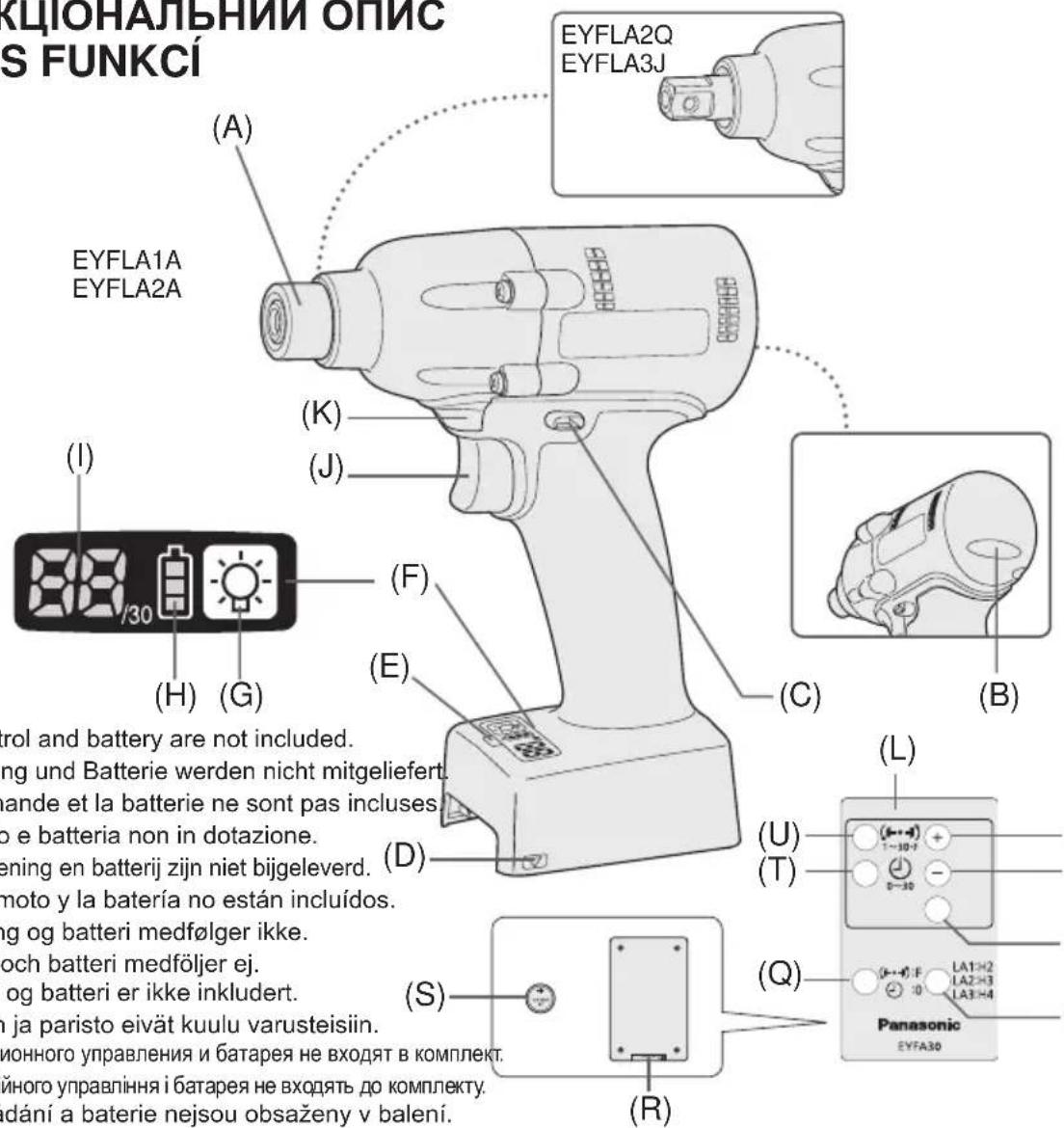
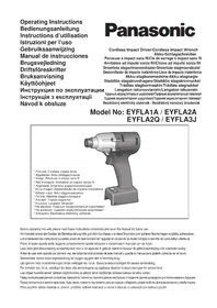
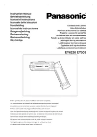
Remote control and battery are not included. Fernbedienung und Batterie werden nicht mit La telecommande et la batterie ne sont pas in Telecomando e batteria non in dotazione. Afstandsbediening en batterij zichniet bijgelevere El control remoto y la bateria no estan incluid Fjernbetjening og batteri medfolger icke. Fjarrkontroll och batteri medfoljer ej. Fjernkontroll og batteri er icke inkludert. Kaukosäadin ja paristo eivat kuulu varusteisi Nyblt dNCTaHIOHO ynpabIeHn i 6bTapeH He BXO Nyblt dNCTaHIOHO ynpabINHn i 6bTapeH Be XOJaTB Dalkove ovladani a baterie nejsou obsazeny
| (A) | 6.35 mm (1/4") hex quick connect chuck (EYFLA1A, EYFLA2A)/square drive (EYFLA2Q, EYFLA3J/Pin type)6,35 mm (1/4") Sechskant-Schnellaufspannffutter (EYFLA1A, EYFLA2A)/Vierkant (EYFLA2Q, EYFLA3J/Stifttyp)Mandrin de connexion rapide hexagonal de 6,35 mm (1/4")/entraînement carré (EYFLA2Q, EYFLA3J/Type à goujon)Mandrino esagonale di collegamento rapido da 6,35 mm (1/4")/attacco quadro (EYFLA2Q, EYFLA3J/Tipco con piolo)6,35 mm zeskantboorkop met snelkoppeling/vierkante aandrijing (EYFLA2Q, EYFLA3J/pen-type)Mandril hexagonal de conexión rápida de 6,35 mm (1/4")/Excitador cuadrado (EYFLA2Q, EYFLA3J/Tipco pasador)6,35 mm (1/4") hexagonal borepatron til hurtig tilsluting/firkantet drev (EYFLA2Q, EYFLA3J/stifttype)Snabbchuck med 6,35 mm sexkantshylsa/fyrkantskoppling (EYFLA2Q, EYFLA3J/stifttyp)6,35 mm (1/4") hexhurtigtlkoplingschuck/firkantdrev (EYFLA2Q, EYFLA3J/pinetype)6,35 mm (1/4") kuusiopiastukka/neliöavain (EYFLA2Q, EYFLA3J/nastatyyppi)6,35 MM (1/4") Μεστιραπήν Μηλρον Μβείτρο Μομοδεινηκη/Kβαρατήν Μχοστόνικ (EYFLA2Q, EYFLA3J/Πιθάνοτο Μητημα)6,35 MM (1/4") Μεστιραπήν Μηλρον Μβείτρο Μρηειδηκη/Kβαρατήν Μχοστόνικ (EYFLA2Q, EYFLA3J/Πιθάνοτο Μητημα)6,35 mm (1/4") Sveraci šroub s vηēsīm Šestihannym năslavcem (EYFLA1A, EYFLA2A)/vinitfičtýhran (EYFLA2Q, EYFLA3J/ tip s kontaktnim kolikem) | ||
| (B) | Tightening confirmation lampAnzugsbestätigungslampeTémoin de confirmation de serrageSpia confirma serraggioAanhaaltostand-bevestigingslampjeLámpara de confirmación de aprieteLampe til bekraeftse af stramningLampa für bekráftad átdragningStrammebekreftelesaslampeKirstyksen varmistuslamppuЛамоча постордения захкиЛамоча постордения захкиKontrolka utaženi | (C) | Forward/Reverse leverVorwärts-/RückwärtshebelLevier d' inversion marche avant/marche arrièreLeva di avanzamento/inversioneLinks/rechtsschakelaarPalanca de avance/marcha atrásGreb til forlaens/baglæns retiningRiktningsomkopplareForover-/bakoverbryterEteenpääin/taaksepäin vipuРычаг пereşклочения вреeding/HazadВaxijlb пereşmenkāнney вреeding/HazadSpinač prědiñho a zpétného chodu |
| (D) | Alignment markAusrichtmarkierungenMarques d'alignmentMarcature allineamentoUtitlijtekensMarcas de alineaciónFlugtemærkerAnpassningsmärkenOpprettingsmerkeSovitusmerkitMečni coobmeцениMični biviribuvaиьNzačka zarovnány | (E) | Remote control receiverFernbedienungsempfängerRécepteur de la télécommandeRicevitore telecomandoAfstandsbedieningontvangerReceptor de control remotoFjernbetjeningsmodtagerFjarrstymingsgivareFjernkontrollmottakerKaukosäätimen vastaanotinДатчник діstanciuonHoro упавелениДатчник діstanciuinHoro упавелениPřijímač signálu dálkového ovládání |
| (F) | Control panelBedienfeldPanneau de commandePannello di controlloBedieningspannelPanel de controKontrolpanelKontrollpanelKontrollpanelSàätöpaneeliПаень lyнравлиенияПаень lyнравлиionesKontrolni panel | (G) | LED light on/off buttonLED-Leuchten-EIN/AUS-TasteBouton Marche/Arrêt de la lumière DELTasti du accensione e spegnimento della luce LEDAan/uit-toets (ON/OFF) voor LED-lampjeBotón ON/OFF de luz LEDTAYEND/SLUK-knap til LED-lysStrömbrytrare für LED-ljusPA/AV-knapp for LED-lysLED-valon kytkin/katkaisupainikeКонingly вklуочения/вklуочения с被告ю indно indno podсову Кнокая Всимкеннивсимкенниьситладiodиоги рindсвуваняSpínač zap./vyp. elektroluminisencnfi diody LED |
| (H) | Battery indication lamp Akku-Anzeigelampe Témoin indicateur de la batterie Spia livello batteria Accu-indicatielampje Lámpara de indicatora de la batería Batteriindikatorlampe Batteriindikator Batteriindikasjonslampe Akin osoituslamppu Индигастория ламочьka батар Индигастория ламочьka баташи Kotrolka stavu baterie | (I) | Display Anzeige Affichage Display Display Visor Display Indikeringsfönster Display Näytö Ди检пел Ди检пел Displej |
| (J) | Variable speed control trigger Variabler Geschwindigkeitskontrollschalter Gächette de commande de vitesse Grilletto di controlo velocità variabile Startschakelaar met variabele torentalregeling Disparador del control de velocidad variable Kontroludløser for variabel hastighed Avtryckare med variabel varvitalsreglering Trinnløs hovedbryter Nopeudensäätökytkin Пerečnéчateль ретулировки петереньй сокорstп Ретемикay ретуливаньда мінношвдкостс Spouš' rychlostni regulace | (K) | LED light LED-Leuchte Lumière DEL Luce LED LED-lampje Luz indicatora LED-lys LED-lus LED-lys LED-valo С被告оюdnay посветка С被告оюdnay посветка Svetlo LED |
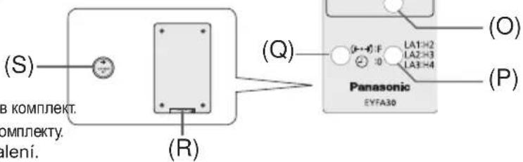
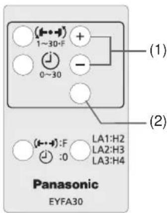
| (L) | Remote control Fernbedienung Télécommande Telekomando Afstandsbediening Control remoto Fjernbetjening Fjärnkontroll Fjernkontroll Kaukosäädin Пуньт дисционногу уразаленя Пуньт дисционногу уразаленя Dákové ovládání | (M) | + button Taste + Bouton + Taste + toets Botón + + knap Knapp (+) + knapp + painike Конка + Конka + Tlačitko + |
| (N) | - button Taste - Bouton - Taste - -toets Botón - -knap Knapp (-) -knap -painike Конka - Конka - Tlačitko - | (O) | OK button Taste OK Bouton OK Taste OK OK toets Botón OK (correcto) OK-knap Bekräftelseknapp OK knapp OK-painike Конka OK Конka OK Tlačitko OK |
| (P) | Torque level button Anzugsmomentstufentaste Bouton de niveau du couple de serrage Tasto livello coppia Aanhaalmoment-niveautoets Botón de palanca de par de torsión Knap til stramningsmomentniveau Väljare für momentnivá Dreiemomentknapp Vääntömomentin tasopainike Коньу уrobня крутыцero мочENTA Коньу рíвné крутольно мочentу Тlačitko regulace hladiny točíveho momentu | (Q) | Format button Formattaste Bouton de format Tasto formattingo Formatteertoets Botón de formato Formatknap Formateringsknapp Format knapp Formaatin painike Коньу Форматa Коньу Формату Rázové tlačitko |
| (R) | Holder Halter Support Supporto Houder Retenedor Holder Hällare Holder Pidin Держател Держak Držák | (S) | Battery Batterie Batterie Batteria Accu Batería Batteri Batteri Batteri Akku Батар Батар Baterie |
| (T) | Interval set button Intervall-Einstelltaste Bouton de réglage de l'intervalle Tasto impostazione intervallo Interval-insteltoets Botón de ajuste de intervalo Intervalindstellingsknap Intervallinställningsknapp Intervallinnstellingsknapp Jakson säätöpainike Коньу установки Interteba Коньу встановке Interteba Тlačitko intervolného nastavení | (U) | Torque set button Anzugsmoment-Einstelltaste Bouton de réglage du couple de serrage Tasto impostazione coppiα Aanhaalmoment-insteltoets Botón de ajuste de par de torsión Knap til indstilling af stramningsmoment Momentinställningsknapp Dreiemomentinnstellingsknapp Vääntömomentin säätöpainike Коньу установки Крутуцero мочENTA Коньу встановке Крутольно мочentу Тlačitko nastavení hladiny točíveho momentu |
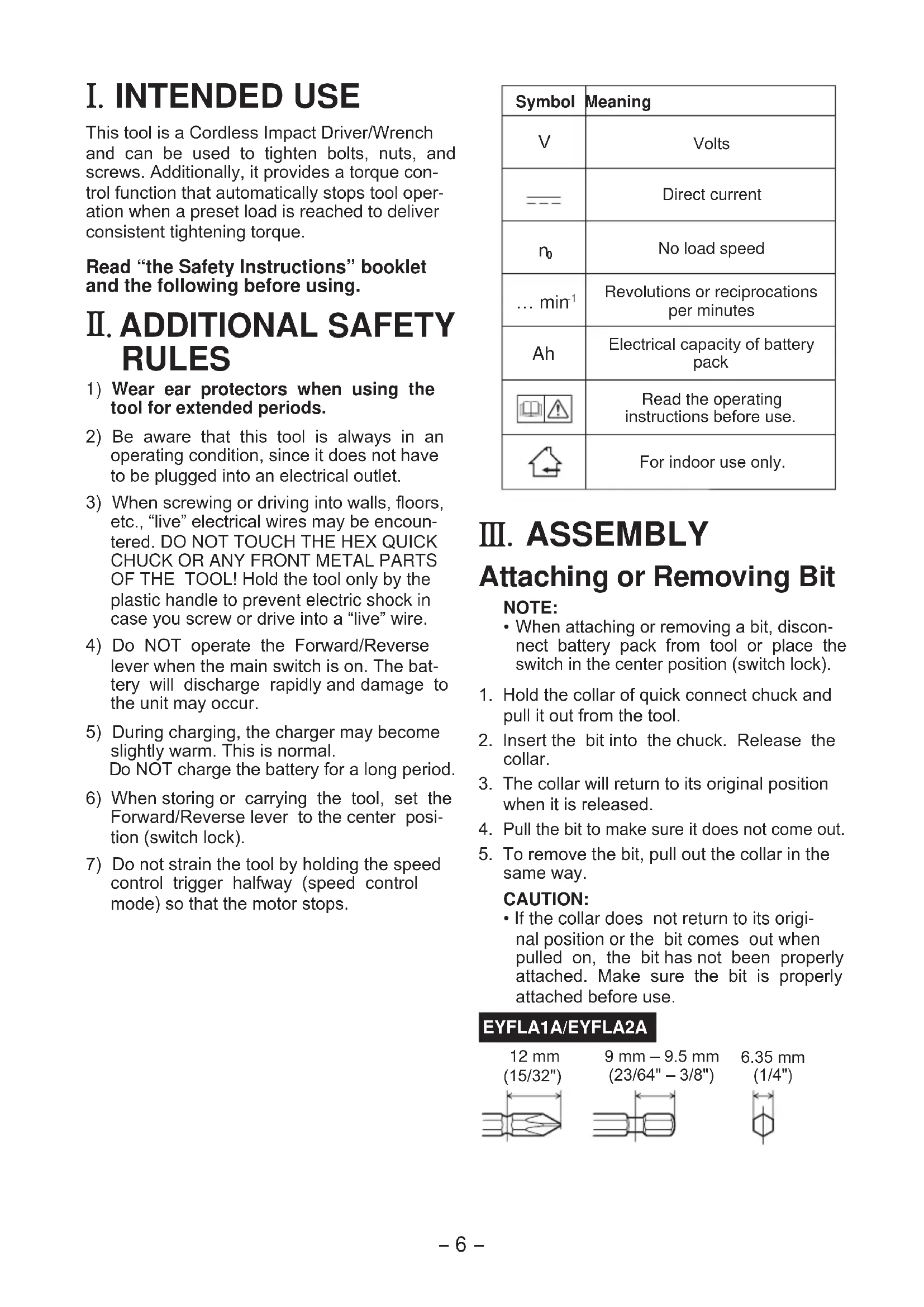
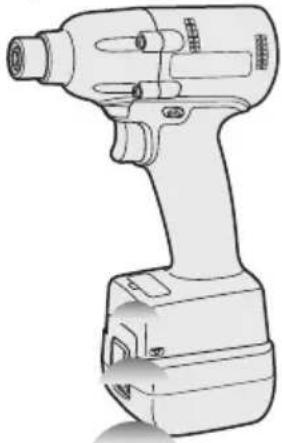
I. INTENDED USE
This tool is a Cordless Impact Driver/Wrench and can be used to tighten bolts, nuts, and screws. Additionally, it provides a torque control function that automatically stops tool operation when a preset load is reached to deliver consistent tightening torque.
Read "the Safety Instructions" booklet and the following before using.
II. ADDITIONAL SAFETY RULES
1) Wear ear protectors when using the tool for extended periods.
2) Be aware that this tool is always in an operating condition, since it does not have to be plugged into an electrical outlet.
3) When screwing or driving into walls, floors, etc., "live" electrical wires may be encountered. DO NOT TOUCH THE HEX QUICK CHUCK OR ANY FRONT METAL PARTS OF THE TOOL! Hold the tool only by the plastic handle to prevent electric shock in case you screw or drive into a "live" wire.
4) Do NOT operate the Forward/Reverse lever when the main switch is on. The battery will discharge rapidly and damage to the unit may occur.
5) During charging, the charger may become slightly warm. This is normal. Do NOT charge the battery for a long period.
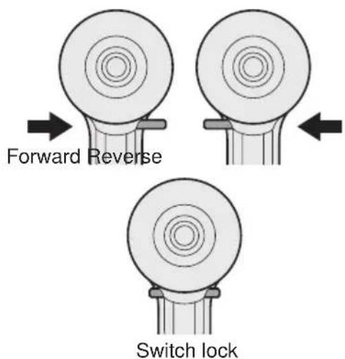
6) When storing or carrying the tool, set the Forward/Reverse lever to the center position (switch lock).
7) Do not strain the tool by holding the speed control trigger halfway (speed control mode) so that the motor stops.
| Symbol | Meaning |
| V | Volts |
| — | Direct current |
| n₀ | No load speed |
| ... min⁻¹ | Revolutions or reciprocations per minutes |
| Ah | Electrical capacity of battery pack |
| Read the operating instructions before use. | |
| For indoor use only. |
III. ASSEMBLY
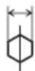
Attaching or Removing Bit
NOTE:
-
When attaching or removing a bit, disconnect battery pack from tool or place the switch in the center position (switch lock).
-
Hold the collar of quick connect chuck and pull it out from the tool.
- Insert the bit into the chuck. Release the collar.
- The collar will return to its original position when it is released.
- Pull the bit to make sure it does not come out.
- To remove the bit, pull out the collar in the same way.
CAUTION:
- If the collar does not return to its original position or the bit comes out when pulled on, the bit has not been properly attached. Make sure the bit is properly attached before use.
EYFLA1A/EYFLA2A
12 mm (15/32")
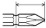
9 mm - 9.5 mm (23/64" - 3/8")
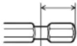
6.35 mm (1/4")
Attaching Socket
- Remove the socket's rubber ring and pin.
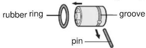
① Attach the socket to the tool.
② Insert the pin. (Taking care to align the pin holes on the socket and tool.)
③ Attach the rubber ring by sliding it into place over the groove.
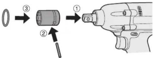
NOTE:
Be sure to attach the rubber ring to prevent the pin from falling out.
Removing Socket
① Remove the rubber ring.
② Remove the pin.
③ Remove the socket from the tool.
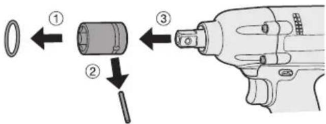
NOTE:
Keep the temperature of the tool above the freezing point (0^ / 32^) when attaching sockets to or detaching them from the square drive on the tool. Do not use excessive force when attaching or detaching sockets.
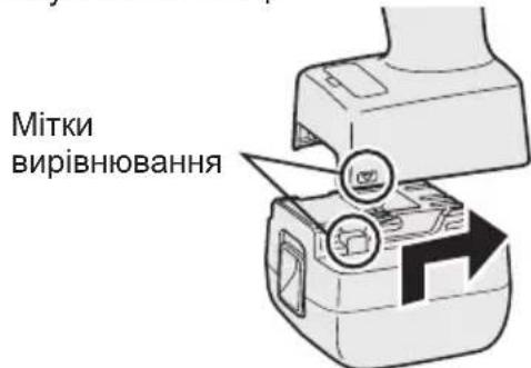
Attaching or Removing Battery Pack
-
To connect the battery pack: Line up the alignment marks and attach the battery pack.
-
Slide the battery pack until it locks into position.
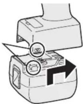
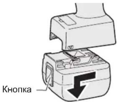
Alignment marks
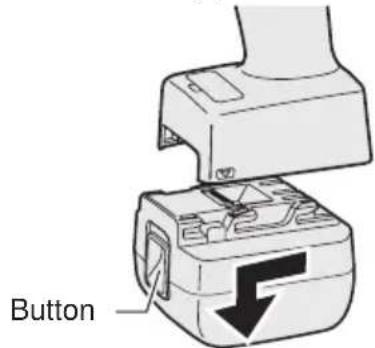
- To remove the battery pack: Push up on the button from the front to release the battery pack.
IV. OPERATION
Before Using the Remote Control (Available as an optional accessory)
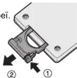
Insert the battery
- Pull out the battery holder.
① Push in on the fastener as indicated by the arrow.
② Pull out the holder.
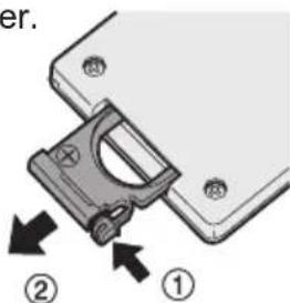
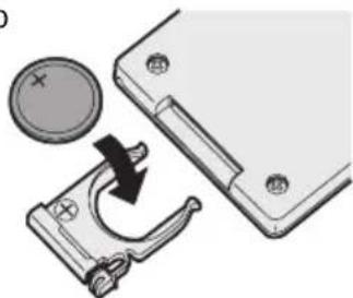
- Insert the battery and push the holder back in.
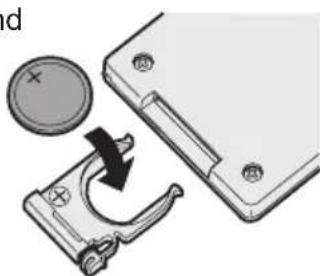
NOTE:
- If the tool does not respond to the wireless remote control even when the remote control is operated close to the tool, the battery (CR2025) is dead. Replace it with a fresh battery.
- The included battery is provided for sample use and may not last as long as commercially available batteries.
Wireless remote control range
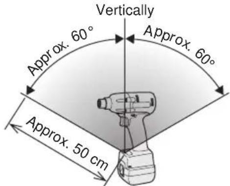
The remote control should be operated within approximately 50~cm and approximately 60^ vertically and horizontally of the perpendicular relative to the infrared receiver on the tool.
-
Under the following circumstances, you may not be able to operate the tool, even within this range.
-
If there is an object between the remote control's transmitter and the tool's receiver.
-
Use outdoors or in other environments where the remote control receiver is exposed to a strong light source, or when the remote control transmitter or receiver is dirty may cause the tool to fail to respond, even when the remote control is used within the operating range.
[Main Body]
Switch and Forward/Reverse Lever Operation
CAUTION:
To prevent damage, do not operate Forward/Reverse lever until the bit comes to a complete stop.
Forward Rotation Switch Operation
- Push the lever for forward rotation.
- Depress the trigger switch slightly to start the tool slowly.
- The speed increases with the amount of depression of the trigger for efficient tightening of screws. The brake operates and the bit stops immediately when the trigger is released.
- After use, set the lever to its center position (switch lock).
Reverse Rotation Switch Operation
- Push the lever for reverse rotation. Check the direction of rotation before use.
- Depress the trigger switch slightly to start the tool slowly.
- After use, set the lever to its center position (switch lock).
CAUTION:
- To eliminate excessive temperature increase of the tool surface, do not operate the tool continuously using two or more battery packs. Tool needs cool off time before switching to another pack.
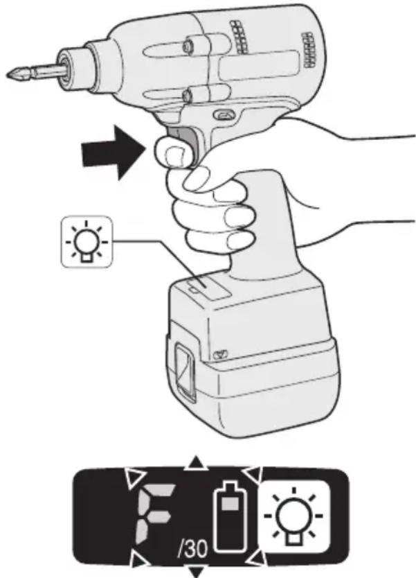
Tightening confirmation lamp
- The tightening confirmation lamp can be used to check whether the torque control function was activated.
| Tool status Lamp display | |
| Tightening complete (with torque control function operation) | Green (For approx. 2 seconds) |
| ·Tightening not complete ·Tightening complete with retightening within 1 second | Red (For approx. 2 seconds) |
| The automatic stop function has been activated. | Red (For approx. 5 minutes) |
CAUTION:
- When the tool stops automatically after the switch is released during impact-mode tightening and then reengaged within 1 second, the red lamp will light up to indicate the risk of excessive torque application as a result of retightening.
NOTE
- The tightening confirmation lamp will not turn on under the following conditions:
- When the torque clutch is set to "F"
- During reverse rotation operation
- The lamp turns off when the tool is in operation.
Control Panel
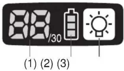
(1) LED light
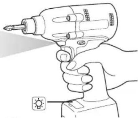
Pressing the button toggles the LED light on and off.
The light illuminates with very low current, and it does not adversely affect the performance of the tool during use or its battery capacity.
CAUTION:
- The built-in LED light is designed to illuminate the small work area temporarily.
- Do not use it as a substitute for a regular flashlight, since it does not have enough brightness.
Caution: DO NOT STARE INTO BEAM.
Use of controls or adjustments or performance of procedures other than those specified herein may result in hazardous radiation exposure.
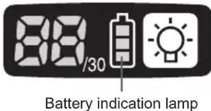
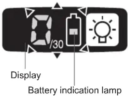
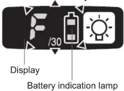
(2) The battery indication lamp
- Use the battery indication lamp to check how much power is left in the battery.
- Battery life varies slightly with ambient temperature and battery characteristics. The lamp is designed to provide a rough indication of remaining battery life.

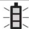
Battery indication lamp
| Indicator Battery status | |
| Fully charged | |
| Approx. 40% or less remaining | |
| Flashing Approx. 20% or less remaining (indicates need to recharge battery) The battery pack will need to be charged soon. | |
| No charge The battery pack needs to be charged. (The tool's automatic power-off function will activate at this stage.) | |
Automatic power-off function
- The automatic power-off function is designed to prevent a loss of tightening torque due to reduced battery voltage. Once it has been activated, the tool will not operate until the battery pack has been charged (or replaced with a fresh unit), even if the trigger is depressed.
Indicator
Flashing
NOTE:
- All 3 bars on the battery indication lamp will flash when the automatic power-off function is activated.
- When the battery indication lamp begins flashing, the battery pack should be charged (or replaced with a fresh unit) immediately.
- Be sure to fully charge the battery pack in question after activation of the automatic power-off function. Failure to do so may prevent the automatic power-off function from being properly deactivated.
(3) The torque control function
- The torque control function calculates the load from the motor's rotational angle during the hammer impact and determines that the bolt has been properly seated when a preset load value is exceeded. Driving is then automatically stopped after a preset number of impacts have been delivered to the bolt.
CAUTION:
- Always check the tool's tightening torque before use. Improper tool operation may result in excessive or inadequate tightening.
CAUTION:
- Always operate the tool with the switch fully engaged. The torque control function will not operate when the switch is not sufficiently engaged, preventing the tool from stopping automatically.
- In work where a heavy load comes to bear during tightening, the load may be interpreted as the seating of the bolt, preventing the bolt from being completely tightened.
- Repeated tightening of the same bolt may break the bolt or deform the material into which the bolt is being driven as a result of excessive tightening.
- The tightening torque value and precision vary with factors such as the material into which the bolt is being driven and the condition of the socket being used. Adjust the torque as necessary for the work being performed. Bolt tightening torque varies due to the factors described below.
1) Bolt
- Bolt diameter: Tightening torque generally increases with bolt diameter.
- Torque coefficient (indicated by the bolt manufacturer), grade, length, etc.
2) Other
- Bit and socket condition: Material, amount of play, etc.
- Use of a universal joint or socket adapter
- User: Manner in which the tool is applied to the bolt, strength with which the tool is held, manner in which the tool's switch is engaged
- Condition of object being tightened: Material, seating surface finish
Setting the tool to configuration mode
- Turn off the control panel.
- If the control panel is on, remove and then reinsert the battery pack.
- Engage the switch while pushing the button and then release both the button and the switch.
After all the LED lamps have turned off, the control panel will flash and change to configuration mode.
NOTE:
- Tools ship from the factory set to "F" mode (torque control function off).
- The control panel will turn off if the tool is not operated for a period of 5 minutes.
Configuring the torque clutch setting
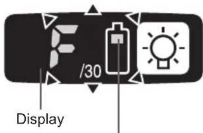
Battery indication lamp
- Press the and buttons to select the clutch setting that is appropriate for the work being performed.
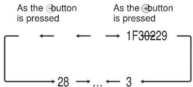
-F indicates that the torque control function is off.
- You can select from 30 torque clutch settings (1 to 30).
-
Use figures from the Tightening Torque Chart to guide your selection of torque clutch setting. (See the following tightening torque chart)
-
Press the OK button to accept the selected torque clutch setting.
-
The control panel will stop flashing and light up.
CAUTION:
- You must press the OK button in order for the selected setting to take effect.
- Be sure to verify the new value after changing the setting. (See page 12.)
Tightening Torque Chart (for Reference Use)
The values illustrated on this chart were measured under the conditions described below and are provided for reference purposes. Actual tightening torque varies with ambient conditions (the particular bolt being tightened, hardware being used, method of holding the bolt in place, etc.).
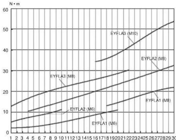
Measurement conditions
Temperature: Room temperature (20^ / 68^)
Using the Interval Set
-
The interval set operates to prevent the tool from operating after it automatically stops as a result of the torque control function, even if the switch is engaged.
-
Set the tool to configuration mode. (See page 10.)
-
Press the interval set button.
-
The control panel will begin flashing. Display: The number 0 flashes on and off. Battery indication lamp: The middle bar of the battery flashes on and off.
- Press the and buttons to set the desired time.
| Buttons Display Seconds | ||
| + - | 30 | 3 |
| : | : | |
| 1 0.1 | ||
| 0 Off | ||
-
Press the OK button to accept the selected setting.
-
The control panel will stop flashing and light up, and the torque clutch setting will be displayed.
CAUTION:
- Be sure to verify the new value after changing the setting.
Initializing All Settings
Factory settings
- Torque clutch setting: "F" (torque control function off)
-
Interval setting: 0 (off)
-
This section explains how to revert all tool settings to their default values at the time of shipment from the factory.
-
The error display will be turned off.
-
Set the tool to configuration mode. (See page 10.)
-
Press the format button.
-
The control panel will begin flashing. Display: The letter "F" flashes on and off. Battery indication lamp: The upper and lower bars of the battery flash on and off.
-
Press the OK button to accept the selected setting.
-
The control panel will stop flashing and light up.
Checking Tool Settings
- This section describes how to have the tool display current settings for approximately 3 seconds when the tool is stopped.
- You cannot check tool settings when the control panel is turned off. First, engage the switch briefly to reactivate the display.
Checking the torque clutch setting
-
Press the torque set button.
-
Control panel display Display: The torque set lights up.
Battery indication lamp: The upper bar of the battery flashes on and off.
Checking the interval
- Press the interval set button.
Control panel display Display: The interval set lights up.
Battery indication lamp: The middle bar of the battery flashes on and off.
Checking tool circuits
-
Press the torque set button.
-
Control panel display Display: The torque set display lights up. Battery indication lamp: The middle and lower bars of the battery flash on and off.
| Display Tool circuit | |
| H2 | EYFLA1 |
| H3 | EYFLA2 |
| H4 | EYFLA3 |
NOTE:
- If you engage the switch while a setting is being displayed, the control panel will revert to the torque clutch setting display.
CAUTION:
The torque set display is not intended to be used to identify the type of drive component parts (hammer, etc.) used in a particular tool.
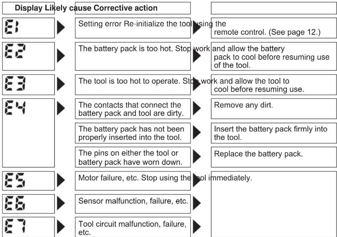
Error Display
In the event of a tool or battery pack malfunction, the control panel will display an error message. Please check the tool or battery pack as described in the following chart before having them serviced.
[Battery Pack]
For Appropriate Use of Battery Pack
Li-ion Battery Pack (EYFB30)
- For optimum battery life, store the Li-ion battery pack following use without charging it.
- When charging the battery pack, confirm that the terminals on the battery charger are free of foreign substances such as dust and water etc. Clean the terminals before charging the battery pack if any foreign substances are found on the terminals.
The life of the battery pack terminals may be affected by foreign substances such as dust and water etc. during operation.
- When battery pack is not in use, keep it away from other metal objects like: paper clips, coins, keys, nails, screws, or other small metal objects that can make a connection from one terminal to another.
Shorting the battery terminals together may cause sparks, burns or a fire. - When operating the battery pack, make sure the work place is well ventilated.
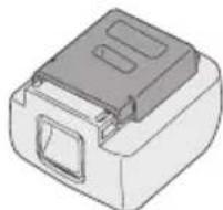
- When the battery pack is removed from the main body of the tool, replace the battery pack cover immediately in order to prevent dust or dirt from contaminating the battery terminals and causing a short circuit.
Battery Pack Life
The rechargeable batteries have a limited life. If the operation time becomes extremely short after recharging, replace the battery pack with a new one.
Battery Recycling
ATTENTION:
For environmental protection and recycling of materials, be sure that it is disposed of at an officially assigned location, if there is one in your country.
[Battery Charger]
Charging
Read the operating manual for Panasonic battery charger for the battery pack before charging.
Before charging the battery
When charging EYFB30:
Charge the battery at a temperature of 5^ (41^) to 40^ (104^) .
The battery pack cannot be charged at a temperature of less than 5^ (41^) . If the temperature of the battery pack is less than 5^ (41^) , first remove the battery pack from the charger and allow it to sit for an hour in a location where the temperature is 5^ (41^) or warmer. Then charge the battery pack again.
Information for Users on Collection and Disposal of Old Equipment and used Batteries


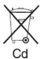
Cd
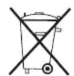
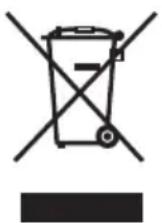
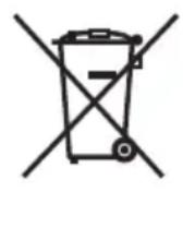
These symbols on the products, packaging, and/or accompanying documents mean that used electrical and electronic products and batteries should not be mixed with general household waste.
For proper treatment, recovery and recycling of old products and used batteries, please take them to applicable collection points, in accordance with your national legislation and the Directives 2002/96/EC and 2006/66/EC.
By disposing of these products and batteries correctly, you will help to save valuable resources and prevent any potential negative effects on human health and the environment which could otherwise arise from inappropriate waste handling.
For more information about collection and recycling of old products and batteries, please contact your local municipality, your waste disposal service or the point of sale where you purchased the items.
Penalties may be applicable for incorrect disposal of this waste, in accordance with national legislation.
For business users in the European Union
If you wish to discard electrical and electronic equipment, please contact your dealer or supplier for further information.
[Information on Disposal in other Countries outside the European Union]
These symbols are only valid in the European Union. If you wish to discard these items, please contact your local authorities or dealer and ask for the correct method of disposal.
Note for the battery symbol (bottom two symbol examples):
This symbol might be used in combination with a chemical symbol. In this case it complies with the requirement set by the Directive for the chemical involved.
V. MAINTENANCE
Use only a dry, soft cloth for wiping the unit. Do not use a damp cloth, thinner, benzine, or other volatile solvents for cleaning.
VI. ACCESSORIES
Charger
- EY0L80
Battery pack
EYFB30
Remote control
- EYFA30
Protector for tool
-
EYFA01-A (Blue)
-
EYFA01-Y (Yellow)
-
EYFA01-H (Gray)
Protector for battery
- EYFA02-H
VII. SPECIFICATIONS
MAIN UNIT
| Model EYFLA1 EYFLA2 EYFLA3 | |||||
| A A Q J | |||||
| Moter 10.8 V DC | |||||
| Chuck size | Single-ended | 9 - 9.5 mm(23/64" - 3/8") | 9 - 9.5 mm(23/64" - 3/8") | ☐9.5 mm(3/8") | ☐12.7 mm (1/2") |
| Double-ended | 12 mm (15/32") | 12 mm(15/32") | |||
| No load speed | Stage | 1 0 - 950 | 1 0 - 1300 | 0 - 2300 | |
| 2 0 - 1000 | 2 0 - 1450 | ||||
| 3 - 5 0 - 1050 | 3 0 - 1550 | ||||
| 6 0 - 1300 | 4 - 30-F | 0 - 2300 | |||
| 7 0 - 1450 | |||||
| 8 0 - 1550 | |||||
| 9 - 30-F 0 - 2300 | |||||
| Impact per minute | Stage | 1 0 - 1900 | 1 0 - 2500 | 0 - 3000 | |
| 2 0 - 1950 | 2 0 - 2800 | ||||
| 3 - 5 0 - 2100 | 3 0 - 3000 | ||||
| 6 0 - 2500 | 4 - 30-F | 0 - 3600 | |||
| 7 0 - 2800 | |||||
| 8 0 - 3000 | |||||
| 9 - 30-F 0 - 4000 | |||||
| Maximum torque | 40 N·m(408 kgf-cm, 354 in-lbs) | 90 N·m(918 kgf-cm, 796 in-lbs) | 120 N·m (1224 kgf-cm, 1062 in-lbs) | ||
| Torque control function operating range | Approx. 3 - 22 N·m(31 - 224 kgf-cm, 27 - 195 in-lbs) | Approx. 6 - 30 N·m(61 - 306 kgf-cm, 53 - 266 in-lbs) | Approx. 16 - 53 N·m(163 - 540 kgf-cm, 142 - 469 in-lbs) | ||
| Overall length | 158 mm (6-7/32") | 164 mm (6-7/16") | |||
| Weight (with battery pack: EYFB30) | 1.3 kg (2.8 lbs) | 1.35 kg (2.9 lbs) | |||
BATTERY PACK (not included with shipment)
| Model EYFB30 | |
| Storage battery Li-ion battery | |
| Battery voltage 10.8 V DC (3.6 | V/6 cells) |
| Capacity 3 Ah |
BATTERY CHARGER (not included with shipment)
| Model EY0L80 | |
| Rating See the rating plate on the bottom of the charger. | |
| Weight 0.95 kg (2.1 lbs) | |
[Li-ion battery pack]
| Charging time | 3 Ah | 10.8 V |
| EYFB30 | ||
| Usable: 40 min. | ||
| Full: 65 min. |
Remote control (not included with shipment)
| Model EYFA30 | |
| Battery voltage 3 V DC | |
| Dimensions 54 mm (2-1/8") × 86 mm (3-3/8") × 10 mm (13/32") | |
| Weight (with battery) Approximately 29 g (0.6 lbs) | |
ONLY FOR U. K.
VIII. ELECTRICAL PLUG INFORMATION
FOR YOUR SAFETY PLEASE READ THE FOLLOWING TEXT CAREFULLY
This appliance is supplied with a moulded three pin mains plug for your safety and convenience.
A 5 amp fuse is fitted in this plug.
Should the fuse need to be replaced please ensure that the replacement fuse has a rating of 5 amp and that it is approved by ASTA or BSI to BS1362.
Check for the ASTA mark or the BSI mark on the body of the fuse.
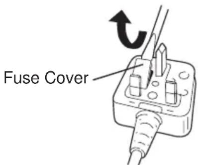
If the plug contains a removable fuse cover you must ensure that it is refitted when the fuse is replaced.
If you lose the fuse cover the plug must not be used until a replacement cover is obtained.
A replacement fuse cover can be purchased from your local Panasonic Dealer.
IF THE FITTED MOULDED PLUG IS UNSUITABLE FOR THE SOCKET OUTLET IN YOUR HOME THEN THE FUSE SHOULD BE REMOVED AND THE PLUG CUT OFF AND DISPOSED OF SAFELY.
THERE IS A DANGER OF SEVERE ELECTRICAL SHOCK IF THE CUT OFF PLUG IS INSERTED INTO ANY 13 AMP SOCKET.
If a new plug is to be fitted please observe the wiring code as shown below.
If in any doubt please consult a qualified electrician.
IMPORTANT:
The wires in this mains lead are coloured in accordance with the following code:
Blue: Neutral
Brown: Live
As the colours of the wire in the mains lead of this appliance may not correspond with the coloured markings identifying the terminals in your plug, proceed as follows.
The wire which is coloured BLUE must be connected to the terminal in the plug which is marked with the letter N or coloured BLACK.
The wire which is coloured BROWN must be connected to the terminal in the plug which is marked with the letter L or coloured RED.
Under no circumstances should either of these wires be connected to the earth terminal of the three pin plug, marked with the letter E or the Earth Symbol 1一
How to replace the fuse: Open the fuse compartment with a screwdriver and replace the fuse and fuse cover if it is removable.
This apparatus was produced to BS800.
| Display Circuito attrezzo | |
| H2 EYFLA1 | |
| H3 EYFLA | 2 |
| H4 EYFLA3 | |
NOTA:
Pacco battery Li-ion (EYFB30)
ДяпpeDoTbpaueHЯ NOBpeKdEHHa He NcNoIb3yIe pblur nepeKJIoueHHa BpePeJ/Ha3aI Do Tex nop, NOKa HacaJaKa NOJIHOCTbIO He OCTaHOBITcR.
PpOBepka yctaHOBKn 6JNOKINPOBOUHOn MyTbI
- Haxmnte KhoNky yCTaHOBKn kpyTaeo MOMeHTa
Cpok cnyk6bI 6aTapeHoro 6noka
AkkymyIaTOPbIe 6aTapeu IMeIOT orpaHnueHHbI cPcK cnyX6bl. Ecnn nocne 3apJKn Bpemr cyHKUHOHPOBaHnra CtaHOBITcR Ype3MepHo KOpOTKm, 3aMeHnTe 6aTapeHbI 6bOK Ha HOBbI.
YtJn3aun6aTapeu BHIMAHNE:
B ueJx 3aunTbI OkpykaIOUeN cpebl I yTuIN3aUIN MaTePnAIOB, yBeINTEcb, UTO OHa yTuIN3InPOBaHbOOnuJIbHO npEJa3HaueHHOM MeCTe, eCNI TaKOBbieEcTB B BaSei CTpaHe.
[3apяДhoe yctpoIcTBΦ 3apяДka
IpepeBbINOHeHnem 3apAKn npOHTe pyKOBOCTBO no 3KcNpyatauun K 3apAHDomy yctpoiCTby Panasonic dna 6bataepHoro 6loka.
Ipeed 3apdkoB 6aTapeN
При Вылнонени 3ардкбатар end EYFB30: 3apякай Te 6atapeo npn Tempepatype ot 5^ (41^) do 40^ (104^)
3apraKa 6aTapeHoro 6noka npi Tempeatype Hnke 5^ (41^) HeBO3MOxHa. Ecnn Tempepatya 6aTapeHoro 6noka Hnke 5^ (41^) ,chauana n3BNEKHTe 6aTapeHbI 6nOK n3 3apAHO rCTpOInCTBa I daTe eMy HarpeTbcra B TeueHne yaca B MeCTe, rDe Tempepatya Doctnraet 5^ (41^) INN Bblwe. 3aTeM CHOba 3apAInTe 6aTapeHbI 6nok.
HnopmaunnoobpaueHHIO COTXODAMN DnA CTpaH, He BXOJxNxB Ebponeckn Co03
IeNCTBnE 3Tnx CnMBOJIOB paCnpocTpahReTc TOnbko Ha Ebponeeckn Co103.
Ecnn Bbl co6npaTeCb Bbl6pocntb daHHbIe 3neMeHTbl, y3HaTte B MeCThBIX opraHax Bnactn nn y dInlepa, KaK CNeJyET NOcTyNaTb C OTXoamn TAKOTO Tnna.
V. OBCJnyKINBAHNE
VII.TEXHINUeCKNE XAPAKTEPNUCTNKIOCHOBHOE YCTPOIcTBO
3MiCITb 6atapeHn 6NOK, DOKN BIn He 3a
2.ДЯЗIMAHNA6batapeHoro6IOKy: HATNCITbHa KhoNky cnepeDy IJIa BnBInbHeHHa 6batapeHoro6IOKy.
IV.Фуннционываяня
Ipeed BnKOpncTaHHaM NylbTy DnCTaHciiHoro ynpablniHHa (DocT yN H O rO B JaKOcTi doataKOBOr npnaad)
BcTaBTe 6aTapeio
- BntaHrHiB IepXak 6aTaapei.
① HataNCHiB Ha 3aunKy B HanpMky, kIn Bka3aHO cTpiKoIO.
② BntaHItb depXka.
- BCTaHOBITb 6aTapeIO i BCTaBTe DepKak Ha3aI.
PIMITKA
IHKUO IHCTpymeHT He pearye Ha II 3 NylbTom DnCTaHcuiHOro ynpabInHHa HabITb KUO BIn 3HaxODntBCa nopA3 IHCTpymeHTOM,Ce O3Hauea, Uo 6aTape (CR2025) po3prJxHeHa. 3amHtB II HOBIO 6atapeciio.
BaTape, lo BxOuNTb do KOMnJIeKTy, npn3NaYeHa dIa DEMOHCTpauiHoro BnKOpNCtAHn i MoKe npOnpaIOBAtn He TaK DoBro, k BaTapei, lo npncyTHi B npoDaKy.
Po6oyn diana30n 6e3dpoTOBOrO nyIbTa DnCTaHcuiHoro ynpabNInHna
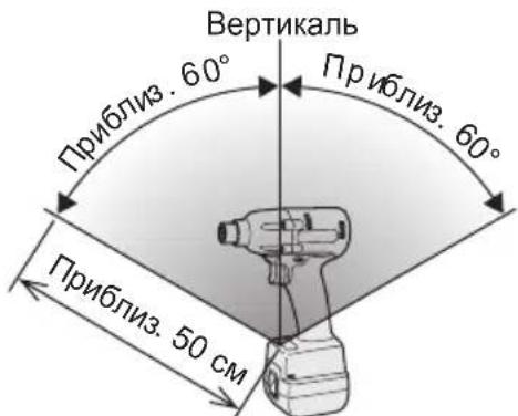
Onepaui 3 npbTom dntaHnHoro npabInnHeo6xio HO BnKohyBaTN Ha BiDCTaHI He 6Ibwe50cm IB Mekax KyTa 60^ BiHocHO BeptnKaJI nepenEniKyIpyHO do iHpaepBOHO daTnKa IHcTpymenta
Habitb B Mexax Bka3aHoro diana3OHy po6ota 3 IHCTpyMeHTOM MOKe 6yTu HEMOXJINBOIO 3a HAcTyNHx yMOB
- Y BUNaIky HArBHOCTI NpeMeta MIX nepeDaTcHKOM NylbTa DnCTaHcIHORO ynpabLIHHI DaTcHKOM IHCTpyMeHTa.
-Плд уас ВИКОпСТаHHЯ Ha3OBHи npIMiUeHHa60В iHux yMOBax, KONД DAtчNKДИCTaHcIINHOуnpaBnIHн 3HaxOДNTbCЯ ПДВЛNBOM CINbHOrO JxKepeNa CBITna, a60ЯKsoNepeDAtчNKpyNbTa DnCTaHcIINHOуnpaBnIHnA60 DaTчNK 3a6pydHeNo, lo MoKe pN3BecTudo BIDCyTHocTi peakuiI INCTpymEHTy HabITbB TOMY BInaDky, KONI ONEpaQii 3 NylbTomДИCTaHcIINHOуnpaBnIHн BИKOHyIOTbcRBMexkaxpo6OOro diana3OHy.
IiDCBiyBaHHrROPITb npn DyKe Hn3bKOMy Ctpymi He BnInBaE HeratNBHO Ha npOdyKTNBHicTB iHCTpyMeHTy NiJ yac po6OTn a6o Ha emKiCTb NOro 6aTapei.
YBARA
B6ydoBaHe CbitIOJIOHe NiDCBiyBaHH npn3HaueHe IJI TmUacOBOrO OCBiTJeHHa HeBeNIKOJ pOboOoi 3OHN.
He BnKOpNCToBvTe NOrO y KocTi 3aMInNoCTiHOro JixTapNka, TAK YK BOHO He MaeDOCTaTHBoI RCKpaBOCTi.
Ybara:HEINBNTUCHAHPOMIHB.
MOKOpNCTaHHoopraHbYnpabnIHnA6OperyIHOBaHb,
BO BnKOHaHHnPoUeDpy IHsIM YHOM, HIX
a3aHO BdaHIn HCtpyKci,MOKe PpN3BcTNI
IOPTpanJIHHnPiD BnINB He6e3neuHOr
INPOMiHOBaHH.
- CkopnctaTecb KHONKAMN Ta DnBCTaHOBJIeHHa NOTpi6HOrO yacy.
- Hatachitb KhoNky BCTaHOBJIeHHKpyTINbHOro MOMeHTy.
[3apdHn npncptpi] 3apdka
IpepeBnKoHaHHa3apAKn npOHTaTe noci6HnK 3 ekCnnyataciD zo 3apAHorO npucTpo Panasonic dna 6atapeHoro 6noKy.
Peped 3apdko6aTapei
Y BnnaKy BnkoHaHn 3apdKn 6aTaapei EYFB30: 3apJxJaTe 6aTapeo npn Tempeatypi BiD 5^ (41^) do 40^ (104^)
3apraKa 6atapeHoro 6nOky npi TempepaTypi HxKye 5^ (41^) hemoxJnBa. KaIO TempepaTypa 6atapeHoro 6nOky HxKye 5^ (41^) cnooyaTky BntarHtB 6atapeHnN 6nok i3 apyHoro npucTroo i daIte NOMy Harpitncn npotrrom yacy B Micci, de Tempepatya crae 5^ (41^) a6o Bnue. Notim 3HOBy 3apadItb 6atapeHnN 6nok.
Ihopmaia yo do yTnlaaii B kpaHax, kHe BXOJbB CBponecckn Co03


ДаHI CnMBOJN DiIcHi TINbKN Ha TepuTOpII CBpOeNcBkoro CoI3y.
Pn noTppe6i yTnI3aui DaHnx enemehtib 3BepHiTbcra Do MicueBoro KepiBnucTba abo dInepa uOdo npabunbHoro MeToy ii 3diincheHHra.
V. OBCJnyROBYAHHЯ
Дя npotnapaHH npucptpo BnKOpncTOByTe cyxy M'ky TkaHHy. He BnKOpncTOByTe dny OunueHH BOJORY TkaHHy, po3piJxvBauchen a6o iHwi Jetyi po3uHHNKn.
VI.IPNIJAIDJI
3apnnpictpi
- EY0L80
BaTapeHn6Jok
- EYFB30
IyblT dNCTaHciHoro ynpabNIIHHA
- EYFA30
3axnHn npncptpi dny iHctpymEnty
-
EYFA01-A (Cunhi)
-
EYFA01-Y (KoBtun)
-
EYFA01-H (Cipni)
3axnH npicpii Jla 6aapei
- EYFA02-H
VII.TEXHIUHIXAPAKTEPNCNUOCHOBHNIPINCTPII
EY9710FLA11 H2009 Printed in Japan

- INTENDED USE
- ADDITIONAL SAFETY RULES
- ASSEMBLY
- Attaching or Removing Bit
- NOTE:
- CAUTION:
- EYFLA1A/EYFLA2A
- Attaching Socket
- Removing Socket
- Attaching or Removing Battery Pack
- OPERATION
- Before Using the Remote Control (Available as an optional accessory)
- Insert the battery
- Wireless remote control range
- [Main Body]
- Switch and Forward/Reverse Lever Operation
- Forward Rotation Switch Operation
- Reverse Rotation Switch Operation
- Tightening confirmation lamp
- NOTE
- Control Panel
- LED light
- The battery indication lamp
- Automatic power-off function
- The torque control function
- 2) Other
- Setting the tool to configuration mode
- Configuring the torque clutch setting
- Tightening Torque Chart (for Reference Use)
- Using the Interval Set
- Initializing All Settings
- Factory settings
- Checking Tool Settings
- Error Display
- [Battery Pack]
- For Appropriate Use of Battery Pack
- Li-ion Battery Pack (EYFB30)
- Battery Pack Life
- Battery Recycling
- ATTENTION:
- [Battery Charger]
- Charging
- Before charging the battery
- Information for Users on Collection and Disposal of Old Equipment and used Batteries
- For business users in the European Union
- [Information on Disposal in other Countries outside the European Union]
- Note for the battery symbol (bottom two symbol examples):
- MAINTENANCE
- ACCESSORIES
- SPECIFICATIONS
- ONLY FOR U. K.
- ELECTRICAL PLUG INFORMATION
- FOR YOUR SAFETY PLEASE READ THE FOLLOWING TEXT CAREFULLY
- IMPORTANT:
- NOTA:
- Pacco battery Li-ion (EYFB30)
- Cpok cnyk6bI 6aTapeHoro 6noka
- YtJn3aun6aTapeu BHIMAHNE:
- [3apяДhoe yctpoIcTBΦ 3apяДka
- Ipeed 3apdkoB 6aTapeN
- HnopmaunnoobpaueHHIO COTXODAMN DnA CTpaH, He BXOJxNxB Ebponeckn Co03
- OBCJnyKINBAHNE
- IV.Фуннционываяня
- Ipeed BnKOpncTaHHaM NylbTy DnCTaHciiHoro ynpablniHHa (DocT yN H O rO B JaKOcTi doataKOBOr npnaad)
- BcTaBTe 6aTapeio
- PIMITKA
- Po6oyn diana30n 6e3dpoTOBOrO nyIbTa DnCTaHcuiHoro ynpabNInHna
- YBARA
- [3apdHn npncptpi] 3apdka
- Peped 3apdko6aTapei
- Ihopmaia yo do yTnlaaii B kpaHax, kHe BXOJbB CBponecckn Co03
- OBCJnyROBYAHHЯ
- VI.IPNIJAIDJI
Brand : PANASONIC
Model : EYFLA2
Category : Screwdriver