GCM 8 SDE Professional - Saw BOSCH - Free user manual and instructions
Find the device manual for free GCM 8 SDE Professional BOSCH in PDF.
Download the instructions for your Saw in PDF format for free! Find your manual GCM 8 SDE Professional - BOSCH and take your electronic device back in hand. On this page are published all the documents necessary for the use of your device. GCM 8 SDE Professional by BOSCH.
USER MANUAL GCM 8 SDE Professional BOSCH
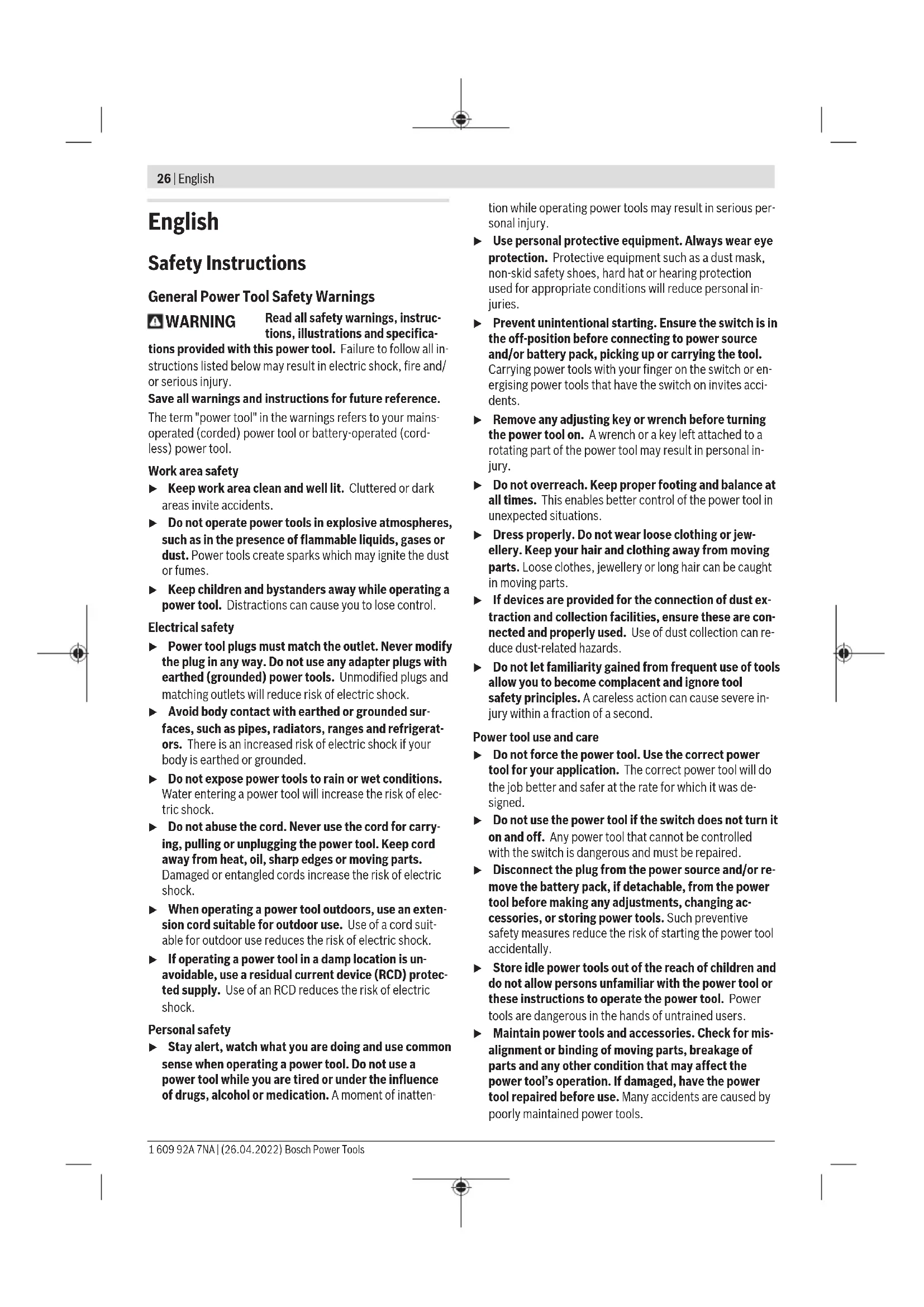
äußeren Abmessung größer als 25cm sind, im Einzel- handelsgeschäft oder in unmittelbarer Nähe hierzu un- entgeltlich zurückzunehmen; die Rücknahme darf nicht an den Kauf eines Elektro- oder Elektronikgerätes ge- knüpft werden und ist auf drei Altgeräte pro Geräteart beschränkt. Der Vertreiber hat beim Abschluss des Kaufvertrags für das neue Elektro- oder Elektronikgerät den Endnutzer über die Möglichkeit zur unentgeltlichen Rückgabe bzw. Abholung des Altgeräts zu informieren und den Endnutzer nach seiner Absicht zu befragen, ob bei der Auslieferung des neuen Ge- räts ein Altgerät zurückgegeben wird. Dies gilt auch bei Vertrieb unter Verwendung von Fernkom- munikationsmitteln, wenn die Lager- und Versandflächen für Elektro- und Elektronikgeräte mindestens 400m² betragen oder die gesamten Lager- und Versandflächen mindestens 800m² betragen, wobei die unentgeltliche Abholung auf Elektro- und Elektronikgeräte der Kategorien 1 (Wärmeüber- träger), 2 (Bildschirmgeräte) und 4 (Großgeräte mit mindes- tens einer äußeren Abmessung über 50cm) beschränkt ist. Für alle übrigen Elektro- und Elektronikgeräte muss der Ver- treiber geeignete Rückgabemöglichkeiten in zumutbarer Ent- fernung zum jeweiligen Endnutzer gewährleisten; das gilt auch für Altgeräte, die in keiner äußeren Abmessung größer als 25cm sind, die der Endnutzer zurückgeben will, ohne ein neues Gerät zu kaufen. Bosch Power Tools 1 609 92A 7NA | (26.04.2022)26 | English English Safety Instructions General Power Tool Safety Warnings WARNING Read all safety warnings, instruc- tions, illustrations and specifica- tions provided with this power tool. Failure to follow all in- structions listed below may result in electric shock, fire and/ or serious injury. Save all warnings and instructions for future reference. The term "power tool" in the warnings refers to your mains- operated (corded) power tool or battery-operated (cord- less) power tool. Work area safety u Keep work area clean and well lit. Cluttered or dark areas invite accidents. u Do not operate power tools in explosive atmospheres, such as in the presence of flammable liquids, gases or dust. Power tools create sparks which may ignite the dust or fumes. u Keep children and bystanders away while operating a power tool. Distractions can cause you to lose control. Electrical safety u Power tool plugs must match the outlet. Never modify the plug in any way. Do not use any adapter plugs with earthed (grounded) power tools. Unmodified plugs and matching outlets will reduce risk of electric shock. u Avoid body contact with earthed or grounded sur- faces, such as pipes, radiators, ranges and refrigerat- ors. There is an increased risk of electric shock if your body is earthed or grounded. u Do not expose power tools to rain or wet conditions. Water entering a power tool will increase the risk of elec- tric shock. u Do not abuse the cord. Never use the cord for carry- ing, pulling or unplugging the power tool. Keep cord away from heat, oil, sharp edges or moving parts. Damaged or entangled cords increase the risk of electric shock. u When operating a power tool outdoors, use an exten- sion cord suitable for outdoor use. Use of a cord suit- able for outdoor use reduces the risk of electric shock. u If operating a power tool in a damp location is un- avoidable, use a residual current device (RCD) protec- ted supply. Use of an RCD reduces the risk of electric shock. Personal safety u Stay alert, watch what you are doing and use common sense when operating a power tool. Do not use a power tool while you are tired or under the influence of drugs, alcohol or medication. A moment of inatten- tion while operating power tools may result in serious per- sonal injury. u Use personal protective equipment. Always wear eye protection. Protective equipment such as a dust mask, non-skid safety shoes, hard hat or hearing protection used for appropriate conditions will reduce personal in- juries. u Prevent unintentional starting. Ensure the switch is in the off-position before connecting to power source and/or battery pack, picking up or carrying the tool. Carrying power tools with your finger on the switch or en- ergising power tools that have the switch on invites acci- dents. u Remove any adjusting key or wrench before turning the power tool on. A wrench or a key left attached to a rotating part of the power tool may result in personal in- jury. u Do not overreach. Keep proper footing and balance at all times. This enables better control of the power tool in unexpected situations. u Dress properly. Do not wear loose clothing or jew- ellery. Keep your hair and clothing away from moving parts. Loose clothes, jewellery or long hair can be caught in moving parts. u If devices are provided for the connection of dust ex- traction and collection facilities, ensure these are con- nected and properly used. Use of dust collection can re- duce dust-related hazards. u Do not let familiarity gained from frequent use of tools allow you to become complacent and ignore tool safety principles. A careless action can cause severe in- jury within a fraction of a second. Power tool use and care u Do not force the power tool. Use the correct power tool for your application. The correct power tool will do the job better and safer at the rate for which it was de- signed. u Do not use the power tool if the switch does not turn it on and off. Any power tool that cannot be controlled with the switch is dangerous and must be repaired. u Disconnect the plug from the power source and/or re- move the battery pack, if detachable, from the power tool before making any adjustments, changing ac- cessories, or storing power tools. Such preventive safety measures reduce the risk of starting the power tool accidentally. u Store idle power tools out of the reach of children and do not allow persons unfamiliar with the power tool or these instructions to operate the power tool. Power tools are dangerous in the hands of untrained users. u Maintain power tools and accessories. Check for mis- alignment or binding of moving parts, breakage of parts and any other condition that may affect the power tool’s operation. If damaged, have the power tool repaired before use. Many accidents are caused by poorly maintained power tools. 1 609 92A 7NA | (26.04.2022) Bosch Power ToolsEnglish | 27 u Keep cutting tools sharp and clean. Properly main- tained cutting tools with sharp cutting edges are less likely to bind and are easier to control. u Use the power tool, accessories and tool bits etc. in accordance with these instructions, taking into ac- count the working conditions and the work to be per- formed. Use of the power tool for operations different from those intended could result in a hazardous situation. u Keep handles and grasping surfaces dry, clean and free from oil and grease. Slippery handles and grasping surfaces do not allow for safe handling and control of the tool in unexpected situations. Service u Have your power tool serviced by a qualified repair person using only identical replacement parts. This will ensure that the safety of the power tool is maintained. Safety Warnings for Mitre Saws u Mitre saws are intended to cut wood or wood-like products, they cannot be used with abrasive cut-off wheels for cutting ferrous material such as bars, rods, studs, etc. Abrasive dust causes moving parts such as the lower guard to jam. Sparks from abrasive cutting will burn the lower guard, the kerf insert and other plastic parts. u Use clamps to support the workpiece whenever pos- sible. If supporting the workpiece by hand, you must always keep your hand at least 100 mm from either side of the saw blade. Do not use this saw to cut pieces that are too small to be securely clamped or held by hand. If your hand is placed too close to the saw blade, there is an increased risk of injury from blade contact. u The workpiece must be stationary and clamped or held against both the fence and the table. Do not feed the workpiece into the blade or cut “freehand” in any way. Unrestrained or moving workpieces could be thrown at high speeds, causing injury. u Push the saw through the workpiece. Do not pull the saw through the workpiece. To make a cut, raise the saw head and pull it out over the workpiece without cutting, start the motor, press the saw head down and push the saw through the workpiece. Cutting on the pull stroke is likely to cause the saw blade to climb on top of the workpiece and violently throw the blade assembly towards the operator. u Never cross your hand over the intended line of cut- ting either in front or behind the saw blade. Supporting the workpiece “cross handed” i.e. holding the workpiece to the right of the saw blade with your left hand or vice versa is very dangerous. u Do not reach behind the fence with either hand closer than 100 mm from either side of the saw blade, to re- move wood scraps, or for any other reason while the blade is spinning. The proximity of the spinning saw blade to your hand may not be obvious and you may be seriously injured. u Inspect your workpiece before cutting. If the work- piece is bowed or warped, clamp it with the outside bowed face toward the fence. Always make certain that there is no gap between the workpiece, fence and table along the line of the cut. Bent or warped work- pieces can twist or shift and may cause binding on the spinning saw blade while cutting. There should be no nails or foreign objects in the workpiece. u Do not use the saw until the table is clear of all tools, wood scraps, etc., except for the workpiece. Small debris or loose pieces of wood or other objects that con- tact the revolving blade can be thrown with high speed. u Cut only one workpiece at a time. Stacked multiple workpieces cannot be adequately clamped or braced and may bind on the blade or shift during cutting. u Ensure the mitre saw is mounted or placed on a level, firm work surface before use. A level and firm work sur- face reduces the risk of the mitre saw becoming unstable. u Plan your work. Every time you change the bevel or mitre angle setting, make sure the adjustable fence is set correctly to support the workpiece and will not in- terfere with the blade or the guarding system. Without turning the tool “ON” and with no workpiece on the table, move the saw blade through a complete simulated cut to assure there will be no interference or danger of cutting the fence. u Provide adequate support such as table extensions, saw horses, etc. for a workpiece that is wider or longer than the table top. Workpieces longer or wider than the mitre saw table can tip if not securely supported. If the cut-off piece or workpiece tips, it can lift the lower guard or be thrown by the spinning blade. u Do not use another person as a substitute for a table extension or as additional support. Unstable support for the workpiece can cause the blade to bind or the workpiece to shift during the cutting operation pulling you and the helper into the spinning blade. u The cut-off piece must not be jammed or pressed by any means against the spinning saw blade. If confined, i.e. using length stops, the cut-off piece could get wedged against the blade and thrown violently. u Always use a clamp or a fixture designed to properly support round material such as rods or tubing. Rods have a tendency to roll while being cut, causing the blade to “bite” and pull the work with your hand into the blade. u Let the blade reach full speed before contacting the workpiece. This will reduce the risk of the workpiece be- ing thrown. u If the workpiece or blade becomes jammed, turn the mitre saw off. Wait for all moving parts to stop and disconnect the plug from the power source and/or re- move the battery pack. Then work to free the jammed material. Continued sawing with a jammed workpiece could cause loss of control or damage to the mitre saw. u After finishing the cut, release the switch, hold the saw head down and wait for the blade to stop before Bosch Power Tools 1 609 92A 7NA | (26.04.2022)28 | English removing the cut-off piece. Reaching with your hand near the coasting blade is dangerous. u Hold the handle firmly when making an incomplete cut or when releasing the switch before the saw head is completely in the down position. The braking action of the saw may cause the saw head to be suddenly pulled downward, causing a risk of injury. u Do not let go of the handle once the saw head has reached the lowest position. Always guide the saw head back to the top position by hand. There is a risk of injury if the saw head moves in an uncontrolled manner. u Keep your work area clean. Material mixtures are partic- ularly hazardous. Light metal dust may catch fire or ex- plode. u Do not use dull, cracked, bent or damaged saw blades. Unsharpened or improperly set saw blades produce narrow kerf causing excessive friction, blade binding and kickback. u Do not use saw blades made from high speed steel (HSS). Such saw blades can easily break. u Always use saw blades with correct size and shape (diamond versus round) of arbour holes. Saw blades that do not match the mounting hardware of the saw will run off-centre, causing loss of control. u Never remove cuttings, wood chips, etc. from the cut- ting area while the power tool is running. Always guide the tool arm back to the neutral position first and then switch the power tool off. u Do not touch the saw blade after working before it has cooled. The saw blade becomes very hot while working. Products sold in GB only: Your product is fitted with an BS 1363/A approved electric plug with internal fuse (ASTA approved to BS 1362). If the plug is not suitable for your socket outlets, it should be cut off and an appropriate plug fitted in its place by an au- thorised customer service agent. The replacement plug should have the same fuse rating as the original plug. The severed plug must be disposed of to avoid a possible shock hazard and should never be inserted into a mains socket elsewhere. u Never make warning signs on the machine unrecognis- able. u The power tool is delivered with a laser warning sign (see table: "Symbols and their meaning"). Do not direct the laser beam at persons or animals and do not stare into the direct or reflected laser beam yourself. You could blind somebody, cause accidents or damage your eyes. u If laser radiation hits your eye, you must close your eyes and immediately turn your head away from the beam. u Do not use any optical instruments such as binoculars to view the radiation source. Doing so can damage your eye. u Do not direct the laser beam at persons who are look- ing through binoculars or similar instruments. Doing so can damage their eye. u Do not make any modifications to the laser equip- ment. The setting options described in these operating instructions can be used safely. u Do not use the laser goggles (accessory) as protective goggles. The laser goggles make the laser beam easier to see; they do not protect you against laser radiation. u Do not use the laser goggles (accessory) as sunglasses or while driving. The laser goggles do not provide full UV protection and impair your ability to see colours. u Warning! If operating or adjustment devices other than those specified here are used or other proced- ures are carried out, this can lead to dangerous expos- ure to radiation. u Do not replace the integrated laser with a laser of an- other type. A laser that is not compatible with this power tool could pose a risk to persons. Symbols The following symbols may be important for the operation of your power tool. Please take note of these symbols and their meaning. Correctly interpreting the symbols will help you to operate the power tool more effectively and safely. Symbols and their meaning IEC 60825-1:2014 <0.39mW, 650 nm LASER RADIATION
Keep hands away from the cutting area while the power tool is running. Con- tact with the saw blade can lead to injur- ies. Wear a dust mask. Wear safety goggles. Wear hearing protection. Exposure to noise can cause hearing loss. Danger area! Keep hands, fingers and arms away from this area. 1 609 92A 7NA | (26.04.2022) Bosch Power ToolsEnglish | 29 Symbols and their meaning
The table shows the recommended speed setting depending on the material to be worked: Aluminium, plastic, wood. When sawing bevel angles, the adjustable fences must be pulled outwards or re- moved completely. 3601M192.. 3601M192B. 25,4 Observe the dimensions of the saw blade. The hole diameter must match the tool spindle without play. If it is neces- sary to use reducers, ensure that the di- mensions of the reducer are suitable for the base blade thickness and the saw blade hole diameter, as well as the tool spindle diameter. Wherever possible, use the reducers provided with the saw blade. The saw blade diameter must match the information specified on the symbol. Shows the rotational direction of the SDS bolt for tightening the saw blade (anti- clockwise) and for loosening the saw blade (clockwise). Clamping lever closed: The adjusted bevel angle of the tool arm is held in place. Clamping lever open: Bevel angles can be adjusted. Product Description and Specifications Read all the safety and general instructions. Failure to observe the safety and general in- structions may result in electric shock, fire and/or serious injury. Please observe the illustrations at the beginning of this oper- ating manual. Intended Use The power tool is intended as a stationary machine for mak- ing straight cuts in wood with and against the grain. It is pos- sible to cut mitre angles of -52° to +60° and bevel angles of 47° (to the left) to 47° (to the right). The power tool is designed with sufficient capacity for saw- ing hardwood and softwood as well as chipboard and fibre- board. When using appropriate saw blades, sawing aluminium pro- files and plastic is also possible. Product features The numbering of the product features refers to the diagram of the power tool on the graphics page. (1) Slide device (2) Chip ejector (3) Transport handle (4) Depth stop adjusting screw (5) Laser protection cap (6) Guide roller (7) Lock-off function for on/off switch (8) On/off switch (9) Handle (10) Protective guard (11) Retracting blade guard (12) Saw blade (13) Saw table extension (14) Fence (15) Adjustable fence (16) Saw table (17) Clamping lever of the saw table extension (18) Scale for mitre angles (19) Insert plate (20) Locking clamp (21) Locking knob for various mitre angles (22) Mitre pre-setting lever (23) Tilt protector (24) Angle indicator for mitre angles (25) Detents for standard mitre angles (26) Mounting holes (27) Recessed handles (28) Screw clamp (29) Standard bevel angle stops 45°, 22.5° and 33.9° (30) Scale for bevel angle (31) Angle indicator for right-hand bevel angle range (32) Depth stop (33) Locking screw for slide device (34) Hex key (5mm) (35) Holes for screw clamp (36) Length stop
(37) Transport safety lock (38) Speed regulator (39) Laser warning label (40) On/off switch for laser (cutting line indication) (41) Clamping lever for all bevel angles (42) Angle indicator for left-hand bevel angle range (43) Chip deflector (44) Stop for standard 0° bevel angle Bosch Power Tools 1 609 92A 7NA | (26.04.2022)30 | English (45) Spindle lock (46) Hex socket screw for mounting the saw blade (47) Clamping flange (48) Laser beam outlet aperture (49) Inner clamping flange (50) SDS bolt (51) Locking screw for the adjustable fence (52) Threaded rod (53) Locking screw for length stop
(54) Clamping screw for length gauge
Accessories shown or described are not included with the product as standard. You can find the complete selection of accessories in our accessories range. Technical data Sliding mitre saw GCM 8 SDE GCM 8 SDE Article number 3601M192.. 3601M192B. Rated power input W 1600 1400 No-load speed min
3500–5300 3500–5300 Starting current limitation ● ● Laser type nm 650 650 mW <0.39 <0.39 Laser class 1M 1M Divergence of laser line mrad (full angle) 1.0 1.0 Weight according to EPTA-Proced- ure01:2014 kg 18.9 18.9 Protection class / II / II Dimensions of suitable saw blades Saw blade diameter mm 216 216 Base blade thickness mm 1.3–1.8 1.3–1.8 Max. cutting width mm 3.3 3.3 Hole diameter mm 30 25.4 Permissible workpiece dimensions (see "Permissible workpiece dimensions", page35) The specifications apply to a rated voltage [U] of 230 V. These specifications may vary at different voltages and in country-specific models. Noise Information Noise emission values determined according to EN62841-3-9. Typically, the A-weighted noise level of the power tool is: Sound pressure level 98dB(A); sound power level 108dB(A). Uncertainty K = 3dB. Wear hearing protection! The noise emission value given in these instructions has been measured in accordance with a standardised measur- ing procedure and may be used to compare power tools. It may also be used for a preliminary estimation of noise emis- sions. The noise emission value given represents the main applica- tions of the power tool. However, if the power tool is used for other applications, with different application tools or is poorly maintained, the noise emission value may differ. This may significantly increase noise emissions over the total working period. To estimate noise emissions accurately, the times when the tool is switched off, or when it is running but not actually be- ing used, should also be taken into account. This may signi- ficantly reduce noise emissions over the total working period. Assembly u Avoid starting the power tool unintentionally. The mains plug must not be connected to the power supply during assembly or when carrying out any kind of work on the power tool. 1 609 92A 7NA | (26.04.2022) Bosch Power ToolsEnglish | 31 Items included See the list of items included at the start of the operating manual. Check to ensure that all the parts listed below have been supplied before using the power tool for the first time: – Sliding mitre saw with mounted saw blade – Screw clamp (28) – Hex key (34) – SDS bolt (50) Note: Check the power tool for possible damage. Before continuing to use the power tool, carefully check that all protective devices or slightly damaged parts are working perfectly and according to specifications. Check that the moving parts are working perfectly and without jamming; check whether any parts are damaged. All parts must be fit- ted correctly and all the conditions necessary to ensure smooth operation must be met. If the protective devices or any parts become damaged, you must have them properly repaired or replaced by an author- ised service centre. Extra tools required (not included in the delivery): – Cross-headed screwdriver – Ring spanner or open-ended spanner (size: 10mm) Stationary or flexible mounting u To ensure safe handling, the power tool must be mounted on a flat, stable work surface (e.g. work bench) before use. Mounting on a work surface (see figure A1−A2) – Use suitable screw fasteners to secure the power tool to the work surface. The holes (26) are used for this pur- pose.
– Firmly clamp the base of the power tool to the work sur- face with commercially available screw clamps. Mounting on a Bosch saw stand With the height-adjustable legs, Bosch GTA saw stands provide firm support for the power tool on any surface. The workpiece supports of the saw stand are used for underlay- ing long workpieces. u Read all the warnings and instructions included with the saw stand. Failure to observe the warnings and fol- low instructions may result in electric shock, fire and/or serious injury. u Assemble the saw stand properly before mounting the power tool. Correct assembly is important to prevent the risk of collapsing. – Mount the power tool on the saw stand in the transport position. Flexible installation (not recommended) (see figure A3) If, in exceptional circumstances, it is not possible to mount the power tool on a flat and stable work surface, you can im- provise by setting it up with the tilt protector. u Without the tilt protector, the power tool will not be stable and can tip over especially when sawing max- imum mitre and/or bevel angles. – Rotate the tilt protector (23) inwards or outwards until the power tool is positioned straight on the work surface. Dust/Chip Extraction The dust from materials such as lead paint, some types of wood, minerals and metal can be harmful to human health. Touching or breathing in this dust can trigger allergic reac- tions and/or cause respiratory illnesses in the user or in people in the near vicinity. Certain dusts, such as oak or beech dust, are classified as carcinogenic, especially in conjunction with wood treatment additives (chromate, wood preservative). Materials contain- ing asbestos may only be machined by specialists. – Use a dust extraction system that is suitable for the ma- terial wherever possible. – Provide good ventilation at the workplace. – It is advisable to wear a P2 filter class breathing mask. The regulations on the material being machined that apply in the country of use must be observed. u Avoid dust accumulation at the workplace. Dust can easily ignite. The dust/chip extraction system can be blocked by dust, chips or fragments of the workpiece. – Switch the power tool off and pull the mains plug out of the socket. – Wait until the saw blade has come to a complete stop. – Determine the cause of the blockage and eliminate it. External Dust Extraction You can also attach a dust extraction hose (35 mm dia- meter) to the chip ejector (2) for extraction. – Connect the dust extraction hose to the chip ejector (2). The dust extractor must be suitable for the material being worked. When extracting dry dust that is especially detrimental to health or carcinogenic, use a special dust extractor. Changing the Saw Blade u Pull the plug out of the socket before carrying out any work on the power tool. u Wear protective gloves when fitting the saw blade. There is a risk of injury when touching the saw blade. Only use saw blades that have a maximum permitted speed higher than the no-load speed of the power tool. Only use saw blades that match the specifications given in this operating manual and that have been tested and marked in accordance with EN847-1. Only use saw blades that are recommended by the power tool manufacturer and are suitable for use on the material Bosch Power Tools 1 609 92A 7NA | (26.04.2022)32 | English you want to saw. This will prevent the saw teeth overheating when sawing. Assembly with hex socket screw (see figures B1−B4) Removing the saw blade – Bring the power tool into the work position. – Turn the hex socket screw (46) using the hex key (34) while pressing the spindle lock (45) until it engages. – Press and hold the spindle lock (45) and loosen the screw (46) by turning it clockwise (left-hand thread). – Remove the clamping flange (47). – Swivel the retracting blade guard (11) backwards as far as possible. – Hold the retracting blade guard in this position and re- move the saw blade (12). – Slowly push the retracting blade guard back down. Fitting the saw blade u When fitting the saw blade, make sure that the cutting direction of the teeth (arrow direction on the saw blade) matches the direction of the arrow on the pro- tective guard. If required, clean all the parts you want to fit before installing them. – Swivel the retracting blade guard(11) to the back and hold it in this position. – Place the new saw blade on the inner clamping flange(49). – Fit the clamping flange(47) and the hex socket screw(46). Press the spindle lock(45) until it engages and tighten the hex socket screw by turning it anticlock- wise. – Slowly push the retracting blade guard back down. Assembly with SDS bolt (see figure C) u For bevel cuts when using the SDS bolt(50), before sawing, first make sure that the SDS bolt cannot come into contact with the surface of the workpiece at any time by making a suitable adjustment to the depth stop (32). This prevents damage to the SDS bolt and/or the workpiece. Removing the saw blade – Bring the power tool into the work position. – Press and hold the spindle lock (45) and unscrew the SDS bolt (50) by turning it clockwise (left-hand thread). – Remove the clamping flange (47). – Swivel the retracting blade guard (11) backwards as far as possible. – Hold the retracting blade guard in this position and re- move the saw blade (12). – Slowly push the retracting blade guard back down. Fitting the saw blade u When fitting the saw blade, make sure that the cutting direction of the teeth (arrow direction on the saw blade) matches the direction of the arrow on the pro- tective guard. If required, clean all the parts to be fitted before installing them. – Swivel the retracting blade guard (11) backwards. Hold the retracting blade guard in this position. – Place the new saw blade onto the interior clamping flange (49). – Slowly push the retracting blade guard back down. – Attach the clamping flange (47) and the SDS bolt (50). Press the spindle lock (45) until it engages and tighten the SDS bolt by turning it anticlockwise. Operation u Pull the plug out of the socket before carrying out any work on the power tool. Transport Safety Lock (see figureD) The transport safety lock(37) makes it easier to handle the power tool when transporting it to various working locations. Unlocking the power tool (work position) – Press the tool arm down slightly by the handle (9) to re- lease the transport safety lock (37). – Pull the transport safety lock (37) all the way out. – Slowly guide the tool arm upwards. Locking the power tool (transport position) – Loosen the locking screw (33) if it is clamping the slide device (1) in place. Pull the tool arm fully forward and tighten the locking screw again to lock the slide device. – Screw the adjusting screw (4) all the way upwards. – To lock the saw table (16) in place, tighten the locking knob (21). – Swing the tool arm downwards by the handle (9) until you can press the transport safety lock (37) completely in- wards. The tool arm is now securely locked and ready for transport- ation. Preparing for operation Extending the saw table (see figure E) The free end of long workpieces must have something placed underneath it or be supported. The saw table can be extended left and right using the saw table extensions (13). – Pull the clamping lever (17) upwards. – Pull out the saw table extension (13) to the required length. – To lock the saw table extension, push the clamping lever (17) back down. Moving the Fence (see figureF) When sawing mitre and/or bevel angles, you have to pull the left-hand or right-hand adjustable fence(15) outwards depending on the cutting direction, or remove it completely. 1 609 92A 7NA | (26.04.2022) Bosch Power ToolsEnglish | 33 Bevel angle Mitre angle 0°–47° (left) ≤44° (right/left) – Loosen the locking screw(51). – Pull the left-hand adjustable fence(15) all the way out. 0°–47° (left) ≥45° (right/left) – Loosen the locking screw(51). – Pull the left-hand adjustable fence(15) all the way out. – Lift the adjustable fence upwards and out of the way. – Remove the locking screw(51). 0°–47° (right) ≤44° (right/left) – Loosen the locking screw(51). – Pull the right-hand adjustable fence(15) all the way out. – Lift the adjustable fence upwards and out of the way. 0°–47° (right) ≥45° (right/left) Clamping the Workpiece (see figureG) To ensure maximum safety while working, the workpiece must always be firmly clamped. Do not saw workpieces that are too small to clamp firmly. – Press the workpiece firmly against the fences(15) and(14). – Insert the supplied screw clamp(28) into one of the cor- responding holes(35). – Adjust the threaded rod(52) of the screw clamp to the workpiece height. – Tighten the threaded rod(52) to fix the workpiece in place. Setting mitre and bevel angles To ensure precise cuts, the basic settings of the power tool must be checked and adjusted as necessary after intensive use. Experience and suitable special tools are required for this. A Bosch after-sales service point will handle this work quickly and reliably. u Always tighten the locking knob(21) and the clamp- ing lever (41) firmly before sawing. Otherwise the saw blade can become wedged in the workpiece. Note for adjusting mitre angles >45°: Before adjusting the mitre angle, pull the saw table extension(13) and the adjustable fence(15) all the way out. u For bevel cuts when using the SDS bolt(50), before sawing, first make sure that the SDS bolt cannot come into contact with the surface of the workpiece at any time by making a suitable adjustment to the depth stop (32). This prevents damage to the SDS bolt and/or the workpiece. Setting Standard Mitre Angles (see figure H) For quick and precise setting of commonly used mitre angles, detents (25) are provided on the saw table: Leftward Rightward
45°; 31.6°; 22.5°; 15° 15°; 22.5°; 31.6°; 45°; 60° – Loosen the locking knob (21) if it is tightened. – Pull the lever (22) and rotate the saw table (16) left or right to the required detent. – Release the lever again. The lever must be felt to engage in the detent. – Retighten the locking knob (21). Setting Any Mitre Angle (see figure I) The mitre angle can be set between 52° (left side) and 60° (right side). – Loosen the locking knob (21) if it is tightened. – Pull the lever (22) and at the same time press the locking clamp (20) until this clicks into the slot provided for it. This means the saw table can now move freely. – Turn the saw table (16) left or right by the locking knob until the angle indicator (24) shows the required mitre angle. – Retighten the locking knob (21). – To loosen the lever (22) again (for setting standard mitre angles), pull the lever upwards. The locking clamp (20) springs back into its original posi- tion and the lever (22) can click back into the detents (25). Setting the Complete Bevel Angle Range (see figureJ) The bevel angle can be set between 47° (left side) and 47° (right side). – Pull the stop(44) all the way forward. This enables you to use the complete bevel angle range (left and right). – Pull the right-hand adjustable fence(15) all the way out or remove it completely . If you want to use the entire bevel angle range, you also have to pull the left-hand adjustable fence(15) all the way out or remove it completely. – Loosen the clamping lever(41). – Swivel the tool arm left or right by the handle(9) until the angle indicator(42)/(31) shows the required bevel angle. – Retighten the clamping lever(41). Setting Standard Bevel Angles (see figure K) For quick and precise setting of frequently used bevel angles, stops have been provided for the angles 0°, 45°, 22.5° and 33.9°. Bosch Power Tools 1 609 92A 7NA | (26.04.2022)34 | English – Standard 0° bevel angles: Swing the tool arm by the handle(9) slightly to the left and swing the stop(44) all the way back. Standard 45°, 33.9° and 22.5° bevel angles: Turn the left-hand or right-hand stop(29) until the re- quired standard bevel angle engages at the arrow mark. Start-up u Products that are only sold in AUS and NZ: Use a resid- ual current device (RCD) with a nominal residual current of 30 mA or less. u Pay attention to the mains voltage. The voltage of the power source must match the voltage specified on the rating plate of the power tool. Power tools marked with 230V can also be operated with 220V. Switching on (see figureL) – To switch on the power tool, first slide the lock-off button(7) to the middle and then press and hold the on/ off switch(8). Note: For safety reasons, the on/off switch (8) cannot be locked; it must remain pressed during the entire operation. Switching off – To switch off, release the on/off switch (8). Starting current limitation The electronic starting current limitation feature restricts the power of the power tool when it is switched on and enables operation using a 16 A fuse. Note: If the power tool runs at full speed immediately after being switched on, this means that the starting current limit- ation has failed. The power tool must be sent to the after- sales service without delay. Sawing General sawing instructions u Always tighten the locking knob(21) and the clamp- ing lever (41) firmly before sawing. Otherwise the saw blade can become wedged in the workpiece. u For all cuts, it must first be ensured that the saw blade at no time can come in contact with the fence, screw clamps or other machine parts. Remove any mounted auxiliary stops or adjust them accordingly. Protect the saw blade against impact and shock. Do not sub- ject the saw blade to lateral pressure. Only saw materials which are permitted within the scope of the intended use. Do not saw warped/bent workpieces. The workpiece must always have a straight edge to face against the fence. The free end of long and heavy workpieces must have some- thing placed underneath it or be supported. Make sure that the retracting blade guard operates properly and that it can move freely. The retracting blade guard must open when the tool arm is guided downwards. When the tool arm is guided upwards, the retracting blade guard must close again over the saw blade and lock in the uppermost po- sition of the tool arm. Adjusting the speed The speed regulator(38) enables continuously variable ad- justment of the speed of the power tool even during opera- tion. Note: Always set the suitable speed for the workpiece ma- terial (see table below). This will prevent the saw teeth over- heating when sawing. Speed setting Speed Material 1 3500 rpm Aluminium 2 3800 rpm 3 4100 rpm Plastics 4 4400 rpm 5 4700 rpm Wood 6 5300 rpm Position of the operator (see figure M) u Do not stand in line with the saw blade in front of the power tool. Always stand to the side of the saw blade. This protects your body against possible kickback. – Keep hands, fingers and arms away from the rotating saw blade. – Do not reach one hand across the other when in front of the tool arm. Sawing with slide movement – For cuts made using the slide device(1) (wide work- pieces), loosen the locking screw(33) if it is clamping the slide device in place. – Firmly clamp the workpiece as appropriate for its dimen- sions. – Set the required mitre and/or bevel angle. – Pull the tool arm away from the fences(15) and until the saw blade is in front of the workpiece. – Switch on the power tool. – Slowly guide the tool arm downwards using the handle(9). – Now push the tool arm towards the fences(15) and and saw through the workpiece with uniform feed. – Switch off the power tool and wait until the saw blade has come to a complete stop. – Slowly guide the tool arm upwards. Sawing Without Slide Movement (cutting off) (see figureN) – To perform cuts without slide movement (small work- pieces), loosen the locking screw(33) if it is clamping the slide device(1) in place. Push the tool arm all the way to- wards the fences(15) and and retighten the locking screw(33) to lock the slide device in place. – Firmly clamp the workpiece as appropriate for its dimen- sions. – Set the required mitre and/or bevel angle. – Switch on the power tool. – Slowly guide the tool arm downwards using the handle(9). 1 609 92A 7NA | (26.04.2022) Bosch Power ToolsEnglish | 35 – Saw through the workpiece applying uniform feed. – Switch off the power tool and wait until the saw blade has come to a complete stop. – Slowly guide the tool arm upwards. Practical advice Marking the Cutting Line (see figureO) A laser beam shows you the cutting line of the saw blade. This allows for exact positioning of the workpiece for sawing, without having to open the retracting blade guard. – To activate this, turn on the laser beam using the switch(40). – Align your mark on the workpiece with the right-hand edge of the laser line. Note: Before sawing, check whether the cutting line is still indicated correctly. The laser beam can be misaligned due to vibrations from intensive use, for example. Permissible workpiece dimensions Maximum workpiece dimensions: Mitre angle Bevel angle Height x width [mm] 0° 0° 70 x 312 45° (right/left) 0° 70 x 225 0° 45° (left) 45 x 312 0° 45° (right) 20 x 312 45° 45° (left) 45 x 225 45° 45° (right) 20 x 225 45° (right/left) 45° (left with SDS bolt) 30 x 225 Minimum workpiece dimensions (= all workpieces that can be secured left or right of the saw blade using the supplied screw clamps (28)): 100 x 40 mm (length x width) Max. cutting depth (0°/0°): 70 mm Adjusting the depth stop (sawing the groove) (see figure
www.bosch-pt.com/serviceaddresses
EU Declaration of Conformity We declare under our sole responsibility that the stated products comply with all applicable provisions of the directives and regulations listed below and are in conformity with the following standards. Technical file at: * Sliding mitre saw Article number
We declare under our sole responsibility that the stated products comply with all applicable provisions of the regulations lis- ted below and are in conformity with the following standards. Technical file at: Robert Bosch Ltd. (PT/SOP-GB), Broadwater Park, North Orbital Road, Uxbridge UB9 5HJ, United Kingdom The Supply of Machinery (Safety) Regulations 2008 The Electromagnetic Compatibility Regulations 2016 The Restriction of the Use of Certain Hazardous Substances in Electrical and Electronic Equipment Regulations 2012 EN 62841-1:2015
EN 61000-3-3:2013+A1:2019 EN IEC 63000:2018 Robert Bosch Power Tools GmbH, 70538 Stuttgart, Germany represented (in terms of the above regulations) by Robert Bosch Limited, Broadwater Park, North Orbital Road, Uxbridge UB9 5HJ, United Kingdom Vonjy Rajakoba Managing Director - Bosch UK Martin Sibley Head of Sales Operations and Aftersales Robert Bosch Ltd. Broadwater Park, North Orbital Road, Uxbridge UB9 5HJ, United Kingdom, as authorised representative acting on behalf of Robert Bosch Power Tools GmbH, 70538 Stuttgart, Germany Place of issue: Uxbridge Date of issue: 06/05/2021 Bosch Power Tools 1 609 92A 7NA | (26.04.2022)