GCO 240 Professional - Saw BOSCH - Free user manual and instructions
Find the device manual for free GCO 240 Professional BOSCH in PDF.
Download the instructions for your Saw in PDF format for free! Find your manual GCO 240 Professional - BOSCH and take your electronic device back in hand. On this page are published all the documents necessary for the use of your device. GCO 240 Professional by BOSCH.
USER MANUAL GCO 240 Professional BOSCH
OBJ_BUCH-2660-003.book Page 2 Tuesday, July 19, 2016 9:50 AM| 3 Bosch Power Tools 1 609 92A 34C | (19.7.16)
OBJ_BUCH-2660-003.book Page 3 Tuesday, July 19, 2016 9:50 AM1 609 92A 34C | (19.7.16) Bosch Power Tools 4 |
B1A OBJ_BUCH-2660-003.book Page 4 Tuesday, July 19, 2016 9:50 AM| 5 Bosch Power Tools 1 609 92A 34C | (19.7.16)
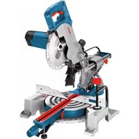
OBJ_BUCH-2660-003.book Page 5 Tuesday, July 19, 2016 9:50 AM6 | English 1 609 92A 34C | (19.7.16) Bosch Power Tools English Safety Notes General Power Tool Safety Warnings Read all safety warnings, instructions, illustrations and specifications provid- ed with this power tool. Failure to follow all instructions list- ed below may result in electric shock, fire and/or serious inju- ry. Save all warnings and instructions for future reference. The term “power tool” in the warnings refers to your mains- operated (corded) power tool or battery-operated (cordless) power tool. When using electric tools basic safety precautions should always be followed to reduce the risk of fire, electric shock and personal inju- ry including the following. Read all these instructions before attempting to operate this product and save these instructions. Work area safety Keep work area clean and well lit. Cluttered or dark areas invite accidents. Do not operate power tools in explosive atmospheres, such as in the presence of flammable liquids, gases or dust. Power tools create sparks which may ignite the dust or fumes. Keep children and bystanders away while operating a power tool. Distractions can cause you to lose control. Electrical safety Power tool plugs must match the outlet. Never modify the plug in any way. Do not use any adapter plugs with earthed (grounded) power tools. Unmodified plugs and matching outlets will reduce risk of electric shock. Avoid body contact with earthed or grounded surfaces, such as pipes, radiators, ranges and refrigerators. There is an increased risk of electric shock if your body is earthed or grounded. Do not expose power tools to rain or wet conditions. Water entering a power tool will increase the risk of electric shock. Do not abuse the cord. Never use the cord for carrying, pulling or unplugging the power tool. Keep cord away from heat, oil, sharp edges and moving parts. Damaged or entangled cords increase the risk of electric shock. When operating a power tool outdoors, use an exten- sion cord suitable for outdoor use. Use of a cord suitable for outdoor use reduces the risk of electric shock. If operating a power tool in a damp location is unavoid- able, use a residual current device (RCD) protected supply. Use of an RCD reduces the risk of electric shock. Personal safety Stay alert, watch what you are doing and use common sense when operating a power tool. Do not use a power tool while you are tired or under the influence of drugs, alcohol or medication. A moment of inattention while op- erating power tools may result in serious personal injury. Use personal protective equipment. Always wear eye protection. Protective equipment such as dust mask, non-skid safety shoes, hard hat, or hearing protection used for appropriate conditions will reduce personal inju- ries. Prevent unintentional starting. Ensure the switch is in the off-position before connecting to power source and/or battery pack, picking up or carrying the tool. Carrying power tools with your finger on the switch or en- ergising power tools that have the switch on invites acci- dents. Remove any adjusting key or wrench before turning the power tool on. A wrench or a key left attached to a ro- tating part of the power tool may result in personal injury. Do not overreach. Keep proper footing and balance at all times. This enables better control of the power tool in unexpected situations. Dress properly. Do not wear loose clothing or jewel- lery. Keep your hair and clothing away from moving parts. Loose clothes, jewellery or long hair can be caught in moving parts. If devices are provided for the connection of dust ex- traction and collection facilities, ensure these are con- nected and properly used. Use of dust collection can re- duce dust-related hazards. Do not let familiarity gained from frequent use of tools allow you to become complacent and ignore tool safety principles. A careless action can cause severe injury with- in a fraction of a second. Power tool use and care Do not force the power tool. Use the correct power tool for your application. The correct power tool will do the job better and safer at the rate for which it was designed. Do not use the power tool if the switch does not turn it on and off. Any power tool that cannot be controlled with the switch is dangerous and must be repaired. Disconnect the plug from the power source and/or re- move the battery pack, if detachable, from the power tool before making any adjustments, changing acces- sories, or storing power tools. Such preventive safety measures reduce the risk of starting the power tool acci- dentally. Store idle power tools out of the reach of children and do not allow persons unfamiliar with the power tool or these instructions to operate the power tool. Power tools are dangerous in the hands of untrained users. Maintain power tools and accessories. Check for mis- alignment or binding of moving parts, breakage of parts and any other condition that may affect the pow- er tool’s operation. If damaged, have the power tool re- WARNING WARNING OBJ_BUCH-2660-003.book Page 6 Tuesday, July 19, 2016 9:50 AMEnglish | 7 Bosch Power Tools 1 609 92A 34C | (19.7.16) paired before use. Many accidents are caused by poorly maintained power tools. Keep cutting tools sharp and clean. Properly maintained cutting tools with sharp cutting edges are less likely to bind and are easier to control. Use the power tool, accessories and tool bits etc. in ac- cordance with these instructions, taking into account the working conditions and the work to be performed. Use of the power tool for operations different from those intended could result in a hazardous situation. Keep handles and grasping surfaces dry, clean and free from oil and grease. Slippery handles and grasping sur- faces do not allow for safe handling and control of the tool in unexpected situations. Service Have your power tool serviced by a qualified repair per- son using only identical replacement parts. This will en- sure that the safety of the power tool is maintained. Cut-off machine safety warnings Position yourself and bystanders away from the plane of the rotating wheel. The guard helps to protect the op- erator from broken wheel fragments and accidental con- tact with wheel. Use only bonded reinforced cut-off wheels for your power tool. Just because an accessory can be attached to your power tool, it does not assure safe operation. The rated speed of the accessory must be at least equal to the maximum speed marked on the power tool. Ac- cessories running faster than their rated speed can break and fly apart. Wheels must be used only for recommended applica- tions. For example: do not grind with the side of a cut- off wheel. Abrasive cut-off wheels are intended for pe- ripheral grinding, side forces applied to these wheels may cause them to shatter. Always use undamaged wheel flanges that are of cor- rect diameter for your selected wheel. Proper wheel flanges support the wheel thus reducing the possibility of wheel breakage. The outside diameter and the thickness of your acces- sory must be within the capacity rating of your power tool. Incorrectly sized accessories cannot be adequately guarded or controlled. The arbour size of wheels and flanges must properly fit the spindle of the power tool. Wheels and flanges with arbour holes that do not match the mounting hardware of the power tool will run out of balance, vibrate excessively and may cause loss of control. Do not use damaged wheels. Before each use, inspect the wheels for chips and cracks. If the power tool or wheel is dropped, inspect for damage or install an un- damaged wheel. After inspecting and installing the wheel, position yourself and bystanders away from the plane of the rotating wheel and run the power tool at maximum no load speed for one minute. Damaged wheels will normally break apart during this test time. Wear personal protective equipment. Depending on application, use face shield, safety goggles or safety glasses. As appropriate, wear dust mask, hearing pro- tectors, gloves and shop apron capable of stopping small abrasive or workpiece fragments. The eye protec- tion must be capable of stopping flying debris generated by various operations. The dust mask or respirator must be capable of filtrating particles generated by your operation. Prolonged exposure to high intensity noise may cause hearing loss. Keep bystanders a safe distance away from work area. Anyone entering the work area must wear personal protective equipment. Fragments of workpiece or of a broken wheel may fly away and cause injury beyond imme- diate area of operation. Position the cord clear of the spinning accessory. If you lose control, the cord may be cut or snagged and your hand or arm may be pulled into the spinning wheel Regularly clean the power tool’s air vents. The motor’s fan can draw the dust inside the housing and excessive ac- cumulation of powdered metal may cause electrical haz- ards. Do not operate the power tool near flammable materi- als. Do not operate the power tool while placed on a combustible surface such as wood. Sparks could ignite these materials. Do not use accessories that require liquid coolants. Us- ing water or other liquid coolants may result in electrocu- tion or shock. Kickback and related warnings Kickback is a sudden reaction to a pinched or snagged ro- tating wheel. Pinching or snagging causes rapid stalling of the rotating wheel which in turn causes the uncontrolled cutting unit to be forced upwards toward the operator. For example, if an abrasive wheel is snagged or pinched by the workpiece, the edge of the wheel that is entering into the pinch point can dig into the surface of the material causing the wheel to climb out or kick out. Abrasive wheels may also break under these conditions. Kickback is the result of power tool misuse and/or incor- rect operating procedures or conditions and can be avoid- ed by taking proper precautions as given below. Maintain a firm grip on the power tool and position your body and arm to allow you to resist kickback forces. The operator can control upward kickback forces, if proper precautions are taken. Do not position your body in line with the rotating wheel. If kickback occurs, it will propel the cutting unit up- wards toward the operator. Do not attach a saw chain, woodcarving blade, seg- mented diamond wheel with a peripheral gap greater than 10 mm or toothed saw blade. Such blades create frequent kickback and loss of control. Do not “jam” the wheel or apply excessive pressure. Do not attempt to make an excessive depth of cut. Over- stressing the wheel increases the loading and susceptibili- OBJ_BUCH-2660-003.book Page 7 Tuesday, July 19, 2016 9:50 AM8 | English 1 609 92A 34C | (19.7.16) Bosch Power Tools ty to twisting or binding of the wheel in the cut and the pos- sibility of kickback or wheel breakage. When the wheel is binding or when interrupting a cut for any reason, switch off the power tool and hold the cutting unit motionless until the wheel comes to a com- plete stop. Never attempt to remove the wheel from the cut while the wheel is in motion otherwise kickback may occur. Investigate and take corrective action to elim- inate the cause of wheel binding. Do not restart the cutting operation in the workpiece. Let the wheel reach full speed and carefully re-enter the cut. The wheel may bind, walk up or kickback if the power tool is restarted in the workpiece. Support any oversized workpiece to minimize the risk of wheel pinching and kickback. Large workpieces tend to sag under their own weight. Supports must be placed under the workpiece near the line of cut and near the edge of the workpiece on both sides of the wheel. Additional safety warnings Store the machine in a safe manner when not being used. The storage location must be dry and lockable. This prevents the machine from storage damage, and from being operated by untrained persons. Always firmly clamp the workpiece. Do not cut work- pieces that are too small to clamp. Otherwise, the clear- ance of your hand to the rotating cutting disc is too small. Never use the machine with a damaged cable. Do not touch the damaged cable and pull the mains plug when the cable is damaged while working. Damaged cables in- crease the risk of an electric shock. Check the cable regularly and have a damaged cable re- paired only through an authorised customer service agent for Bosch power tools. Replace damaged exten- sion cables. This will ensure that the safety of the power tool is maintained. Always use the blade guard. A blade guard protects the user against broken off parts of the cutting disc and against accidental touching of the cutting disc. Never leave the machine before it has come to a com- plete stop. Cutting tools that are still running can cause in- juries. Products sold in GB only: Your product is fitted with a BS 1363/A approved electric plug with internal fuse (ASTA approved to BS 1362). If the plug is not suitable for your socket outlets, it should be cut off and an appropriate plug fitted in its place by an author- ised customer service agent. The replacement plug should have the same fuse rating as the original plug. The severed plug must be disposed of to avoid a possible shock hazard and should never be inserted into a mains sock- et elsewhere. Products sold in AUS and NZ only: Use a residual current de- vice (RCD) with a rated residual current of 30 mA or less. Symbols The following symbols can be important for the operation of your power tool. Please memorise the symbols and their meanings. The correct interpretation of the symbols helps you operate the power tool better and more safely. Product Description and Specifica- tions Read all safety warnings and all instruc- tions. Failure to follow the warnings and in- structions may result in electric shock, fire and/or serious injury. Intended Use The machine is intended for stationary use with cutting discs to perform lengthways and crossways straight cuts and mitre angles to 45° in metal materials without the use of water. Us- ing diamond-tipped cutting discs is not permitted. Product Features The numbering of the components shown refers to the repre- sentation of the power tool on the graphic pages. 1 Lock-off button for On/Off switch 2 On/Off switch 3 Handle 4 Retracting blade guard 5 Spindle lock 6 Cutting disc Symbol Meaning Keep hands away from the cutting ar- ea while the machine is running. Dan- ger of injury when coming into contact with the cutting disc. Wear ear protectors. Exposure to noise can cause hearing loss. Wear safety goggles. Wear a dust respirator. Wear protective gloves. Cutting discs have sharp edges and be- come very hot during work. OBJ_BUCH-2660-003.book Page 8 Tuesday, July 19, 2016 9:50 AMEnglish | 9 Bosch Power Tools 1 609 92A 34C | (19.7.16) 7 Angle stop 8 Clamping spindle 9 Quick-release button 10 Spindle handle 11 Mounting holes 12 Hex key (8 mm) 13 Base plate 14 Locking screw for angle stop 15 Transport safety-lock 16 Tool arm 17 Transport handle 18 Blade guard 19 Spark guard 20 Tool spindle 21 Clamping flange 22 Washer 23 Hexagon bolt Accessories shown or described are not part of the standard deliv- ery scope of the product. A complete overview of accessories can be found in our accessories program. Technical Data Assembly Delivery Scope Carefully remove all parts included in the delivery from their packaging. Remove all packaging material from the machine and the ac- cessories provided. Before starting the operation of the machine for the first time, check if all parts listed below have been supplied: – Cut-off grinder with mounted cutting disc –Hex key 12 Stationary or Flexible Mounting To ensure safe handling, the machine must be mounted on a level and stable surface (e. g., workbench) prior to using. Mounting to a Working Surface (see figure A) – Fasten the power tool with suitable screw fasteners to the working surface. The mounting holes 11 serve for this pur- pose. Flexible Mounting (not recommended!) In the exceptional case that it should not be possible to firmly bench-mount the power tool, you can provisionally place the legs of base plate 13 on a suitable surface (e. g. a workbench, level floor, etc.) without bolting the machine down. Changing the Tool (see figures B1–B2) Actuate the spindle lock 5 only when the tool spindle 20 is stopped. Otherwise, the machine can become dam- aged. Do not touch the cutting disc after working before it has cooled. The cutting disc becomes very hot while work- ing. Use only cutting discs that correspond to the characteristic data given in these operating instructions and are checked ac- cording to EN 12413 and marked appropriately. Use any intermediate layers provided with the cutting disc. Place unused cutting discs in an enclosed container or in the original packaging. Store cutting discs lying flat. Removing the Cutting Disc – Bring the power tool into the working position. (see “Re- leasing the Machine (Working Position)”, page 10) – Swing back the retracting blade guard 4 to the stop. – Turn the hexagon bolt 23 using the hex key provided 12 and at the same time press the spindle lock 5 until it engag- es. – Hold the spindle lock pressed and unscrew the hexagon bolt 23. – Remove the washer 22 and the clamping flange 21. – Remove the cutting disc 6. Installing the Cutting Disc – Mount the new cutting disc onto the tool spindle 20 in such a manner that its label faces away from the tool arm. –Mount the clamping flange 21, the washer 22 and the hex- agon bolt 23. Press the spindle lock 5 until it engages and retighten the hexagon bolt 23 turning in clockwise direction. (Tightening torque approx. 18–20 Nm) – Slowly guide the retracting blade guard 4 down until the cutting disc is covered off. – Make sure that the retracting blade guard 4 operates prop- erly. After mounting the cutting disc and before switching on, check whether the cutting disc is properly mounted and if it can rotate freely. – Make sure that the cutting disc does not graze against the retracting blade guard 4, the blade guard 18 or against other parts. – Run the machine for approx. 30 seconds. Should significant vibrations occur, switch off the machine immediately; remove and install the cutting disc again. Cut-off grinder GCO 240 Article number 3 601 M38 0.. Rated power input W 2400 No-load speed min
Weight according to EPTA-Procedure 01:2014 kg 17.0 Protection class /II Permissible workpiece dimensions (maximum/minimum) see page 10.The values given are valid for a nominal voltage [U] of 230 V. For differ-ent voltages and models for specific countries, these values can vary. Dimensions of suitable cutting discs Cutting disc diameter, max. mm 355 Cutting discs width, max. mm 3 Mounting hole diameter mm 25.4 OBJ_BUCH-2660-003.book Page 9 Tuesday, July 19, 2016 9:50 AM10 | English 1 609 92A 34C | (19.7.16) Bosch Power Tools Operation Transport Safety (see figure C) The transport safety-lock 15 enables easier handling of the machine when transporting to various working locations. Releasing the Machine (Working Position) – Push the tool arm by the handle 3 down a little in order to relieve the transport safety-lock 15. – Pull the transport safety-lock 15 completely outward. – Guide the tool arm slowly upward. Note: When working, pay attention that the transport safety- lock is not pushed inwards. Otherwise, the tool arm cannot be lowered to the requested depth. Securing the Machine (Transport Position) – Guide the tool arm downward until the transport safety- lock 15 can be pushed completely inward. For additional information on transport, see page 11. Adjusting the Cutting Angle (see figure D) The mitre angle can be set in a range from 0° to 45°. Frequently used mitre angles are identified on the angle stop 7 with appropriate markings. The 0° and 45° position are set at the respective end stop. – Loosen the locking screws 14 for the angle stop using the hex key provided 12 (8 mm). – Adjust the desired angle and firmly tighten both locking screws 14 again. Displacing the Angle Stop (see figure D and E) When cutting workpieces wider than 140 mm, the angle stop 7 can be displaced to the rear. – Completely unscrew the locking screws 14 using the hex key provided 12 (8 mm). – Move the angle stop 7 toward the rear by one or two holes to the desired clearance. – Adjust the desired angle and firmly tighten both locking screws 14 again. Clamping the Workpiece (see figure E) To ensure optimum working safety, the workpiece must al- ways be firmly clamped. Do not saw workpieces that are too small to clamp. – Place the workpiece against the angle stop 7. – Slide the clamping spindle 8 against the workpiece and firmly clamp the workpiece with the spindle handle 10. Loosening the Workpiece – Loosen the spindle handle 10. – Tilt up the quick release 9 and pull the clamping spindle 8 away from the workpiece. Starting Operation Dust from materials such as lead-containing coatings, miner- als and metal can be harmful to one’s health. Contact with or inhaling the dust can trigger allergic reactions to the operator or bystanders and/or lead to respiratory infections. Certain metal dust is considered hazardous, especially in con- junction with alloys such as zinc, aluminium or chromium. Ma- terials containing asbestos may only be worked by special- ists. – Provide for good ventilation of the working place. – It is recommended to wear a P2 filter-class respirator. Observe the relevant regulations in your country for the mate- rials to be worked. The blade can be blocked by dust, chips or workpiece frag- ments in the slot of the base plate 13. – Switch the machine off and pull the mains plug from the socket outlet. – Wait until the cutting disc has come to a complete stop. – Tilt the machine toward the rear, so that small workpiece fragments can fall out of the opening intended for this pur- pose. If required, use a suitable tool to remove all workpiece frag- ments. Switching On and Off (see figure F) –To start the machine, firstly press the lock-off button 1. Then press the On/Off switch 2 and keep it pressed. Note: For safety reasons, the On/Off switch 2 cannot be locked; it must remain pressed during the entire operation. –To switch off the machine, release the On/Off switch 2. Working Advice General Cutting Instructions Do not touch the cutting disc after working before it has cooled. The cutting disc becomes very hot while work- ing. Make sure that the spark guard 19 is properly mount- ed. Sparking occurs when cutting metal. Long workpieces must be underlaid or supported at their free end. Permissible Workpiece Dimensions Maximum workpiece sizes: Minimum workpiece sizes (= all workpieces that can be clamped via the clamping spindle 8): Length 80 mm Cutting depth, max. (0°/0°): 129 mm Mitre/Bevel Angle Workpiece Form 0° 45° 129 Ø 128 Ø 119 x 119 110 x 110 100 x 196 107 x 115 130 x 130 115 x 115 OBJ_BUCH-2660-003.book Page 10 Tuesday, July 19, 2016 9:50 AMEnglish | 11 Bosch Power Tools 1 609 92A 34C | (19.7.16) Cutting Metal – Set the required mitre angle as necessary. – Firmly clamp the workpiece as appropriate for its dimen- sions. – Switch on the machine. – Slowly guide the tool arm downward with the handle 3. – Cut the workpiece applying uniform feed. – Switch the machine off and wait until the cutting disc comes to a complete stop. – Guide the tool arm slowly upward. Transport – Always carry the power tool by its transport handle 17. When transporting the power tool, use only the trans- port devices and never use the protective devices. Maintenance and Service Maintenance and Cleaning Before any work on the machine itself, pull the mains plug. In extreme conditions, always use dust extraction as far as possible. Blow out ventilation slots frequently and install a portable residual current device (PRCD). When working metals, conductive dust can settle in the in- terior of the power tool. The total insulation of the power tool can be impaired. If the replacement of the supply cord is necessary, this has to be done by Bosch or an authorized Bosch service agent in or- der to avoid a safety hazard. The retracting blade guard must always be able to move freely and retract automatically. Therefore, always keep the area around the retracting blade guard clean. Accessories After-sales Service and Application Service Our after-sales service responds to your questions concern- ing maintenance and repair of your product as well as spare parts. Exploded views and information on spare parts can al- so be found under: www.bosch-pt.com Bosch’s application service team will gladly answer questions concerning our products and their accessories. In all correspondence and spare parts orders, please always include the 10-digit article number given on the nameplate of the product. People’s Republic of China China Mainland Bosch Power Tools (China) Co., Ltd. 567, Bin Kang Road Bin Jiang District 310052 Hangzhou, P.R.China Service Hotline: 4008268484 Fax: (0571) 87774502 E-Mail: contact.ptcn@cn.bosch.com www.bosch-pt.com.cn HK and Macau Special Administrative Regions Robert Bosch Hong Kong Co. Ltd. 21st Floor, 625 King’s Road North Point, Hong Kong Customer Service Hotline: +852 2101 0235 Fax: +852 2590 9762 E-Mail: info@hk.bosch.com www.bosch-pt.com.hk Indonesia PT Robert Bosch Palma Tower 10
OBJ_BUCH-2660-003.book Page 50 Tuesday, July 19, 2016 9:50 AM | 51 Bosch Power Tools 1 609 92A 34C | (19.7.16)
OBJ_BUCH-2660-003.book Page 51 Tuesday, July 19, 2016 9:50 AM52 | 1 609 92A 34C | (19.7.16) Bosch Power Tools
OBJ_BUCH-2660-003.book Page 52 Tuesday, July 19, 2016 9:50 AM | 53 Bosch Power Tools 1 609 92A 34C | (19.7.16)
OBJ_BUCH-2660-003.book Page 53 Tuesday, July 19, 2016 9:50 AM54 | 1 609 92A 34C | (19.7.16) Bosch Power Tools – 14
EPTA-Procedure 01:201417,0
EPTA‑Procedure 01:2014kg17,0