
PDM1045P - Electric drill Ferm - Free user manual and instructions
Find the device manual for free PDM1045P Ferm in PDF.
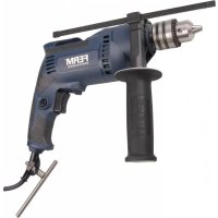
| Product type | Electric impact drill |
| Brand | Ferm |
| Model | PDM1045P |
| Power consumption | 1050 W |
| Supply voltage | 220-230 V~ |
| Mains frequency | 50 Hz |
| No-load speed (speed 1) | 0 - 1 000 min⁻¹ |
| No-load speed (speed 2) | 0 - 2 800 min⁻¹ |
| Impact rate (speed 1) | 0 - 16 000 min⁻¹ |
| Impact rate (speed 2) | 0 - 44 800 min⁻¹ |
| Chuck capacity | 13 mm |
| Weight | 3.2 kg |
| Max. drilling diameter (wood) | 30 mm |
| Max. drilling diameter (concrete) | 20 mm |
| Max. drilling diameter (steel) | 13 mm |
| Sound pressure (L_PA) | 94 + 3 dB(A) |
| Sound power (L_WA) | 105 + 3 dB(A) |
| Vibration (metal drilling) | 2.59 + 1.5 m/s² |
| Vibration (hammer drilling concrete) | 9.00 + 1.5 m/s² |
| Protection class | Double insulation (class II) |
| Functions | Drilling, hammer drilling, variable speed, reversible rotation, switch lock |
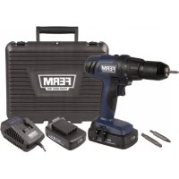
| Included accessories | Side handle, depth stop, chuck key |
| Maintenance | Clean with a soft cloth; carbon brushes replaced by a professional |
| Warranty | Consult the provided warranty certificate |
Frequently Asked Questions - PDM1045P Ferm
User questions about PDM1045P Ferm
0 question about this device. Answer the ones you know or ask your own.
Ask a new question about this device
Download the instructions for your Electric drill in PDF format for free! Find your manual PDM1045P - Ferm and take your electronic device back in hand. On this page are published all the documents necessary for the use of your device. PDM1045P by Ferm.
USER MANUAL PDM1045P Ferm
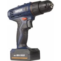
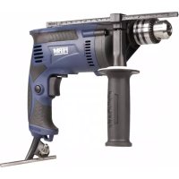
IMPACT DRILL PDM1045P
Thank you for buying this FERM product. By doing so you now have an excellent product, delivered by one of Europe's leading suppliers. All products delivered to you by Ferm are manufactured according to the highest standards of performance and safety. As part of our philosophy we also provide an excellent customer service, backed by our comprehensive warranty. We hope you will enjoy using this product for many years to come.
1.SAFETYWARNINGS

WARNING
Read the enclosed safety warnings, the additional safety warnings and
the instructions. Failure to follow the safety warnings and the instructions may result in electric shock, fire and/or serious injury. Save the safety warnings and the instructions for future reference.
The following symbols are used in the user manual or on the product:

Read the user manual.

Risk of personal injury.

Risk of electric shock.

Immediately remove the mains plug from the mains if the mains cable becomes damaged and during cleaning and maintenance.

Wear safety goggles. Wear hearing protection.

Wear a dust mask.

Double insulated.

Do not dispose of the product in unsuitable containers.

The product is in accordance with the applicable safety standards in the European directives.
ADDITIONAL SAFETY WARNINGS FOR IMPACT DRILLS
Wear ear protectors when impact drilling Exposure to noise can cause hearing loss.
Use auxiliary handle(s), if supplied with the tool. Loss of control can cause personal injury.
Hold power tool by insulated gripping surfaces, when performing an operation where the cutting accessory may contact hidden wiring or its own cord. Cutting accessory contacting a "live" wire may make exposed metal parts of the power tool "live" and could give the operator an electric shock.
Electrical safety
When using electric machines always observe the safety regulations applicable in your country to reduce the risk of fire, electric shock and personal injury. Read the following safety instructions and also the enclosed safety instructions.

Always check that the voltage of the power supply corresponds to the voltage on the rating plate label.

Class II machine - Double insulation - You don't need any earthed plug.
If operating a power tool in a damp location is unavoidable, use a residual current device (RCD) protected supply. Use of an RCD reduces the risk of electric shock.
2. MACHINE INFORMATION
Intended use
Your impact drill has been designed for drilling holes in wood, metal and plastics and for hammer drilling in brick and concrete.
Technical specifications
Mains voltage 220-230 V~
Mains frequency 50Hz
Power input 1050W
No-load speed (1) 0-1,000 /min
No-load speed (2) 0-2,800 /min
Impact rate (1) 0-16,000 / min
Impact rate (2) 0-44,800 /min
Max. chuck size 13 mm
Weight 3.2kg
Max. drill diameter
Wood 30 mm
Concrete 20mm
Steel 13 mm
Noise values
Sound pressure (L_PA)94 + 3dB(A)
Acoustic power (L_WA) 105 + 3dB(A)
Vibration values
Drilling into metal, a_H_2O 2.59 + 1.5 m/s²
Impact drilling into concrete, a_h,10 9.00 + 1.5 m/s²
Vibration level
The vibration emission level stated in this instruction manual has been measured in accordance with a standardised test given in EN 60745; it may be used to compare one tool with another and as a preliminary assessment of exposure to vibration when using the tool for the applications mentioned
- using the tool for different applications, or with different or poorly maintained accessories, may significantly increase the exposure level
- the times when the tool is switched off or when it is running but not actually doing the job, may significantly reduce the exposure level
Protect yourself against the effects of vibration by maintaining the tool and its accessories, keeping your hands warm, and organizing your work patterns.
Description
The numbers in the text refer to the diagrams on page 2.
Fig.A
- Chuck
- Function selection switch
- Depth stop
- Lock-on button
- On/Off switch
- Speed adjustment wheel
- Left/right rotation switch
- Gear selection switch
- Side handle
- Chuck key
3. OPERATING

Impact drills require very little operator pressure. Excessive pressure on the tool can lead to unnecessary overheating of the motor, and burning of the driven tool.
Mounting and removing the auxiliary grip (fig. A) Mounting
- Loosen the auxiliary grip (9).
- Slide the auxiliary grip (9) over the chuck (1).
- Turn the auxiliary grip (9) to the required position.
- Tighten the auxiliary grip (9).
Removing
- Loosen the auxiliary grip (9).
- Remove the auxiliary grip (9) from the chuck (1).
- Tighten the auxiliary grip (9).
Mounting
- Place the chuck key (10) into one of the holes in the chuck (1).
- Open the chuck (1) by turning the chuck key (10) counterclockwise.
- Insert the drill bit (11) into the chuck (1).
- Close the chuck (1) by turning the chuck key (10) clockwise.
- Remove the chuck key (10) from the chuck (1).
Removing
- Place the chuck key (10) into one of the holes in the chuck (1).
- Open the chuck (1) by turning the chuck key (10) counterclockwise.
- Remove the drill bit (11) from the chuck (1).
- Close the chuck (1) by turning the chuck key (10) clockwise.
- Remove the chuck key (10) from the chuck (1).
Setting depth stop
Fig. C
- Insert the depth stop (3) in the hole in the side handle ring.
- Slide the ruler to the desired depth.
The On/Off switch
Fig. A
- Switch the machine on by pressing the On/Off switch (5). When you release the On/Off switch (5) the machine will turn off.
- The rotation-speed can be adjusted by pressing the On/Off switch (5) harder for raising the rotation-speed or release pressure for lowering the rotation-speed.
Lock-on Button
Fig. A
- You can lock the On/Off switch (5) by pressing the On/Off switch (5) and then pressing the lock-on button (4).
- To release the switch-lock; shortly press the On/Off switch (5) again.
Adjusting of the maximum rotation speed
Fig. A
- Adjust the speed by turning the speed adjustment wheel (6) to the desired maximum rotation speed.
Switching the direction of rotation
Fig. A

Do not change the direction of rotation during use.
- Direction of rotation counter-clockwise: shift left/right rotation switch (7) to “.”
- Direction of rotation clockwise: shift left/right rotation switch (7) to “.”
Function selection switch
Fig. A

In order to avoid damage to the machine, adjusting the function selection switch (2) shall only be done when machine is not running
- Set the function selection switch (2) to "..." for drilling.
- Set the function selection switch (2) to "f" for hammer drilling.
Gear selection switch
Fig. A

In order to avoid damage to the machine, adjusting the gear selection switch (8) shall only be done when machine is not running.
- If you set the gear selection switch (8) to position "1", the drilling speed can be adjusted between 0 and 1,000/min.
- If you set the gear selection switch (8) to position "2", the drilling speed can be adjusted between 0 and 2,800/min.
- When the gear selection switch (8) cannot switch easily between "1" and "2", give the chuck (1) a little spin by using your hands. This will help the gears fall into the correct position and makes switching the gears easier.
User tips
Always use the machine with the side handle firmly anchored in place - you will not only work with more comfort, you will also work with more precision.

Caution:drilling bits and hammer drilling bits can get very hot
Drilling and hammer drilling
- For large holes, for instance in very hard concrete, start using a smaller bit for pilot drilling first, then drill to nominal size.
- Hold the machine firmly with 2 hands. Be aware the drill can jam and because of that machine might suddenly turn (Especially when drilling deep holes).
- Do not apply a lot of pressure on the machine, let the machine do the work.
4. MAINTENANCE

Before cleaning and maintenance, always switch off the machine and remove the mains plug from the mains.
Clean the machine casings regularly with a soft cloth, preferably after each use. Make sure that the ventilation openings are free of dust and dirt. Remove very persistent dirt using a soft cloth moistened with soapsuds. Do not use any solvents such as gasoline, alcohol, ammonia, etc. Chemicals such as these will damage the synthetic components.
Carbon brush
If the carbon brushes are worn, the carbon brushes must be replaced by the customer service department of the manufacturer or a similarly qualified person.

Only use the correct original type of carbon brushes.
If the supply cord is damaged, it must be replaced by the manufacturer, its service agent or similarly qualified persons in order to avoid a hazard.
Defects
The machine should be regularly inspected for the following possible defects, and repaired if necessary.
- Damage to power cord
- Broken on/off switch
- Shortcircuting
Damaged moving parts
ENVIRONMENT

Faulty and/or discarded electrical or electronic apparatus have to be collected at the appropriate recycling locations.
Only for EC countries
Do not dispose of power tools into domestic waste. According to the European Guideline 2012/19/EU for Waste Electrical and Electronic Equipment and its implementation into national right, power tools that are no longer usable must be collected separately and disposed of in an environmentally friendly way.
WARRANTY
The warranty conditions can be found on the separately enclosed warranty card.
The product and the user manual are subject to change. Specifications can be changed without further notice.
SCHLAGBOHRMASCHINE PDM1045P
KLOPBOORMACHINE PDM1045P
1. VEILIGHEIDSWAARSCHUWINGEN

WAARSCHUWING
Lees de bijgesloten
Specifications techniques
Perfurarmetal,ah,0 2.59+1.5m/s²
2. INFORMACE O NARADI
Urcenepouziti
Volic prevodovych stapnu Obr. A

Z duvodu zabraneni poskozeni naradi muze byt nastaveni volice prevodovych stapnu (8) provadeno pouze v priade, neni-li naradi v chodu.
Nastavite-li volic prevodovych stapnu (8) do polohy 1^* rozsah otacek pro vrtani bude v Rozmezi od 0 do 1 000/min.
- Nastavite-li volic prevodovych stapnu (8) do polohy 2^4 , rozsah otacek pro vrtani bude v Rozmezi od 0 do 2 800/min.
- Nelze-li volic prévodovych stapnu (8) snadno prépnout mezi polohou „1" a „2", pootocte rukou mirne sklicidlem (1). Tak usnadnite zapadnuti ozubenych kol do spravné polohy a usnadnite provaděni zmeny prévodovych stapnu.
Rady pro uzivatele
BORMASINA CU IMPACT PDM1045P
YDAPHARI PELB PDM1045P
Благорамma npnoobpeTHe npodykTa Ferm. Tepeb y Bac ectb npodukT OTnHOrO KaueCTBa ot Ondoro n3 LyuWnx nocTaBuzNKOB EbpOnbl. Bc npodykua KomnaHn Ferm npo3BOUntcB CooTBeTCTBnC HauBbICwIMn CTaHapTaMn npo3BOUnteJbHOCTn 6e3OpacHOCTn. PoiNTnka Haewe KOMNaHn TaKxe BKIOUcaET npebocxOndoe o6cnyXnbAHne KJIeENTOB n noIHyro rapaHTNo. Mbl haJeemc, YTO 3TOT npodykt npoclyknt Bam mHOrne roDbl.
1. TEXHnKA B3OJNACHOCTN

OCTOPOXHO
mexnuk6e3oacnocmu,doonHumeIbHbIe npedynpexkdeHua o co6liodeHu u mexnuk 6e3oacnochocmu u uHcmpkykuio. HecobJIOJeHne npedynpexKdeHni O co6liOeHN ITexnIK 6e3oacnoCTN u INHCTpyKcM MoKET npNBecT N K nopaxKeHNUO 3JIeKTPnueCKIM TOKOM, NOXapy n/WNI cepBe3HbIM TpaBMam. Coxpanume npedynpexkdeHua o co6liodeHu u mexnuk 6e3oacnochocmu u uHcmpkykuio dnn daNBHeUwe20 ucNoB308aHua.
PnBBeHHe HxKe 3NauchKn nCNoJb3yIOTcB DaHHOM pyKOBoDCTBe Nn Ha npOdyKTe:

Ppoumme pykooeodcmoe noIb306amena.

Puck noJyueHua mpaM.

Onachocmb nopaxeHua 3neKmpueeCKUM mOKOM.

B cnyuae noepexdeHua Ka6eJnumanu, a maKke 60 6peM oUcMku u mexHuuecko2o 6cbNyKuaHua Ka6eJb numanu Heobxodmo omKnIOuymb om po3emku.

IcnoB3yume 3aumHbIe OUK.
IcnoB3yume cpecmBa 3aumbI om
wyma.

IcnoB3yume nbine3aumHyio Macky.

BouHa u30Jua

Bb6pa3b1aume u3dene moIbko 8 npedHa3NaeHHbIe dner 3mo20 KOHmeuHepbl.

JaHoe u3deue coombemcmeyem npumehumbim cmahdapmam 6e3onacHocmu eeponeueckux dupekmue.
TEXHKe 6e3oNaCHOCTn, a TaKke IpnIaRaEmbIe INHCTpyKcIMn NO TEXHKe 6e3oNaCHOCTn.

Y6edumecb e mom, ymo HanpexHue Ucmouhka numaHua coomeemcmyem HanpexHuO, yka3aHHomy ha ma6nUKe c mexHuueckmu daHHbIMu.

I3eue II knacca - BouHa uOJuaB 3a3emHeHou poemke hem Heo6xodumocmu.
Ecnn nCnoNb3OBaHne 3NeKtpOnHCTpyMeHTa B yCNOBnX BnaJxHO NOKpyKaIOUeN Cpebl HEn36exHo, Heo6xoDmO NcNoIb3OBaTb NCTOCHNK TOka, 3aunuehHbYCTPOINCTBOM 3auNTHOr0 OTKnIOueHn (Y3O).PnpmeHHe Ny3O cHnxAet PnCK npaKeHn 3NeKtpnueckm TOKOM.
2. CBDEHNOB 3JIeKTPoHHCTPymHeT E
Ppeonaraemoe nCnoNb3ObaHne
DECLARATION OF CONFORMITY PDM1045P - IMPACT DRILL
(EN) We declare under our sole responsibility that this product is in conformity with directive 2011/65/EU of the European parliament and of the council of 8 June on the restriction of the use of certain hazardous substances in electrical and electronic equipment is in conformity and accordance with the following standards and regulations:
(DE) Der Hersteller erklart eigenverantwortlich, dass diese Produkt der Direktive 2011/65/EU des Europäischen Parlaments und des Rats vom 8. Juni 2011 über die Einschränkung der Anwendung von bestimmten gefährlichen Stoffen in elektrischen und elektronischen Geräten entspricht, den folgenden Standards und Vorschriften entspricht:
(NL) Wij verwlaren onder once volledige verantwoordelijkheid dat dit product voldoet aan de conform Richtlijn 2011/65/EU van het Europees Parlement en de Raad van 8 Juni 2011 betreffende beperking van het gebruik van bepaalde gevaarlijke stoffen in elektrische en elektronische apparatuur en in overeenstem ming is met de volgende standaarden en reguleringen:
(FR) Nous déclarons sous notre seule responsabilité que ce produit est conforme aux standards et directives suivants: est conformé à la Directive 2011/65/EU du Parlement Européen et du Conseil du 8 juin 2011 concernant la limitation d'usage de certaines substances dangereuses dans l'équipment électrique et électronique.
(ES) Declaramos bajo esta exclusiva responsabilidad que este producto cumple con las siguientes nomas y estandares de funcionaimiento; se enquirytra conforme con la Directiva 2011/65/UE del Parliamento Europeo y del Consejo de 8 de junio de 2011 sobre la restricción del uso de determinadas sustancias peligrosas en los equipos electricos y electrónicos.
(PT) Declaramos por esta total responsabilità-de que este produits est em conformidade e cumpe as normas e regulamentações que se seguem: está em conformidade com a Directa 2011/65/EU do Parliamento Europeu e com Conselho de 8 de Junho de 2011 no que respeita à restricão de'utilisation de determinadas substancias perigosas existentes em equipamento eletrico e electrónico.
(II) Dichiariamo, sulla notre responsabilità, che questo prodotto è conforme alle normativè e ai regolamenti segunti: è conforme alla Diretta 2011/65/UE del Parliamente Europeo e del Consiglio dell'8 giugno 2011 sulla limitazione dell'uso di determinate sostanze pericolose nelle appearecchietatie elettriche ed elettroniche.
(SV) Vi garanterarpegetansvatattendaproduktupppylserochfoljerfoljande standarderochbestammelser:upppylderdirektiv2011/65/EUfranEuropeiska parliamentetotEG-radetfenden8junioombegransningenavanvandningav farligasubstandersielektriskohelektroniskutrusting.
(FI) Vakuutamme yksinomaan omalla vastuillamme, etta lamte tayttaa seuraaval standardit ja saadokset: tayyta Euroopan parlementin ja neuvoston 8. kesakuta 2011 päivatyn direktivin 2011/65/EU vaatumkset koskien vaarallisten aineiden käytön rajoitustaa sahko- ja elektronisissa laiteittaee.
(NO) Vi erklaerer und vart eget ansvar at dette prodktet er i samsvar med folgende standarder og regler: er i samsvar med EU-directivet 2011/65/EU fra Europa-parliamentet og Europa-radet, pr. 8 Juni 2011, om begrensning i bruken av visse farlige stoffer i elektrisk og elektronisk ulstyr.
(DA) Vi erklaer under eget ansvar, at dette produkt er i overensstammelse med falgende standarder og bestemmelser: er i overensstammelse med direktiv 2011/65/EU fra Europa-Parliamentet og Rädet af 8. Juni 2011 om begraensingf anvendelsen af visse farlige stoffer ie elektrisk og elektronisk udystr.
(HU) Felelossegugn teljes tudataban kijelentjuk, hogy ez a termek teljes mertkben megfeel az alabbi szabvanyoknak es eliorasoknak: je v souladu se smernici 2011/65/EU Evropskeho parlamentu a Rady EU ze dne 8. cervna 2011, ktera se tykane omezeni pouziti urcitych nebezpecnych latek v elektrickych a elektronickych zaifienich.
(CZ) Na naši vlastni zodpovednost prohlasujeme,Že je tento vyrobek v souladu s nasludujcim standarda u normami: Je v sulade s normou 2011/65/EU Europskeho parliamentu a Rady z 8. Juna 2011 týkajucej sa obmedzenia použivania určitych nebezepechnych látok v elektrikkom a elektronikkom vybaveni.
(SK) Vyhelasujeme nana suVyhradnú zodpovednost, ze tento vyrobokje v zhode a sulade s nasledujuciimi normami a predisipmi: Je v sulade s normou 2011/65/EU Europske ho parlementu a Rady 8. juna 2011 tykajucej sa obmedzenia pouzivania urcitych nebezepečnýt lasko v elektrikkom a elektronikkom vybaveni.
(SL) S polno odgovomostjo izjavlamo, daje t izdelek v skladu in da odgovarja nasledn-jim standardom terpredpisom: je v skladu z direktivo 2011/65/EU Evropsega parla-menta in Sveta z dne 8. juni 2011 o omejevanju uporabe dolocenih nevamih snovi v elektrici n in elektronski upremi.
(PL) Deklarujemy na wlasn odpwiedzialnosc, ze ten produkt spelnilia wymogizawarte w nastepuiacych nomach i przypesachat: jest zgodny z Dyrektwyq 2011/65/UE Paria mentu Europejskiego i Rady z dnia 8 czerwca 2011 r. w sprawie ograniczenia stosowania niedtorychie niebepezcznych substancji w sprzecie elektrycznym i elektronicznym.
(LT) Prisiimdami visa atsakomybe deklaruojame, kad sis gaminyi atlinka zemiau paminétus standartus arba nuostatus: atlinka 2011 m. birzeli 8 d. Europos Parliamento ir Tarybos direktlyva 2011/65/EB del tam tikru pavojingu medziagu naudojimo elektros ir elektronineje irangoje apribojo.
(LV) Ir albstósa Eiropas Parliamenta un Padomes 2011. gada 8. jünja Direktivá 2011/65/ES par dazu bistamu vielu izmantoşanas ierobezoşanu elektriskás un elektroniskás ekjárás.
(ET) Apgalvojam ar visu atbildibu, ka isis produits ir saskaanà un abilst sekojsiem standartiem un nolikumemi: ir abilstosa Eiropas Parimenta un Padomes 2011, gada 8, junja Direktivai 2011/65/ES par dazu blistamu vielu izmantoşanas ierobežosanu elektriskas un elektroniskas iekartás.
(RO) Declaram prin aceasta cun raspunderea deplina cà produsul acesta este in conformitate cu urmatoarele standarde sau directive: este in conformitate cu Direcva 2011/65/UE a Parliamentului Europeano si a Consiliulii din 8 unie 2011 cu privire la interzicerea utilizari anumitor substanje periculoase la echipamente tele electrice si electronice.
(HR) Izjavljemo pod vlasitom odgovornu, su da je strojem ukladan sa slijeedesim standardima ill standardiziranim dokumentima i u skladu sa odredbama: uskladeno s Direktivom 2011/65/EU europskog parliamenta i vije za izdanom 8. lipna 2011. oograficenju koristjenva odreedeni opasnih vari u elektrnej 1 elektronickoj opremi.
(SRL)Pod punom odgovomoscu izjavljume doaje usaglasen sa sledecim standardima lii normama: usaglasen sa direktivom 2011/65/EU Evropskog parlamenta i Saveta od 8.juna.2011. godine za restrkciju upotrebe odredenih opasnih materija u elektricnoj i elektronskoj opremi.
(RU) NIO CBOIO OTBeTcBHeHOCb 3aABnBREM, YTO DaHHoe H3dene COOTBeTcBTByeC nIeDyouIMM CTanapTAM HOPMAM: COOTBeTcBTye Tpe6OBAHNIM DneKTIbbl 2011/65/EU EBponeckoro napnameHTa coBETA OT 8 MOHA 2011 r. no ORpaHNeHHIO MIONBoTBAHOHOnpeDeNEHbIX OnaChbIX BeueCTB a3NEKTPmckOM mNEKTPHOHOM 06OpDyOBAHIM
(UK) Ha cboo BnacHy bIIOBnIaIbIcIbIcIbIcIbIcIbIcIbIcIbIcIbIcIbIcIbIcIbIcIbIcIbIcIbIcIbIcIbIcIbIcIbIcIbIcIbIcIbIcIbIcIbIcIbIcIbIcIbIbcN 100000000000000000000000000000000000000000000000000000000000000000000000000000000000
(EL) Anivoume uteubvOn to Tpoiv autuupwwei KaTpeTc napakTu Kavoviaouc Ka TpOtu: uuaopagveTae mTv OyNia 2011/65/EE tou Eupmaikou KoVbouloukou Tou SuOpouLIOu Tn Btiovuiou 2011 vao Tepioipiao nTx pohont opaevuv Etnikovuv ouoiue ae Nekiptko Ka Nekiptovka eGonAq
(AR) 10000000000000000000000000000000000000000000
(TR) Tek sorumlusu bize olarak bu irinun agidaki standart ve yongelere uygun oldugu n buenan edizeri.
EN55014-1, EN55014-2, EN60745-1, EN60745-2-1, EN61000-3-2, EN61000-3-3
2006/42/EC, 2014/30/EU, 2011/65/EU, 2012/19/EU
Zwolle, 01-04-2018 H.G.F. Rosberg
CEO Ferm B.V.
Ferm BV · Lingenstraße 6 · 8028 PM · Zwolle The Netherlands
- IMPACT DRILL PDM1045P
- 1.SAFETYWARNINGS
- WARNING
- ADDITIONAL SAFETY WARNINGS FOR IMPACT DRILLS
- Electrical safety
- MACHINE INFORMATION
- Intended use
- Technical specifications
- Max. drill diameter
- Noise values
- Vibration values
- Vibration level
- Description
- Fig.A
- OPERATING
- Mounting and removing the auxiliary grip (fig. A) Mounting
- Removing
- Mounting
- Setting depth stop
- Fig. C
- The On/Off switch
- Fig. A
- Lock-on Button
- Adjusting of the maximum rotation speed
- Switching the direction of rotation
- Function selection switch
- Gear selection switch
- User tips
- Drilling and hammer drilling
- MAINTENANCE
- Carbon brush
- Defects
- ENVIRONMENT
- Only for EC countries
- WARRANTY
- SCHLAGBOHRMASCHINE PDM1045P
- KLOPBOORMACHINE PDM1045P
- VEILIGHEIDSWAARSCHUWINGEN
- WAARSCHUWING
- Specifications techniques
- INFORMACE O NARADI
- Urcenepouziti
- Volic prevodovych stapnu Obr. A
- Rady pro uzivatele
- BORMASINA CU IMPACT PDM1045P
- YDAPHARI PELB PDM1045P
- TEXHnKA B3OJNACHOCTN
- OCTOPOXHO
- CBDEHNOB 3JIeKTPoHHCTPymHeT E
- Ppeonaraemoe nCnoNb3ObaHne
- DECLARATION OF CONFORMITY PDM1045P - IMPACT DRILL
Brand : Ferm
Model : PDM1045P
Category : Electric drill