L 3709115 - Grinder Flex - Free user manual and instructions
Find the device manual for free L 3709115 Flex in PDF.
Frequently Asked Questions - L 3709115 Flex
User questions about L 3709115 Flex
0 question about this device. Answer the ones you know or ask your own.
Ask a new question about this device
Download the instructions for your Grinder in PDF format for free! Find your manual L 3709115 - Flex and take your electronic device back in hand. On this page are published all the documents necessary for the use of your device. L 3709115 by Flex.
USER MANUAL L 3709115 Flex
Symbols used in this manual 14
Symbols on the power tool. 14
For your safety 14
Noise and vibration 17
Technical specifications 18
Overview 19
Operating instructions 20
Maintenance and care 22
Disposal information 23
-Declaration of Conformity 23
Exemption from liability 23
Symbols used in this manual

WARNING!
Denotes impending danger.
Non-observance of this warning may result in death or extremely severe injuries.

CAUTION!
Denotes a possibly dangerous situation.
Non-observance of this warning may result in slight injury or damage to property.

NOTE
Denotes application tips and important information.
Symbols on the power tool

Before switching on the power tool, read the operating manual!
Wear goggles!

Protection class II (completely insulated)
Disposal information for the old machine (see page 23)!
For your safety

WARNING!
Before using the angle grinder, please read and follow:
- these operating instructions,
the "General safety instructions" on the handling of power tools in the enclosed booklet (leaflet-no.: 315.915), - the currently valid site rules and the regulations for the prevention of accidents.
This angle grinder is state of the art and has been constructed in accordance with the acknowledged safety regulations.
Nevertheless, when in use, the power tool may be a danger to life and limb of the user or a third party, or the power tool or other property may be damaged. The angle grinder may be operated only if it is
as intended,
in perfect working order.
Faults which impair safety must be repaired immediately.
Intended use
This angle grinder
- for commercial use in industry and trade,
- is designed for dry grinding and cutting metal and stone,
- a special cutting guard is required for cutting,
- is designed for use with grinding tools and accessories which are indicated in this manual or recommended by the manufacturer and which are permitted to run at a circumferential speed of 80~m / s .
Not permitted are e.g. chain cutting wheels, saw blades.
Safety instructions

WARNING!
Read all safety warnings, instructions, illustrations and specifications provided with this power tool. Failure to follow all instructions listed below may result in electric shock, fire and/or serious injury. Save all warnings and instructions for future reference.
SafetyWarnings Common for Grinding or Abrasive Cutting-Off Operations
This power tool is intended to function as a grinder or cut-off tool. Read all safety warnings, instructions, illustrations and specifications provided with this power tool. Failure to follow all instructions listed below may result in electric shock, fire and/or serious injury.
- Operations such as sanding, wire brushing or polishing are not recommended to be performed with this power tool. Operations for which the power tool was not designed may create a hazard and cause personal injury.
- Do not use accessories which are not specifically designed and recommended by the tool manufacturer. Just because the accessory can be attached to your power tool, it does not assure safe operation.
The rated speed of the accessory must be at least equal to the maximum speed marked on the power tool. Accessories running faster than their rated speed can break and fly apart.
- The outside diameter and the thickness of your accessory must be within the capacity rating of your power tool. Incorrectly sized accessories cannot be adequately guarded or controlled.
- Threaded mounting of accessories must match the grinder spindle thread. For accessories mounted by flanges, the arbour hole of the accessory must fit the locating diameter of the flange.
- Accessories that do not match the mounting hardware of the power tool will run out of balance, vibrate excessively and may cause loss of control.
- Do not use a damaged accessory. Before each use inspect the accessory such as abrasive wheels for chips and cracks, backing pad for cracks, tear or excess wear, wire brush for loose or cracked wires. If power tool or accessory is dropped, inspect for damage or install an undamaged accessory. After inspecting and installing an accessory, position yourself and bystanders away from the
plane of the rotating accessory and run the power tool at maximum no-load speed for one minute. Damaged accessories will normally break apart during this test time.
- Wear personal protective equipment. Depending on application, use face shield, safety goggles or safety glasses. As appropriate, wear dust mask, hearing protectors, gloves and workshop apron capable of stopping small abrasive or workpiece fragments. The eye protection must be capable of stopping flying debris generated by various operations. The dust mask or respirator must be capable of filtrating particles generated by your operation. Prolonged exposure to high intensity noise may cause hearing loss.
- Keep bystanders a safe distance away from work area. Anyone entering the work area must wear personal protective equipment. Fragments of workpiece or of a broken accessory may fly away and cause injury beyond immediate area of operation.
- Hold the power tool by insulated gripping surfaces only, when performing an operation where the cutting accessory may contact hidden wiring or its own cord. Cutting accessory contacting a "live" wire may make exposed metal parts of the power tool "live" and could give the operator an electric shock.
Position the cord clear of the spinning accessory. If you lose control, the cord may be cut or snagged and your hand or arm may be pulled into the spinning accessory. - Never lay the power tool down until the accessory has come to a complete stop. The spinning accessory may grab the surface and pull the power tool out of your control.
- Do not run the power tool while carrying it at your side. Accidental contact with the spinning accessory could snag your clothing, pulling the accessory into your body.
-
Regularly clean the power tool's air vents. The motor's fan will draw the dust inside the housing and excessive accumulation of powdered metal may cause electrical hazards.
-
Do not operate the power tool near flammable materials. Sparks could ignite these materials.
- Do not use accessories that require liquid coolants. Using water or other liquid coolants may result in electrocution or shock.
Kickback and RelatedWarnings
Kickback is a sudden reaction to a pinched or snagged rotating wheel, backing pad, brush or any other accessory. Pinching or snagging causes rapid stalling of the rotating accessory which in turn causes the uncontrolled power tool to be forced in the direction opposite of the accessory's rotation at the point of the binding. For example, if an abrasive wheel is snagged or pinched by the workpiece, the edge of the wheel that is entering into the pinch point can dig into the surface of the material causing the wheel to climb out or kick out. The wheel may either jump toward or away from the operator, depending on direction of the wheel's movement at the point of pinching. Abrasive wheels may also break under these conditions. Kickback is the result of power tool misuse and/or incorrect operating procedures or conditions and can be avoided by taking proper precautions as given below.
- Maintain a firm grip on the power tool and position your body and arm to allow you to resist kickback forces. Always use auxiliary handle, if provided, for maximum control over kickback or torque reaction during start-up. The operator can control torque reactions or kickback forces, if proper precautions are taken.
- Never place your hand near the rotating accessory. Accessory may kickback over your hand.
-
Do not position your body in the area where power tool will move if kickback occurs. Kickback will propel the tool in direction opposite to the wheel's movement at the point of snagging.
Use special care when working corners, sharp edges etc. Avoid bouncing and snagging the accessory. Corners, sharp edges or bouncing have a tendency to snag the rotating accessory and cause loss of control or kickback. -
Do not attach a saw chain woodcarving blade or toothed saw blade. Such blades create frequent kickback and loss of control.
SafetyWarnings Specific for Grinding and Abrasive Cutting-Off Operations
- Use only wheel types that are recommended for your power tool and the specific guard designed for the selected wheel. Wheels for which the power tool was not designed cannot be adequately guarded and are unsafe.
- The grinding surface of centre depressed wheels must be mounted below the plane of the guard lip. An improperly mounted wheel that projects through the plane of the guard lip cannot be adequately protected.
The guard must be securely attached to the power tool and positioned for maximum safety, so the least amount of wheel is exposed towards the operator. The guard helps to protect the operator from broken wheel fragments, accidental contact with wheel and sparks that could ignite clothing. - Wheels must be used only for recommended applications. For example: do not grind with the side of cut-off wheel. Abrasive cut-off wheels are intended for peripheral grinding; side forces applied to these wheels may cause them to shatter.
Always use undamaged wheel flanges that are of correct size and shape for your selected wheel. Proper wheel flanges support the wheel thus reducing the possibility of wheel breakage. Flanges for cut-off wheels may be different from grinding wheel flanges. - Do not use worn down wheels from larger power tools. Wheel intended for larger power tool is not suitable for the higher speed of a smaller tool and may burst.
Additional SafetyWarnings specific for Abrasive Cutting-Off Operations
- Do not "jam" the cut-off wheel or apply excessive pressure. Do not attempt to make an excessive depth of cut. Overstressing the wheel increases the loading and susceptibility to twisting or binding of the wheel in the cut and the possibility of kickback or wheel breakage.
- Do not position your body in line with and behind the rotating wheel. When the wheel, at the point of operation, is moving away from your body, the possible kickback may propel the spinning wheel and the power tool directly at you.
- When wheel is binding or when interrupting a cut for any reason, switch off the power tool and hold the power tool motionless until the wheel comes to a complete stop. Never attempt to remove the cut-off wheel from the cut while the wheel is in motion otherwise kickback may occur. Investigate and take corrective action to eliminate the cause of wheel binding.
- Do not restart the cutting operation in the workpiece. Let the wheel reach full speed and carefully re-enter the cut. The wheel may bind, walk up or kickback if the power tool is restarted in the workpiece.
Support panels or any oversized workpiece to minimize the risk of wheel pinching and kickback. Large workpieces tend to sag under their own weight. Supports must be placed under the workpiece near the line of cut and near the edge of the workpiece on both sides of the wheel.
Use extra caution when making a "pocket cut" into existing walls or other blind areas. The protruding wheel may cut gas or water pipes, electrical wiring or objects that can cause kickback.
Additional safety instructions
The mains voltage and the voltage specifications on the rating plate must correspond.
- Do not press the spindle lock until the grinding tool stops.
Noise and vibration

NOTE
Values for the A-weighted sound pressure level and for the total vibration values can be found in the "Technical specifications" table.
The noise and vibration values have been determined in accordance with EN 60745.

CAUTION!
The indicated measurements refer to new power tools. Daily use causes the noise and vibration values to change.

NOTE
The vibration emission level given in this information sheet has been measured in accordance with a standardised test given in EN 60745 and may be used to compare one tool with another. It may be used for a preliminary assessment of exposure. The declared vibration emission level represents the main applications of the tool. However if the tool is used for different applications, with different accessories or poorly maintained, the vibration emission may differ. This may significantly increase the exposure level over the total working period. However if the tool is used for different applications, with different accessories or poorly maintained, the vibration emission may differ. This may significantly decrease the exposure level over the total working period.
Identify additional safety measures to protect the operator from the effects of vibration such as: maintain the tool and the accessories, keep the hands warm, organisation of work patterns.

CAUTION!
Wear ear protection at a sound pressure above 85 dB(A).
Technical specifications
| L 3709-115 | L 3709 -125 L 801 | LE 9-10 125 | L 10 -10 125 L 1001 | ||
| Machine type | Angle grinder | ||||
| Max. grinding tool Ø | mm 115 | 125 125 125 | |||
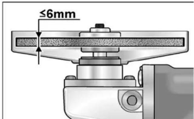
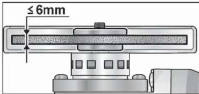
| Grinding tool thickness | mm 1-6 | ||||
| Tool hole diameter | mm 22 | 23 | |||
| Spindle thread | M14/WAF14 | ||||
| Speed | r.p.m. | 2500 | 12000 | 6000-11500 | 10000 |
| Power input | W | 750 (650*) | 800 900 | 1010 | |
| Power output | W | 450 (400*) | 480 530 | 600 | |
| Weight according to “EPTA Procedure 01/2003” (without power cord) | kg 1,9 | 2,0 2,2 | |||
| Protection class | II/□ | ||||
| A-weighted sound pressure level according to EN 60745 (see “Noise and vibration"): | |||||
| Sound pressure level LpA | dB(A) | 84.6 87 91 | |||
| Sound power level LWA | dB(A) | 95.6 98 102 | |||
| Uncertainty K | db | 3 | |||
| Total vibration value according to EN 60745 (see “Noise and vibration"): | |||||
| Emission value ah when grinding surfaces | m/s2 | 6.5 6.5 6.6 | |||
| Emission value ah when cutting-off | m/s2 | 6.3 8.1 6.2 | |||
| Uncertainty K | m/s2 | 1.5 | |||
(^*) = 110V
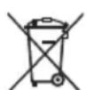
Overview
1 Spindle
2 Threaded flange
a Clamping nut
b Clamping flange
3 G u a r d
4 Handle
Handle can be fitted to the left or right.
5 Spindle lock
Secures the spindle when the tool is changed.
6 Gear head
With air outlet and direction-of-rotation arrow.
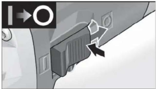
7 Switch rocker
Switches the power tool on and off. With notched position for continuous operation.
8 4.0 m power cord with plug
9 Face spanner
10 Rating plate (not illustrated)
11 Dial for preselecting the speed (only LE 9-10 125)
Operating instructions

WARNING!
Before carrying out any work on the angle grinder, always pull out the mains plug.
Before switching on the power tool Unpack the angle grinder and check that there are no missing or damaged parts.
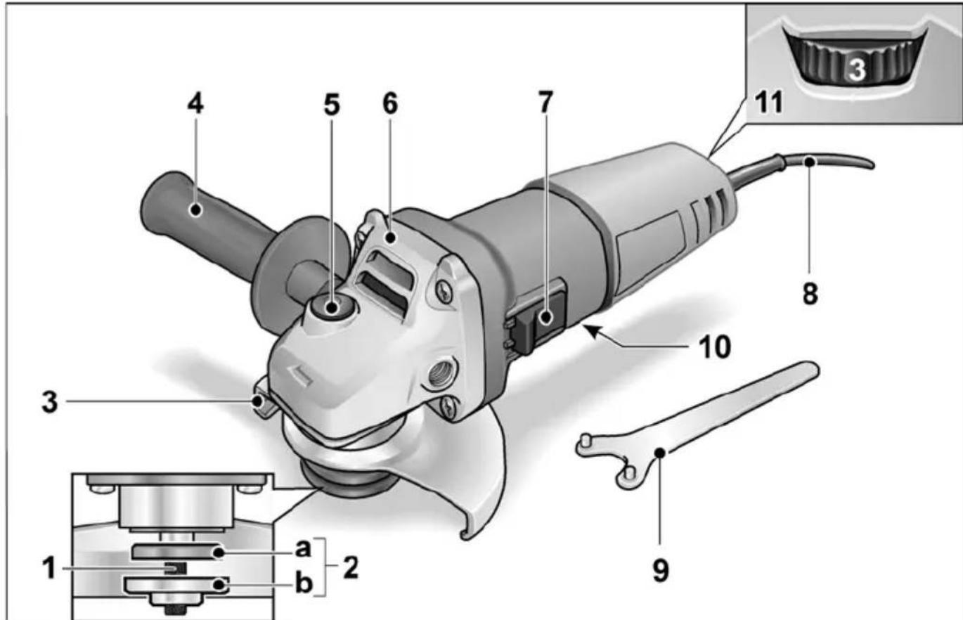
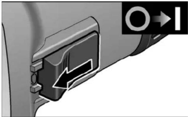
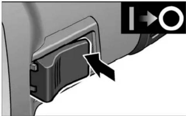
Switching on and off Brief operation without engaged switch rocker:
- Push the switch rocker forwards and hold in position.
To switch off the power tool, release the switch rocker.
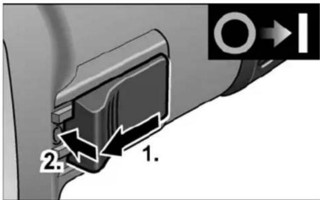
Continuous operation with engaged switch rocker:

Push the switch rocker forwards (1.) and engage by pressing the front end (2.).
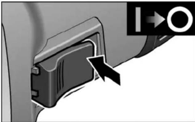
To switch off the power tool, release the switch rocker by pressing the rear end.
i NOTE
Following a power failure, the switched on power tool does not restart.
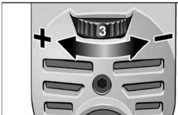
Speed preselection (LE 9-10 125 only)
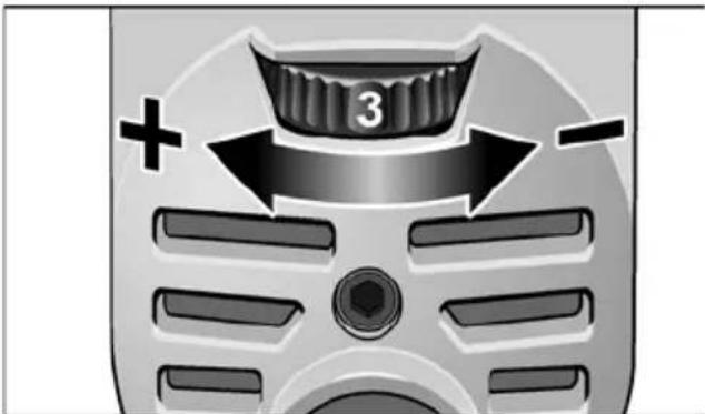
To set the operating speed, move the dial to the required value.
Safety guard
(L 3709-115, L 801, L 3709-125)
WARNING!
Never work without the safety guard.
The angle grinder is adapted to the job with the safety guard which can be adjusted without a tool.
A special cutting guard must be used for cutting.
CAUTION!
Risk of injury! Wear protective gloves.
Pull out the mains plug.
- Rotate safety guard to the required position.
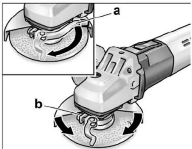
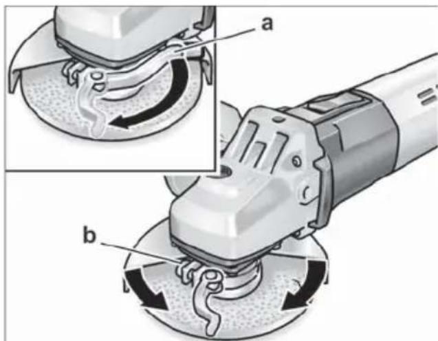
Quick-release guard (LE 9-10 125, L 10-10 125, L 1001)

WARNING!
When using the angle grinder for roughing or cutting, never work without the guard.
Pull out the mains plug.
Loosen the clamping lever (a).
Adjust the guard.
- Tighten screw (b) until the clamping lever can just be clamped by hand.
Retighten the clamping lever.
A special quick-release cutting guard must be used for cutting.
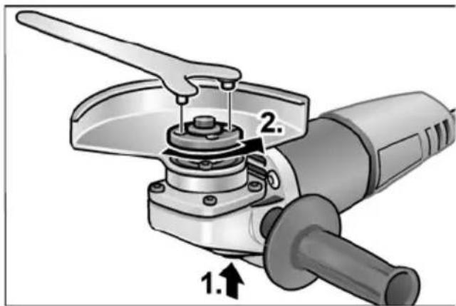
Attaching or changing the grinding tool
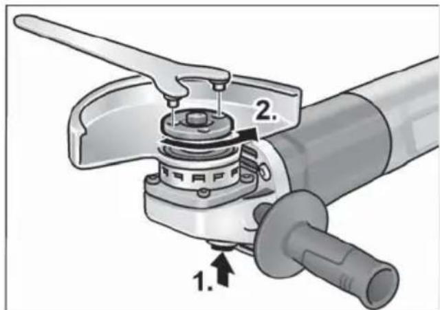
Pull out the mains plug.
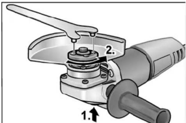
Press and hold down the spindle lock (1.).
Using the face spanner, loosen the clamping nut on the spindle in an anticlockwise direction and remove (2.).
Insert the grinding wheel in the correct position.
Screw the clamping nut with flange face up, onto the spindle.
Press and hold down the spindle lock.
- Tighten the clamping nut with the face spanner.
Insert the mains plug into the socket.
- Switch on the angle grinder (without locking into position) and leave the angle grinder running for approx. 30 seconds. Check for imbalances and vibrations.
- Switch off the angle grinder.
Operating instructions
i NOTE
When the power tool is switched off, the grinding tool continues running briefly.
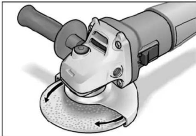
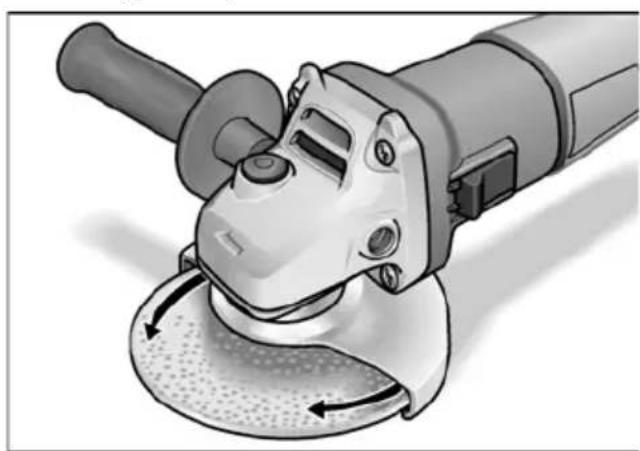
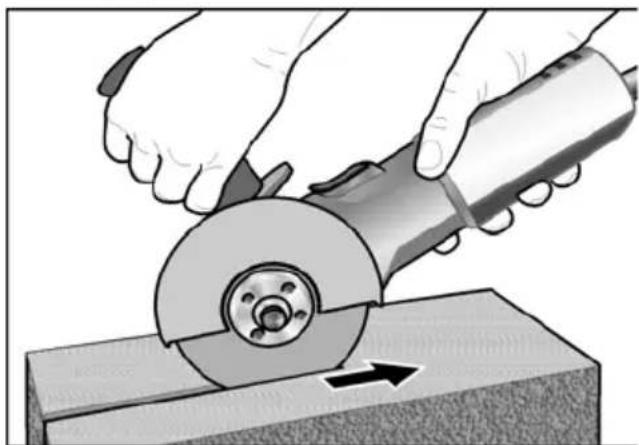
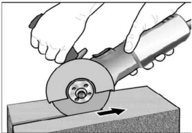
Rough-grinding
WARNING!
Never use cutting-off wheels for rough grinding.
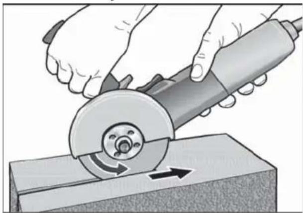
- Angle of wheel 20 - 40^ for best cutting performance.
- Applying moderate pressure, move the angle grinder backwards and forwards. As a result, the workpiece will not become too hot and there will be no discoloration; nor will there be any grooves.
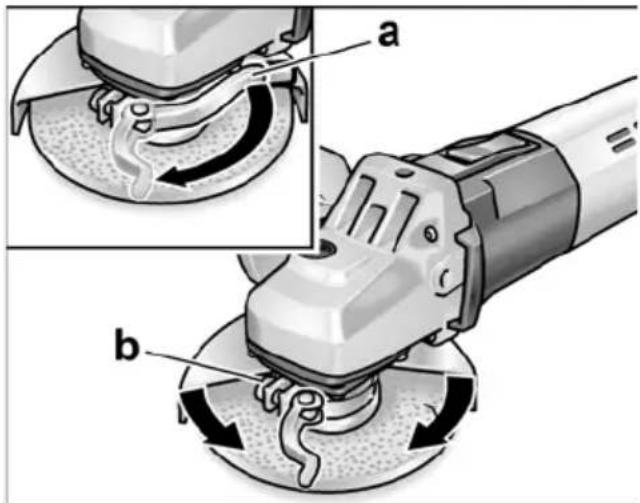
Cut-off grinding
WARNING!
A special cutting guard must be used for cut-off grinding.
- Do not press, tilt or oscillate the power tool.

Angle grinder must always operate in the counter direction. Otherwise, there is a risk of the angle grinder jumping uncontrollably out of the groove.
- Adjust the feed to the material which is to be work: the harder the material, the slower the feed.
For further information on the manufacturer's products go to www.flex-tools.com.
Maintenance and care
WARNING!
Before carrying out any work on the angle grinder, always pull out the mains plug.
Cleaning
WARNING!
If metals are ground or cut over a prolonged period, conductive dust may become deposited inside the housing. Impairment of the protective insulation! Operate the power tool via a residual-current-operated circuit-breaker (stripping current 30 mA).
Regularly clean the power tool and ventilation slots. Frequency of cleaning is dependent on the material and duration of use.
Regularly blow out the housing interior and motor with dry compressed air.
Carbon brushes
The angle grinder features cut-off carbon brushes.
When the wear limit of the cut-off carbon brushes is reached, the angle grinder switches off automatically.
i NOTE
Use only original parts supplied by the manu-facturer for replacement purposes. If non-original parts are used, the guarantee obligations of the manufacturer will be deemed null and void.
When the power tool is being used, the carbon brushes can be seen sparking through the rear air inlet apertures.
If the carbon brushes spark excessively, switch off the angle grinder immediately. Take the angle grinder to a customer service workshop authorised by the manufacturer.
Gears
i NOTE
Do not loosen the screws on the gear head during the warranty period.
Non-compliance will deem the guarantee obligations of the manufacturer null and void.
Repairs
Repairs may be carried out by an authorised customer service centre only.
Spare parts and accessories
Other accessories, in particular sanding tools and cutting guards, can be found in the manufacturer's catalogues.
Exploded drawings and spare-part lists can be found on our homepage: www.flex-tools.com
Disposal information

WARNING!
Render redundant power tools unusable by removing the power cord.

EU countries only
Do not throw electric power tools into the household waste!
In accordance with the European Directive 2012/19/EU on Waste Electrical and Electronic Equipment and transposition into national law used electric power tools must be collected separately and recycled in an environmentally friendly manner.

NOTE
Please ask your dealer about disposal options!
-Declaration of Conformity
We declare under our sole responsibility that the product described under "Technical specifications" conforms to the following standards or normative documents:
EN 60745 in accordance with the regulations of the directives 2014/30/EU, 2006/42/EC, 2011/65/EU.
Responsible for technical documents:
FLEX-Elektrowerkzeuge GmbH, R & D
Bahnhofstrasse 15, D-71711 Steinheim/Murr


Eckhard Rihle
Manager Research &
Development (R & D)
Klaus Peter Weinper
Head of Quality
Department (QD)
Exemption from liability
The manufacturer and his representative are not liable for any damage and lost profit due to interruption in business caused by the product or by an unusable product.
The manufacturer and his representative are not liable for any damage which was caused by improper use of the power tool or by use of the power tool with products from other manufacturers.
Table des matieres
Manager Research & Development (R & D)
Klaus Peter Weinper
Head of Quality Department (QD)
Manager Research & Development (R & D)
Klaus Peter Weinper
Head of Quality
Department (QD)
Koivc TpoeiOoiTikc aTodEiEic yia iavon kai yia epyaiec kottns
To npov nEeKtpiK opyaeeio EITIeTTA va xpnaiottoieitai wC aeiavtnpac kai unxavma aeiavongkottnc. Tnpite oec tic utodoeic aoppaiaac kai obnyiec kai TpoaeTc Ypawikec Tapaotaceic kai ta edoeva, ta otioa aapabvete μe to unxavma. Av dev npnoTe Tc akOauoec odnyiec mtopei va oupei nEeKtpoTAnxi, Tupkayia kai/ npapi Taupaata.
To npov nEeKpiKO epyaaleio 8ev evai katalnnlo ia aeavon eumupidoxapto, epyaoies eoupatoBouptoe c kai otlaow. Xpnoic, yia tioe 8ev pooipctai to nEeKpiKO uxavma, mTpei va Tpokaleouv Kivduvouc kai Tpaumatouc.
Mn xpnoiopoioitepiote eapntmuata, ta oioia dev exouv npo3eephei ato tovkataaekuaotni EIDika y' auto To nEKTPIKO unxavma. Movov etieon mTOpEITE va otepewoetra eapntmuata oTo nEKTPIKO unxavnaocac, auto dev mTOpEVAeyunthei Tny aoqpaan xpnon.
O eTIPeTToC apiOc oTPOwV tou
epyaleiou epapoyns TpTeI va eivai
toulambdaioTov too eYaloc, otWs
o eviatoC apiOc oTPOwV tou
avaypaetai oTo nEKTPIKO uXavnua.
Eaaptna, ta oToia TEPIOPTeovTai
taxeP aTT OTI eTTpeTTeai, mTopei
va ataouv kai va EKQevDovIOuV
TPOc oAEC TIC KATEUUVSeIc.
H diaeptoq kai to Tpaxoc Tou epyaaleiou epapouyns TpETeI vaavatokpivovtai ota stoixia TIC diaotacoei tou nAektpikou mXavnauToC aC.
Epyaia eapauync me avthetaevcs diaotaaic dev tuyxavouv enapkous npoataiaoc oute mtopoov va eeyxooiv.
Epyaεia με βiδωτη ΑUTOOxyπpεπει va taipiaζouv ακρiβως στο σπεipωμa tou áξova. Στα εpyaεia Tou ou vapμoλoyouvtauι με τη βοήθεia φλavτας πρεπει n δίαμετρος tnc τριτας Tou εpyaεiouva taipiaζει στη δίαμετρο tnc uTOOxyns TNC φλavτας. Ta εpyaεia εφapμoγης, ta ΑΟΙΑ δεν taipiaζουv ακρiβως στην ἀτρακτο λείανας Tou nλεκτρικού μηχανηματος, προξενουν πολι σιχυρούς κραδασμούς και μπθούνν a Oδηŋσουν στην αΤιώλεια Tou ελέyyou.
Mn xpnoiotoinoTe kateopapueva
epyaia eapuoyns. Na eayxete
Tavote ta epyaia Tou poketai va
xpnoiotoinoTe, T.X. Touc biakouc
KOTnc yia otaijata kai pwyeç, Tou
diakouc leiavons yia pwyeç, othetac
n Eeptiaata kai ticoupatobouptae
yia xaapa n otaaeva oupuata. Av to
nEktpiKO unxavma n To epyaaleio
eapuoync Teouv katw, eEyxte Ta
yia cniiec n xpnoiotoinote eva aTheta
epyaiao eapuoync. ApoU eleyxthke kai
avtikataotaanke TO epyaaleio eapuoync,
attoupakpvthe TEeic kai aalaa TPO
omega toun BiipkovtaikovTa OTO mynxavna
mu atto ETTIO TO TEPIOTpepoevou
epyaiaou eapuoync kai ektealeote ia
bokimaotikn aeitoupyia Tou mynavnatoc
diapkeiaeEvoc LEITOU ME TO Meyioto
apioo OTPOWv.
Ta kateotpaumveA epyaia eapuoync
otnacouv otic TEPIOOTePEC TEPiTTwoeic
EVTOC autou tou xpovou bokimng.
ΦopATE TPOOWTIKO TPOOTATEUTIKO oTIAIO. XpnoIpoTOIEe avaoya TIV EFAPUoyn TAnpn TPOOtaia TPOoWtou, TPOOtaia paIwv n TPO- OTeUTiKa maToyuAIA.
OTAV xpeiaZeta, foape taoka TPOOtaiaac aTIO kovn, wtoaotidec, TPOOATAeutikayavTIA n EIDIKn TODia, n OTIOA Kpata paakpa oac ta iikpa Owpatidia Aiavtikou kai uIKwv.
Ta maia a πeTTIva TTPOoTATEuovTAI aTIO Owata Tou EKoqevDoviOvTAI TPOc oAEC TIG KATEUooiC kai TPOkUTTOV OE diapoeε εφapoyεc.
H PpOoTaia aTn oKovn n n MaKa TpOaiaac avantvoN TpETeI va qIATpApouv Tnv OKovn Tou OxmuatZetai kata Tnv εφapoyn. Av iotE EKTeθεiμévoi yia μeyalo diaσtnμa σε duvaro θópuβo, μTOpεite v aattwλεσεTe Tny akon σac.
PpOeXETe va pioKovTai Ta aAa Tpo- OwTn oE aTcTaon aQpaAiaC aTo Tnv TepioxN epyaiaC aC.
Klaus Peter Weinper
Head of Quality
Department (QD)
Klaus Peter Weinper
Head of Quality
Department (QD)
Klaus Peter Weinper
Head of Quality
Department (QD)
Hrup in tresljajin 196
Navodila za uporabo 199
EN 60745 conform preoderilor Directivei 2014/30/UE, 2006/42/CE, 2011/65/UE.
Responsabili pentru documento tehnice: FLEX-Elektrowerkzeuge GmbH, R & D Bahnhofstrasse 15, D-71711 Steinheim/Murr


Eckhard Röhle
Manager Research & Development (R & D)
Klaus Peter Weinper
Head of Quality
Department (QD)
HaTnCKaIte 6IOKIpOBKaTa Ha BpeTeHOTO CAMO KOraTO INHCTpyMeHTbTe E BnOKoJ.
Uymn Bn6paun

YKA3AHHE!
CTOHOCHTe 3a A-npeterHOTo HUBO Ha
WyMa, KaKTo N O6uHTe CTOHOCTu 3a
Bb6paunTe MoKeTe Da HamePnte
B Tabnucata "TexHueckn daHHN".
CTOHOCHTe 3a Wym N Bb6paun ca
ONpeJeHeHn B cbOTBeTcTBne c EN 60745.

BHIMMAHVE!
IocoueHnte CToHOCHTBaxaT 3a HOBVypeu. Ipn n3nON3BaHe B exEJHEBNEOTCToHOCHTte Ha Wym N Bu6paun Ce npomeHr.

YKA3AHHE!
ДадeНоTOВTOBAуNTBaHe HNBOHa Bn6paци e N3MepeHO B cBoTBeTCTBne c onpeTeJIeHata B EN 60745 npoZeIpya NO N3MepBaHe n MOxke Da ce N3NoI3Ba 3a CpaBnBaHe Ha eNeKtpUeCKn INHCTpyMeHT. To e NODxoJIo o 3a npedBapuTeJHa npeUeHka Ha Bn6paZInTe.
IocOeHOTo HNBO Ha Bn6paZm npeIcTaBra OCHOBnITE npINOxKeHnHa eNeKtpUeCKn INHCTpymENT. Korato obaue neKtpn-yeCKnRT INHCTpymENT Ce N3NoI3Ba 3a dpyrUeJI, C HeNoDxOJaI npICTaBKn IIN HEnPaBnIO HO6CnykBaHe, HNBOTo Ha Bn6paZm MoXe Da e pa3NHyO.
Toba moXe 3NaHTeJHo Da NOBUnBn6paZInTE 3a YJATO BVpeMe Ha pa6Ota.
3a TOnHa npeUeHka Ha Bn6paZInTE Tp8BaDa ca B3eMe npeDbNd N BPemTo, ppe3 KOeTO yPeIbT e N3KJIooH e BKNIOUeH, HO C Hero B DeIcTBnTeJHoCT He ce pa6OTn.
Toba moXe 3NaHTeJHo Da HAMAn Bn6paZInTE 3a ZJATO BVpeMe Ha pa6Ota.
B3eMeTe DoNbJIHnTeJHm MepKn 3a 6e3O-nachOCT 3a 3aUHTa Ha NOn3BaTeJIa OT Bb3deIcTBnETo Ha Bn6paZInTE, KaTO Ha-npIMep: ObcIyKBaHe Ha eNeKtpUeCKn INHCTpymENT n Ha npICTaBKnTE, 3aTOnIIHe Ha PbCeTe, opraHn3aZIn Ha npOceCa Ha pa6Ota.

BHIMAHHE!
HnBuHa yMa Ha 85 dB(A) Hocete 3aunTa 3a cnYxa.
TexHnueckn DaHHN
| L 3709-115 L 801 | 3709 -125 | LE 9-10 125 L | 10 -10 125 | ||
| L 801 | L 1001 | L 1001 | |||
| Тиц на урEDA вглошалф | |||||
| Макс. Ø на Исторемпта зашифовае | mm 115 | 125 125 125 | |||
| ДебелINA на Исторемпта зашифовае | mm 1-6 | ||||
| Овор на Генздото | mm 22,23 | ||||
| Диаметьр нашифовашия вал | M14 | ||||
| Число на оборOTITEI | U/min | 12500 12000 | 6000-11500 | 10000 | |
| Консуmpupa на мошноct | W 750 | 800 900 1010 | |||
| Одавана мошноct | W 450 | 480 530 600 | |||
| Терлесгласно "ЕРТА Пюцедура 01/2003" (бez кабел) | kg | 1,9 | 2,0 | 2,2 | |
| Заштейн клас | II/☐ | ||||
| A-празerteглесно НИВО на ШUMа съласно EN 60745 (Вижту "ШUM и Вибрацим") | |||||
| Прог на налаягане на ШUMa LpA | dB(A) | 84,6 | 87 | 91 | |
| Прог на налberoTo на ШUMa LWA | dB(A) | 95,6 | 98 | 102 | |
| Колеване K | db | 3 | |||
| Obucha Stочист за Вибрацим съласно EN 60745 (Вижту "ШUM и Вибрацим") | |||||
| Стойост на(emися做一个), пошлфоваце на поьрхости | m/s2 | 6,5 | 6,5 | 6,6 | |
| Стойost на(emися做一个), по ряазанe | m/s2 | 6,3 | 8,1 | 6,2 | |
| Колеване K | m/s2 | 1,5 | |||
C eDnH nOrgJeA
4 P b K O X B a T K a
PbkoXBaTkata MoKe Na ce MOHTnpa OTnBO NOTdACHO.
5БлokиранеHaВpeTeHTo
3a 3actonopbahe Ha BpeTeHOT npn CmraHa Ha IHCTpyMeHTnte.
6 Tnaba Ha npedabkata
C n3nyckaHe Ha Bb3dyx N CTpeJka 3a NOcOKaTa Ha DnKHeHne.
7 PpeBknIOuBaTeJ
3a BkIIOUbaHe n N3KIOUbaHe.
C noJoxeHne Ha 3aCTOnOpBaHe 3a HenpeKbchata pa6ota.
8 EneKtpnueckn ka6e1 4,0 m c uencei
9 KnIOu 3a YeJIHInTe OTBOpN
10 TnnoBa Ta6eJka (He e noka3aHa)
11 PeryanaTop 3a npedBapnteHNO n3bnpaHe Ha uCnTo Ha o6OpOTte (camo LE 9-10 125)
YnTbaHe 3a ekCnNoatauia

NPEyYPEXKDEHVE!
Ipeu BCnK npabotn no bnoa pa n3KnOyTe 3axpaHbuae uencen.
Ppei nyskaHe B eKcnIooatauia
Pa3oNAKOBaITe bIIOUHaIpa I npOBepeTe DOCTaBkata 3a IIbIHOTO N 3a TpaHCnOpTHN UETN.
BkJIIOUbaHe N n3KJIIOUBAHe
KpaTKOBpeMeHHO BKJIIOUvaHe 6e3 6IOKupaHe
IpeMeCTeIpeBknIOuBaTeIHaIpeI nro 3aDpbXTe.
3a n3KIIIOUbaHe IyChTe npEeBKnIOUbaTeJIa.
IpoobjnxntHa pa6ota c 6JokupaHe
IpeMeCTe IpeBKnUoyBaTeIaHnpeI (1.) n ro 3actOnopTe Upe3HaTnCKaHe Bbpxy npedHna KpaI (2.).
3a n3KIOUBAHe De6IOKpaITe IpeBKNIOUBATeJI Ype3 HaTnCKaHE Bbpxy 3aHnRA KpaI.

YKA3AHHE!
Cne npekbcBaHe Ha 3axpaHbaHTo BKnIOeHnT ypeH He ce Nycka CAMOCTOaTeJHO OTHOBO.
Предварпелно ИЗбиран На чИСЛОТо Ha obopOTITE (caMo LE 9-10 125)
3a perynaphe Ha paobHTte oboptn noctabete perylatopa Ha Jeka-Hata CTOHOCT.
Предандан (L 3709-115, L 801, L 3709-125)

NPEyIYPEXKDEHME!
Hrkora He paobote 6e3 npedna3nna Kanak.
3a HanacBaHe KbMa pa6oTHaTa 3aDaay aPpeJa3HnT KAnak MoKe Da ce peryInpa Be3 INcTpymeHT. 3a Pra3aHe Tpr6Ba Da ce H3NoJ3Ba CneuJaEn PpeJa3eH Kanak 3a Ppa3aHe.

BHIMAHHE!
OnachoctOTHapaHyaBe! Hocete npedna3n npkabu.
I3BaTe UeNceJa OT KOHTaKTa.
3aBbptTe npeHa3Hna Kaakdo Heo6xOImata No3nur.
Бьрзо 3атугаш ce kanak (LE 9-10 125, L 10-10 125, L 1001)

IPEyIIPEXKDEHVE!
Ipn pa6oTn no rpy6o uanaiqane n p3aHe HNKora He pa6oTeTe 6e3 npedna3eH kanaK.
I3BaTe UeNceNa OT KOHTaKTa.
Ocbo6oTe JocTa 3a cTrahe (a).
PerynnpaTe npedna3HnaKanaK.
3aterhe BnHTa (b) TOKOBa 3dpaBO, ye IocTbT 3a CTraHe Da MOKe BCE OSe da ce cTgHa Ha pbKa.
3aterhete OTHOBO NOCTa 3a CTraHe.
3a p3aHe Tp6Ba Da ce n3no3Ba cneuaJen npedna3eH kanak 3a p3aHe.
Noctabraye/cmraHa Ha nHcTpymeHa
I3BaTe UenCeNa OT KOHTaKTa.
HaTnchTe N 3aApbXkTe HaTnchTaTo 6IoknpaHeTo Ha IINHdeJa (1.).
C KJIIOyA 3a YeJIHInTe OTBOpn pa3BnIte raIKata 3a CTraIHe CpeUyacOBHnKO-BaTa CTpeNka IЯ CBanTe (2.).
IocTaBete DnCKa 3a WJInoPoBaHe B npaBnHata N03u.

3aBnTe raKaTa 3a CTraHe C BtUkata Harope Bbpxy UHHdena.
HaTnCHTe 3aApbXkTe HaTnCHaTo 6IokpaHeTo Ha WnHdena.
3aterhe terkaTa 3a cTraHe C KIOUa 3a yeHNHTe OTBOpN.
BknHcyTe 3axpaHbauu nueceBkoHTaKT.
BkIIOUeTe brrnoIaIpa c npeBknIOuBaTeJIa (6e3 3actOnOpraHe) n OCTaBeTebrnnaIpa da paobtn 3a OKoN030 ceKHyd. IpoBepTe 3a dnc6baIahcIn Bn6paun.
13KJIIOUeTe brrnoJnaIpa.
Yka3aHnra 3a pa6ota
i YKA3AHVE!
Cnei n3KIOUbaHe npIcTaBkaTa 3a InaΦaHe npOdbJxKaBa 3a KpaTko Da ce DnXn.
rpy6o shaΦaHe
IPEyIPEXDEHNEI
Hrkora He u3non3Baute duCKObe 3a p3aHe 3a rpy6o unaqane.
- bbrn Ha pa6ota 20-40° 3a Hau-do6po OTHemaHe Ha MaTePnaI.
CymepenHaTnCKDbXKeTe bIOnuJaΦa Hanpei Ha3ad. ITo3n HauH DeTaIbT He ce 3arpa IpeKoMEpHo NHe Ce NOlyuBaT OcBETaBAHn;OCBeH TOBa Hma6pa3dN.
Pra3aHe
IPEyIPEXHEHNE!
3a p3aHe Tp6Ba Da ce N3noN3Ba CneuaneH npedna3eH Kanak 3a p3aHe.
-HeHaTnCKaITe,HeYcyKBaITe,He Bn6pupaIte.
-brnoiannpbtpr6ba da pa60n BnHarnc HacpeuHO BbptHe. B npotnbEN cnuyaN cbueCTByBa onaCHOCT OT HeKoHTponpaHo n3ckauaHE OT pa3pe3a.
- HanacheTe noDaBaHeTo KbM
obpa6oTBaHnMaTePnaJI: KOJKOTo NO-
TBbpI e ToI, TOJkoBa No-6aBHO TpIbBa
da e noDaBaHeTo.
N3dyxBaIe BbTppeHOCTTHa KOpnyCa C MOTopa Cbc CyX Bb3dYx.
YeTKN
IbIIOUaIeObOpyDbaHcN3KnUyBaunYeTkn.
CneIdoCTnraHeHa rpaHncaTa Ha n3HOCBaHe Ha N3KJIIOUBAuNTe YeETKn bTLOJnaΦbT aBtOMaTHUHO Ce N3KJIIOUBA.
i YKA3AHVE!
3a cMaHa n3NoJ3BaIte caMo opnHaNHn
chaTn Ha npoN3BOJNTeJI. Ppn n3NoJ3BaHe
Ha yXKn n3DeJIIN aHraKIMeHTbT 3a
rapaHcNHa nPpOu3BOJNTeJI OTnada.
IIO BpeMe Ha pa6Ota OrBnT MoKe Da ce Ha6JIHOdaBa Ipe3 3aHnTe OTBOpn 3a Bb3dYx.
Pn CInHO NCKpeHe Ha YETKNTe He3a6aBHO n3KnUoyete bILOwnaФa. PpeaHTe bILOwauΦa Ha OTopn3npaH OT pOn3- BODNTeJI cepBn3 3a pa6Ota C KIneHTN.
CkopoctHa kytna
i YKA3AHVE!
No Bpeme Ha DeinCTBne Ha rapaHcnoHHn CPOK He pa3BbBaIte BuHTOBeTe Ha npedaBateHnata rnaBa. Pnp Hecna3BaHe OTnadaT 3aDbJxKeHnTa 3a rapaHcny Ha npOn3BODnteHa.
PemOHn
I3BbPbBaIte peMOHTN cMo B OTOpn3npaH N OT npOn3BOIDNTeJIcneuJaIN3npaHNCepBn3N.
Pe3epBn yactn n npHaJexKHOCTN
ДоьнHTeHn npHaIeXHocTn,
N B YaCTHOCT INCTpyMeHTn 3a WlnΦoBaHe
MOKeTe Da HAmepTE B KaTaJIo3NTe Ha
IpnO3BOdnteJIa.
C6opHn YeptExn n CnncbUc n cpe3epBHN
Yactn MOKeTe Da HAmepTE Ha HaWaTa ye6
CTpaHnua: www.flex-tools.com
Yka3aHn 3a n3XbPnIHe

NPEyIYPEXKDEHNE!
Hapabete amoptn3npaHnte ypei HEN3NOJ3BaEMKATOOTCTpaHnte eNEktpnueckna Ka6eI.

Cama 3a DbpxkABn -yIeHKn Ha EC He n3xBpIyIe eJeKtpuYeCKnTe ypeiN B o6uIy6oknyk!
B cboTBeTcTBnE c DnpeKtNbBa 2012/19/EC
OTHOCHO OTNaIbIcN OTeJeKtpnuecko
H eJeKtpOnHo o6OpyDbaHe (OEEO)
H npINOxKeHnTo N B HaCuHOHaJIHOto
3aKOHOdaTeJCTBO I3NoJ3BaHnTe eJeKtpn-
YeCKn ypeNi Tp8Ba Da ce Cb6npaT
pa3dEnHNO n Da 6bDaT npepa6OtBaHN
3a ONa3BaHe Ha OKoJHaTa CpeJa.

YKA3AHHE!
Klaus Peter Weinper
Head of Quality
Department (QD)
NCKJIIOUeHHe OTBeTCTBeHHOCTn 236
IcnoJb3yeMbIe CnMBOJIbI

IPEyIIPEXKDEHNE!
Obo3haaet HenocpeCTBeHHO
YrpoKaIOyIO ONaCHOCTb. HeBbINOJIHeHne
3TOrO yka3aHnMoKeT NobNey 3a Co6oN
TaeMbIe TeJeCHbIe NOBpeJdeHnN IIN
JaKe CMePTb.

BHIMAHHE!
Obo3HaayeT BO3MOXHOCTb BO3HNIKHOBEHn ONaCHO CHTyaU. HeBbINOJIHeHne 3TOrO Yka3aHn MOxET NOBNeYb 3a CO6oI TeJeCHbIe IOBpeXdEHN IIN MaTePnaJIb- HbI yuep6.

IPVIMEAHHE
O6o3HaayaeT COBtI NO NcNoIb3OBaHnIO n BaxHyIO NHΦOpMaζHQ.
CnMBoJIbHa npI6ope

Ipeed BBODOMB 3KcnpnyatauHIO npOueCTb INHCTpykUIO NO 3KcnpnyatauH!

IcnoJb3ObaTb 3aunTy dJa rna3!

Knacc 3aunIbII (HopMaNbHa n3OJa)
Yka3aHne no yTnIIN3aCn nCTaporo npnbopa (cm. cTp. 236)!
ДяВашев6e3oNaChocTn

IPEyIIPEXKDEHNE!
Ipeq nCNoB3OBAHnem yrnoBOI
UINFOBaJIbHOJ MaunHbI HeoXoIMO
IpOueCTb IpeuNCJIeHHyIO DOKyMeHTaIIO
N DeIcTBOBaTb COrNaCHO Yka3aHnA M,
PnIBeDEHHbIM:
B DaHHo IHCTpyKuMu N0 3KcNyaTaUu,
Bpa3dene «Obuye yka3aHnna no TexNke 6e30NaChOCTn» npu obaueHN C 3JneKTPoHnHcTppyMeHTaMn, BO BXODAeB KOMPNeKT NOCTaBKN 6poWIOpe (No dOKyMeHTaUu: 315.915),
B npabnax n ppeiNcHnX no
npedotbpaueHNO HecactHO
Cnya, DeICTBYIOUX Ha MeCTe
3KcnnyatauIN 3NEkTPONHCTpymeHTA.
DaHHa YrnoBaJ UINFOBAJIbHa MaUNHa
CKOHCTpyuPoBaHa B COOTBeTCTBUN
C COBPemHbIM yPOBHeM pa3BVITNA
TexHnKn N ObSePn3HaHHbIM IpaBnAmN
TexHnKn 6e3ONaCHOCTn. HecmOTpr Ha 3TO,
Ipn NCNoB3OBaHn INHCTpymeHTa MoKeT
BO3HNKHyTb ONACHOCTb IJRA 3DOpOBBy
I KIn3Hn NOnb3OBaTeJIy IINI NOCTOPOHHX
IIu, a TAKKE NobpeJeHne I3DeJIy IINI
BO3HNKHOBeHne dpyrTO MaTePnaIbHoro
yuepb. YrNoBa JINFOBaJIbHa MaUNHa
DOJKHs NCNoB3OBaTbCS TONbKO
B COOTBETCTBUN C Ha3HaueHHeM,
B 6e3ynpeyHOM COCTOAHIN, B OTHoUeHN TExHnKn 6e3OnaCHOCTN. HenCnpaBHOCTn, CHNXaHOuNE 6e3OnaHOCtB, CneJyET HEmeJIeHHO yCTpaHrTb.
IcnoJb3OBAHne NO Ha3HaueHHIO
HeBepHo paccuHTaHHbIe npaMeTpbl He N03BOJrT ObecneuHb DOCTaTOUHO 3KpaHnPoBaHnI KOHtpOra pa6OuNX IHCTpyMeHTOB.
CmeHHbIe pa6Oue HNCTpyMeHTbICpe3b6oJdoJXHbI TOUHO NOxOHTB Kpe3b6e JINΦOBaJIbHOrO ⅡnnHdEJI.B CmeHHbIX pa6OuHX INCTpyMeHTax,MOHTnPyEmbIX C NOMOUsbIO φJnaHca,ДиamETp OTBepCTn pa6Oye HNCTpyMeHTa DOJKeH NOxOHTb K DnAmETpyOTBepCTn BO φJnaHc.Pa6Oye INCTpyMeHTbl, KOToPbIE He B TOUHOCTN COOTBETCTBYOT JINΦOBaJIbHOMy JINHeJIb BaWero 3neKTPoIHCTpyMeHTa, BpaUaOTcR HepaBHOMePHO,NOBepXeHb OeyHb CInbHoB BV6paUIMorY TnpVBecTn K Notepe KOHTPOJa.
He nCnoJb3yIe DeΦeKTHbIe pa6OuHcHCTpyMeHTbl.
IpoBepaTe KaKdbi pa3 nepei NcNoJIb- 3OBaHnem pa6Oue INHCTpyMeHTbl, KaK TO, IJINΦOBaJIbHbIe KpyrN, Ha CKOJIb I TpeUHbI, IJINΦOBaJIbHbIe TaPeJIKN Ha TpeUHbI, PNCNI IIN OJIbHbI IN3HOC, IpoBOJIoUHbIe UeTKn Ha He3aKpen- IeHHbIe IJN IOJOMaHHbIe IPOBOJOKN. IocNe naDeHnra 3JeKtpOnHCTpyMeHTa IIN pa6Oyeo INHCTpyMeHTa IPOBepBeero Ha HAIuHne NOBpeXdEHN IIN ICSIOJIb3yIte HENOBpeXdEHbI pa6Ouyn INHCTpyMeHT. IocNe npOBepKn YcTaHOBKn pa6Oyeo INHCTpyMeHTa 3aIMITE camn IBCE HaxOJaUncEca NObJIIN3OCTn IInca INOJOKeHne 3a IpeDeJAMn INOCKOCTn BpaUeHnna Pa6Oyeo INHCTpyMeHTa IN BKIOUHTe Ipr6Op Ha ODHy MInHyTu Ha MaKcImMaJIb- Hoe YncIIO obopOTob. IOBpeXdEHbIe pa6Oue INHCTpyMeHTbl B BoJIbUINHCTBe ClyuaEB JOMaIOTc 3a 3TO BpEmr IPOBepKn.
IcnoJIb3yIte HndnBnDyaJIbHbIe cpeCTBa 3aunTbI. B 3aBncIMocTn OT BnDa npImHeHn IOnb3yItecB 3aunTHbIM uNTKOM dIa IINca, 3aunTHbIM CpeCTBOM dIg rJa3 nI IN 3aunTHbIMn OOKAM. EcIn ecTB Heo6xOIMOCtB, BOCNoJIb3yItecB IpOTNBONblEeBIM pecnnpaTOPOM, CpeCTBaMn dIa unTbI opraHOB cLyxa, 3aunTHbIMn nepuATkAm IN nCneuaJIbHbIM φapTykom, KOTOpBI 6ydet 3aunUaTb Bac ot MeJKNX a6- pa3INHBIX qactNc N qactNc MaTePnaIa. Tla3a DOnJXhbl 6blTb 3aunUeHbl OT nO- nadaHn ORTEAIOUX NOCTOPOHNX o6BeKTOB, KOToPBie O6pa3YOTc PnPa3NIuHbIX BVdax pImHeHn. IpoTnBOblbeOB peCnnpaTop INn fNilbTpUOUSA 3aunTHna MACKa DOJXHbl fNilbTPOBAtb PbIn, O6pa3UOYOC BO BpEmr hCNOJIb3OBAHn. EcnBbl NoDBepraTeCb dIInTeIbHomy BO3deIcTBnO rPOMKOro UyMa, Bbl MoKeTe notePepTb clyx.
Cneinte 3a Tem, yTo6bI NOCTOPOHHe IInuHa HaxOAnJIncB Ha 6e30nacHom paCctOAHn ot BaUero pa6oery Oyactka. KaKdbi, BxOJaun Ha pa6oyn yuaCTOK, DOJIKeH NcNOJb3OBaTb INDIN-BNDyaJIbHbIe CpeIcTBA 3aUnTbl.
OckoJKN o6pa6aTBiBaEMo rpeJMeTa nnCnOMaHHbIX pa6OuX INHCTpyMeHTOB MOryT OTJeTeB B CTOpOHY N pINBeCTN K TeJIeCHbIM NOBpeJDeHnA M TaKKe 3a npeJenAmn HnOcpeIcTBeHNO pa6Oyero yuaCTka.
ДерхиTe np6op TOnbKO 3a n3OInpoBaaHbIe NOBepxHOCTn pyKoTOK,ecN Bbl BblONHReTe pa60TbI, npN KOTOpbIX pa6OuN INCTpyMeHT MOKeT 3aDeTb CkPbITbIe 3JIeKTpOnpOBOda NIN CO6CTBeHHbI cTeBOI Ka6eNb.
KoHTaKT C npOBoDkoI NOd HAnpJxKeHneM MoXe TaKKe IocTaBnTb NOD HAnpJxKeHne MeTaNJIuYeCKNe YactN pIn6opa N PnPBecTn K NopAKeHnIO 3JIeKTPnueckm TOKOM.
-ДерхиTe ceTeBOi Ka6eIb B CTopoHcOT BpaUaIOuIXxCra pa6OuNX INHCTpy-MeHTOB.
EcnBbI notepeTe KOHTpOJIb NaI np6obOpM,TO cTeBOi Ka6eJIb MoKeT 6bITb nepepe3aH nn 3axBaueH, IN Ba7a pyKa MOKeT INonactb BO BpaUauuNcra pa6oyn IHCTpyMeH.
HnkOrda He BbInyckaIte 3JeKtpoHnCTpyMeHT n3 pyk Do Tex nop, Noka pa6OuHnHCTpyMeHT NOJHOCTbIO He OCTaHOBNTc.
Bpaaouuicpaoboun HhctpymehT MOxET 3aueNTbcra 3a NOBepxHocTB, Ha KOTopyo Bbl knaTe 3neKtpoHHCTpymEH, Bpe3yNbTaTe yero Bbl MOxTe NOTePbHaH Nm KOHTPOJIb.
He octabnIte 3neKtpOnHCTpymENT BKIOueHHbIM, KOrda Bbi erO nepeHOCHTe.
Pn cnyaHOM KOHTaKTe C Bpaauo-
UIMcra paOchm INCTpyMeHTOM
BaWa OeKa moKeT 6bITb 3axBaueHa,
n paOCh INCTpyMeHT MOKeT
BOH3ntbcra B BaWe TeNo.
YnCTnte peryIpyHO BeHTnIaHIOHHbIe npope3n BaWero 3JIeKtpOHcTpymEHTa. BeHTnIaTOp DBrAteJIa BTrnBaET nbIb B KOpNyc, a 6OJIbWoE cKoJIeHne MeTaIJIuYeCKoI nbIIN MoXeT pINBecTn K 3JIeKTPuYeCKoI ONaCHOCTN.
He noJIb3yIteCb 3JIeKTPoIHCTpyMeHTOM B6JIINBOCIIaMeHryUOJnxCra MaTePnaJIOB. ICKpbI MOrYT BOCIIaMeHHTb 3TN MaTePnaJIbl.
He noJIb3yIteCb pa6OuIMn INHCTpyMeHTaMn,ДЯ KOTOpbIX Tpe6yIOTcKxIDKne OXnaJdaIOUne CpeICTBa.ПрIMeHHe NBeOblIIN DpyrNx KxIDKnx OXlaJdaIOUnx CpeICTB MoKeT PpINBecTN K IopaxKeHNIO 3JIeKTPnueCKM TOKOM.
OToaHaN COOTBeTCTByIOUne yKa3aHnA NO 6e3OnaCHOCTN
OTdaua-3TO BHe3aHnapeaknue B pe3yIbTaTe 3aeHaHn IIN 6NOKIpOBaHn BpaAioOeroc pa6oOero IHCTpyMeHTa, TaKOrO KaK WInΦoBaJIbHbI Kpyr, TapeIb- YaTbI WInΦoBaJIbHbI Kpyr, NpOBOIoUHn A TeKa n T.D. 3aeDaHne IIN 6NOKIpOBaHne npBODIT K BHe3aHHOJ OCTaHOBKe BpaAioOeOra pa6oOero IHCTpyMeHTa.
B pe3yIbTaTe HeKoHTpOInpyeMbI 3JIeKTPOINHCTpymeHT yCKOpReTcHa MeCTe 6JIOKIPOBaHnI pOTnB HApPabJIeHnB BpaUeHn pa6Ouyero INHCTpymeHTa.
Ecn, Hanp., JIIOPOBaJIbHbI Kpyr 3aedae Tnn 6JIOKpyeTcB O6pa6aTbIbAemOM n3denn, TO norgyKeHHa B O6pa6aTbIBaEMOE n3deJIne KpOMKa JINIOPOBaIbHOrO Kpyra MoKet 3actPb, IN B pe3yNbTaTe 3TORO Kpyr MOKET BbICKOHTb IIN PnPBecTI K OTDAue. JINIOPOBaJIbHbI Kpyr B 3Tom Cnyae DBrIraeTcB HAnpaBHeHIn NOlb3oBaTeJIa, IIN B CTOpOHy OT Hero, B 3aBNCIMOCtN OT HanpaBHeHIn BpaUeHnRA Kpyra Ha MeCTe 6JIOKpOBaHnI.
Pn 3TOM WInoBaNbHbIe KpyrN Moryr TAKKc CnOMaTbCra.
OTdaua ABJAEcCJeDCTBnEM HEnpaBnHBO NIN OUN6OuHOro NCNOJb3OBAHN3NeKTPoIHcTpyMeHTa.
Ee MoXHo IpeDoTbpaTHTb, npINHb COOTBcTByIOUne Mepbl PpeOCTOpOXHOCTN, KaK OINCAHO HIXke.
ДерхиTe KpeNKo 3JIeKTPoHnCTpymeHT n npBBeIte CBOE TeNo I pyKn B noLoJxHeNe, KOtOpoe No3BOJNT Bam BocPnHmAtb Cnbl OTdaUH, COxpaHЯ paBHOBeCne. POnb3yITEcB BcerDa dONHnTeNbHOBpyKOrTKO, ecN OHa eCTb B HaInuH, YTO6bl O6NaTaB MaKcIMaJIbHbIM KOHTPOJeM HAd CINaMn OTdaHn IN PeakCuIOHHbIM MOMeHTaMn Prn Ha6ope o6opOTob.
IOnb3OBaTeJb MoKet CdePknBaTb CnblOTdaun nn peaknn npn NMOoun COOTBeTCTByUOxN MeP npedocTopoXHOCTN.
HnkOrda He noDnOcNte BaUy pyky K BpaAuaIOuMcra pa6oUm INHCTpyMeHTaM.
Pabocn HcTpyMeH MoxeT npOToDaue npoTu no BaWe pyke.
I36eraIte TOrO yuaCTka, B npedeJax KOTOPoro 3JIeKTPoIHcTpymEnT 6ydet DBnRaTbCS npu OTdaue.
OTdauoTBOOHT 3JIeKTpOHnHCTpyMeHT B HAnpaBNeHIN nPoTINBOONIOJXHOM DnIXeHNO 0JIuΦOBaJIbHOrO Kpyra Ha MeCTe 6JOKIpOBaHnI.
Pa6oTaIe OOC6eHNO OCTOpOxHO B yrJax, Ha ocTpblX KpOMkax N T.D. PpeIoTbpaUaIte OTcKOK pa6OuIX INCTpyMeHTOB OT o6pa6aTbIBaEMORO IN3dJIINN 3aKNIHHBaHHe.
BpaaouuicpaobounnHctpymentCKnoHeN K 3aKlnHHBaHNBOyIax,Ha ocTpbix KpOMkax nII npn OTCKOKe.3TO npNBODNT K NOTEpe KOHTPOJNAIKOTDaue.
He noIb3yIeTcB ueHbIMN OTpe3HbIMN dNCKAMN 3y6aTbIMN NINbHbIMN dNCKAMN.
Takne pa6oune nHctpymeHTbI yacto npBODaT K OTdaue NJI NOTepe KOHTPOJnHaD 3NeKTPoHnHCTpymeHTOM.
Oco6bIe yka3aHnI NO TexHnke 6e30- nacHOCTn npu IINIOBAHnN a6pa3NBHOM OTpe3aHnN
IcnoJb3yTe TOJbKO WInΦOBaJIbHbIe KpyrN, PpeHa3HaueHHbIe dJa BaWero 3JIeKTPoINHCTpymEHTa, N PpeDyCMOTpeH HbI dJIa 3Tnx WInΦOBaJIbHbIX KpyROB 3aUHTbI KOKyx.
DocTaToCHoro 3KpaHnPOBaHnIeNFOBaJIbHbIX KpyROB, HepeHa3HaueHHbIXdЯ BaWero 3JekTponHCTpymEHTa,06ecneuHTb HeBO3MOxHO, IN OHn HeHa-DeXHbl.
I30HyTbIe WJINΦOBAJIbHbIe KpyrN Heo6XODIMOM MOHTnPOBaTb TaKIM 6pa3OM, YTObI INx WJINΦOBAJIbHa NOBepxHOCTb He BbICTyPnala 3a KpaI 3aUHTHO KOkYxa. HenpaBnIbHO MOHTnPOBaHHbI WJINΦOBAJIbHbI Kpyr, BbICTyPaIOuIIN 3a KpaI 3aUHTHO KOkYxa, He npNKpbIbA-eTcra DOCTaTOUHbIM O6pa3OM.
3aunTHbI KOxuy Heo6xOJMo HaJeXHO yCTaHOBtB Ha 3JIeKTPoHnCtpymHeTe HnHaCTPOITb C MaKcImaJIbHbIM UPOBHem 6e30NaChOCtn TaKIM O6pa3OM, YTObbl B CTOPOHy NOpb3OBaTeJIa CMOTpeJa KaK MOxHO MeHbUaY CaCTb HeNpNKpbIHorO abpa3NBHOrO INCHtpymEHTa. 3aunTHbI KOxuy NOMORAET 3aUnTNTb NOnb3OBaTeJIa OT O6JIOMKOB, CInyauHOrO KOHTaKaTa C a6pa3NBbIM INCHtpymEHTOM INNCKPam, OT KOTOpbIX MOxET BOCNJameHNtBCs ODeJda.
3aunTHbI KOKxDolJKeH HAdexHo KpeNTbcra K 3JeKTPoHnCTpymeHTy Iero Nocadka DOLXHa OBeCneuBaTb MaKcMym HAdexHOCTN, T. e. MInHMaJIb-Ha Yactb UINΦOBaIbHOrO Kpyra DOLXHa 6blb OTkpBToI JnUy, paBoTaIOUeMy C INHCTpymeHTOM.
3aunthbik Koxy npedha3HaueH dJa 3auntbI Nua, pa6oTaIOUeO C INHCTpyMeHTOM, OT OCKoJIKOB N clyuahoro COpNKOCHOBENr CO UINFOBaJIbHbIM KpyROM.
IINIOBAbHbIE Kpyn pa3peWaeTcraNCIOJIb3OBaTb TOJIbKO B COOTBEcTCTBUN C PEKOMeHIOBaHHbIMN BO3MOXHOCTaMNI npIMHeHNA.
Hapnmep: HkoRa He nCnoJb3ynte Ira WnObaHna 6OKOBYIO NOBepx-HocTb OTpe3HOro Kpyra.
Otpe3HbIe KpyrnpedHa3NaueHbI dnydaneHnMaTePnAna pe6pom Kpyra. BOKOBoe BO3deNCTBne Cnbl Ha 3TN WInoPoBaJIbHbIe KpyrMoKeT pa3pyWNTb INX.
Icnoj3ynte Bcerda HnOBpeJdeHHbte 3axmHbIe pHaHcbl COOTBeTCTByIOUero pa3Mepa n oopMbI dJIra BbIbpaHHoro Bamn uObaJbHorO nCKa.
CoOTBETCTByUOuINEΦnAHcI NOIDepKINBAOT WInFOBaJIbHbI INCK N COKpa-uaHT, TAKIM Oba3OM, ONaCHOCTbeo pa3lOMa.ΦnAHcI DnA OTpe3HbIX INCKOB MOrT OTnUHaTbCra OTΦnAHceB DnA DPyrNx WInFOBaJIbHbIX INCKOB.
He IOnb3yIeTecb N3HOWeHHbIMN ⅢINΦOBaJIbHbIMN DnCKaMn 6OJIbX XJIeKTPoIHcTpymeHTOB.
IINFOBaJIbHbIe DNCKN DnIe BoJbXn XJIeKTPoIHCTpymeHTOB He IpeHa3Ha- YHeBl DnIe BbICOKNX O6OpOTOB MeHbXn XJIeKTPoIHCTpymeHTOB N MOrYT CLOMaTbcra.
Oco6bIe yka3aHnI NO TexHnKe 6e3OpacHOCTn npi a6pa3HBOM OTpe3aHnI
CTapaTecb 36eRaTb 6IOKIpOBaHnA OTpe3HOrO DnCKa N CnIuKOM BblcOKOrO ycIIINHaXaTna. He BblnoJIHnTe Upe3-MepHo rny60KOrO pe3AHnA.
Upe3MepHa Ha rpy3Ka Ha OTpe3HOn DNCK NOBbIaet erO n3Hoc N IOBBepeXeHHOCt b K CTOpOpEHIO 6JOKnPOBaHIO, IN B pe3yJIbTaTe 3TOrO TaKKe BO3MOxHOCTb OTdauN IIN pa3lOMa UJINoBaJIbHOrO DnCKa.
I36eraIte 3OHBI BnpeEn I No3aIN BpaauoJceroC OTpE3HOrO dNcKa.
EcnBbI DnJxTe OTpE3HOn DnCK B 6pa6aTbIBaEMOM N3dEHN B HnPaBnEHN OT Ce6y, B Cnyae OTDaun 3NeKTPoINHCTpymeHT C Bpa7aIOUmCn DnCKOM MoKeT 6bITb OTbpoWeH nprMo Ha Bac.
Bcnyae 6IOKupOBaHnO tpe3HOro DnCKa nnn nepepbBa B pa6Ote, BbIKIO- uHTe INCTpyMeHT n depXnTe erO cNOKOHO DO NOJHOOCTaHOBKn DnCKa.
HnB Koem Cnyuae He npedpnuHMaJTe IONbIToK BbITaUHTb eSe BpaUaUOuNcra OTpe3HOJNCK n3 pa3pe3a, HNaYe MOKeT PpOn3OuTN OTDaYa.
OnpeIeNTe n yctpaHITe npuHy 6bnokipobAHna.
He BkIouaIte 3JIeKTPoHnCTpymENT Do Tex nOp, noka OH haxoIITcB O6pa-6aTbIbAemOM n3dJIuN. DaIte OTpe3HO My dNCKy DOCTnYb Chauana erO nONHO CKOPoCTn BpaUeHn IpeE TeM, KaK OCTopoXHo pNtCtynTb CHOBA K pe3Ke. B npOTNBHom cIyuae DnCK MoKeT 3aueNTbcR B MaTePnaJe, BbIPBaTbcr N3 n3deJIn r DaTb OTdaCy.
ПлNTы ИИЗ 6Оьшп e3ДeЛЯ ДОЛХнБI NOДЕрЖИВаТбС OпОРамс CцELБЮ COКрашени риСКа OTDAчИ B pe3yЛБ-ТATE 6ЛOKИРованя OТpe3HOrO DИСКА. БОльшп eOBpa6aTBiBAeMbIE N3ДeЛЯ MOrут ПорИБаТбС NOД DAВЛeHNHeM COБCTВeHnHO BEca. N3ДeЛe N OJXHo NOДЕрЖИВaTбС OпОРамс CObEnx CTOPOH DИСКА, a ИМeHNo, кak ВБЛиЗ nПроДОЛьНOrO PACnIIa, TAK I C KpaH.
Co6IIOdaIte 60JIbWUO OCTOpOXHOCtB
Pn Hape3aHN BblEMOK B CyuEcTBy-
IOxN CTeHax IIN DpyrNX yuaCTkax,
BHyTpN KOToPbIX MOrTy HAXoNDtbcra
KaKne-JIb6o HeBnDnMbIe Bam o6BeKTbl.
PexKyUn OTpe3HOJ DNCK npn NorpyKeHnn B Tpy6bl Ra3OpPoBOda IIN BOOnpOBOda, 3JIeKtpnueckne npoBOda n DpyrNe
O6BeKTbl MoKeT pInBecTN KOTDaue.
Дальneviche yka3aHnЯ no TexHnKe 6e3OpacHOCTN
HanpajkeHne B cetn n 3naueHne HanpajkeHnHa fnpMeHHoT TaBnUKe DOJXHbI COBnAaTb.
■ΦHKCaTOP WINHdJIeM OXHO HAXIMaTb TOIbKO NocNE OCTaHOBKN WINO-BAJbHOrO INHCTpyMeHTa.
UyMbI IN Bn6paZna

IPVIMEYAHHE
3HaueHnIu3MepeHHOrO ypoBnI uyma no ukaJe A, a taKKe obuJe ypoBn Bn6paUu npUBeHeBb I TaBnIe «TexHnueckne daHHbIe».
3HaueHn ypoBna 7yMa n Bn6paun 6bInn OnpedeJeHbI cOrJaCHO HOpMaTINBHOJ DOKymeHTaUN EN 60745.

BHIMAHHE!
PnBedeHHbIe N3MepeHHbIe 3HaueHnA
DeiCTBNTeJIbHbI IINHOBBIX Pn6OpOB.
Pn exeJHeBHOM NCNoJIb3OBAHN
3NaueHnIuMa IN Bn6paunN3MeHraOTc.

ПРИМЕЧАНЕ
IprnBeHeHbB DaHNo HNCTpyKcnn
yPoBeHb Bn6paCnn 6bl OnpeDeJeH
CTaHdapTn3npOBaHHbIM MeToDOM
m3MepeHnB COOTBeTCTBnC HOpMaTHBHOJ
DokymeHaTeNe EN 60745, n MoXe T 6blb
NCPOlb3OBAH DnA CpaBHeHna 3JeKtpoOHHTpymeHTO Dpyr C dpyrom.
Oh npirodeH TaKke DnA npedBaPntbHO
OueHKn Bn6paCnoHHo Harpy3Kn.
PiNBeHeHbYpoBeHb Bn6paCnn
BO3HnKaet Pn NcNOb3OBAHn 3JeKTPoHNCTpymeTa NO OCHOBHom Ha3NaYeHIO.
Ecni Je 3JeKTPoHHCTpymeNT NCNoIb-3yeTcR He No Ha3NaYeHIO, B KOMJIeKTe C dpyrMM pa6OuHMn INCTpymeHTaMn, IInn
Pn HeNOCTaTOUHOM TexO6cnykBaHN, TO yPoBeHb Bn6paCnn MOxET OTJNUaTbcra.
3TO MoXe 3NaHTeNbHO NOBbICITb
Bn6paCnoHHyO Harpy3Ky Ha npOTJxHeHH
Bcei npODJXtBJHoCTn pa6Otbl.
DnT ToHOro ONpeDEJIeHn BA6paCnoHHoH
Harpy3Kn Heo6XoDMo TAkXe YUnTBiBaTb
BpeM, B TeueHne KOtOPO r np6Op
OCTaETcR BbIKLIOUeHHbIM IInn Xe BKlIOUeH, HO HA CAMOM DeJIe He NCNoJB3yETcra.
3TO MoXe 3NaHTeNbHO CHN3NTb
Bn6paCnoHHyO Harpy3Ku Ha npOTJxHeHH
Bcei npODJXtBJHoCTn pa6Otbl.
PiPMITE DOONHtEJIbHbIe Mepbl IO
6e3OnacHOCTn DnA 3aUHTbl NOL3OBaTeJI
OT Bo3DeIcTBnBn6paCnn, KaK HApPImep:
IpoBeHeHne TexO6cnykBaHNs 3JeKTPoHNCTpymeHTa n pa6OuNX INCTpymeHTOB,
CO3DaHne BO3MOxHOCTn CODepXaTb pyKn B TeNJIe, opraHn3aCua Pa6OuNX pnoceCCOB.

BHIMAHHE!
Ipn 3BykoBOM daBneHn CbbIwe 85 d5(A) CneDyET nCNoNb3OBaTb CpeIcTba 3aunTbI opraHOB cnyxa.
TexHnueckne daHHbIe
HnB KOem Cnyae He NCNoIb3OBaTb IJIy O6dIpOBOUHO IINΦOBaHn OTpE3HbIe DNCKN.
- YctaHOBOHbI yroJ 20-40° dJa HauyUwero cbeMa MaTepnaJa.
-CymepeHHbIM HaKaTneM nepMeaTaB yIIOByIO IINIOPOBaJIbHyO MaIINHy TydaCtOJa. BlaIOrApA 3ToMy o6pa6aTbI- Baemoe n3dJIne He nepeIpeETcR i erO UBeT He n3MeHITcR; KpOMe TORo, He o6pa3yOTcR bOp03DbI.
A6pa3nBHoe pe3aHne

IPEyIIPEXKDEHME!
Дпя pe3aHЯ HeOBxOДМо ИСПОЛБ3OBaTb CпeцmaЛьньй OTpe3HоJ 3aUHTьИ KOKуX. CM. kATAnor npHaIJIeXHOCTeH N3ROTOBUTeJIa.
-He npnxKmMaTb, He nepeKaunBaTb, He Kone6aTb.
YrnoBa WnfoBaJIbHa MaunHa DoJxHa BceIa BpaIaTbcB O6paTHOM HanpaBHeHn. B npOTnbHom clyuae CyueCTByeT onaCHOctb HeKoHTpOJIpyeMOro BvICKaKNBaHn I3 6Op03bl.
- CkopoocTb npoDbVnKeHn BnpeD cJeNyET npncnoCa6JIbBaTb K CBOIcTBaM o6pa6aTbIBaEMOr MaTePnaJa: Yem XecTHe, TEm MeJInHee.
COOTBETCTBNE HOPMaM (E
Mbl 3aBnem C NCKIIOHTeJbHOJ
OTBeTCTBEHOCTBU, YTO I3DeJIne,
ONscaHoe B pa3dene «TexHueckne
DaHHbIe», COOTBeTCTByET CNeDyUOuIM
HOpMaM NII HOpMaTHBbIM DOKyMeHTaM: EN 60745 B COOTBeTCTBmC OnpedeJeHnA M,
PnBEdeHHbIMN B DnpeKtNBax
2014/30/EC, 2006/42/EC, 2011/65/EC.
OTBeTCTBeHHa 3a TexHnueckyU
DOKyMeHTaUIO KOMNaHn:
FLEX-Elektrowerkeuge GmbH, R & D
Bahnhofstrasse 15, D-71711 Steinheim/Murr

IckJIIOUeHHe OTBETCTBEHHOCTN
I3ROTOBNTeJIb I erO npedCTaBNTeJIb He HecyT OTBeTCTBeHHocTn 3a yUep6 n NotepHHyIO np6blb, BO3HNKUne B pe3yIbTaTe ppeblBaHnI PPOMblUJHeHOn DeAteLbHOCTN, OBCIOBJIeHHOrO N3DeJIInem NIN HeBO3MOXHOCTbIO NCNOJIb3OBaHnI N3DeJIInr. I3ROTOBNTeJIb I erO npedCTaBNTeJIb He HecyT OTBeTCTBeHHocTn 3a yUep6, BO3HNKUIn B pe3yIbTaTe NCNOJIb3OBaHnI N3DeJIInr He NO Ha3NaueHnIO NIN npi erO NCNOJIb3OBaHnIC N3DeJIInM dpyrNX I3ROTOBNTeJIeN.
Sisukord
J 1 J 1 J 1 J 1 J 1 J 1 J 1 J 1 J 1 J 1 J 1 J 1 J 1 J 1 J 1 J 1 J 1 J 1 J 1 J 1 J 1 J 1 J 1 J 1 J 1 J 1 J 1 J 1 J 1 J 1 J 1 J 1 J 1 J 1 J
aLc
aagc.5sai LaoLo Jglo Logell no yol
yjraJoacluo Jilwgg slgog lac ogjog
jgljiao cagjlls
11g:11 100
122g Jlaa a 5y g i y j
sLgS2L J S Ld 10
gog 1321 JgJb
na aag
Iaall aoln no nol alll pcc
!aiaa Iaalgl oIgilaJI Jld
J 2012/19/EU aagagagagagagagagagagagagagagagagagagagagagagagagagagagagagagagagagagagagagagagagagagagagagagagagagagagagagagagagagagagagagagagagagagagagagagagagagagagagagagagagagag
C∈
gaggljll jy aasss Lijgws Jc sJg g 10000000000000000000000000000000000000000000000000000000000000000000000000000000000000000000000000000


Eckhard Ruhle
Manager Research & Development (R & D)
Klaus Peter Weinper
Head of Quality
Department (QD)
2016/06/16
11pccgJax21pcgIaiaJpccscly
aLoU Lwio 95 pLoU gaiI aoslo
15 Ls 15 sLs
LbI LcU
Laii jydi Jaoj 1
sio jie gcldil jiaegy hjg 1a Lao
2g - 1 = 0
jgic cill iil 100 Logell no jll ng
www.flex-tools.com
#
jlll aiei jao no jda i 1
3^x - 2y + 1 = 0
AeLc sLg jrgaJ gnnn nn
(1) llog z1 = 0
Iocai algo Jn ygjgl Jnl jciolusw
JgJJI gJc JcLJI gJc JgJdJgS C
lg > 1 或 < 1
J 1
joo gbo jg 100 all algo
Lc
l与 y = 1
(a) laall aai
A
a aal (b)
JLLJ 21 JLL JSSJ
gauu yolaoa aoc paoaow gaa
Jl 11 Jll 10 Cll 12
1.

| 7 | 1 |
| 8 | 2 |
| 9 | 3 |
| 10 | 4 |
| 11 | 5 |
| (LE 9-11 125 b/a) | Li##g# Li##g# Li##g# Li##g# Li##g# Li##g# Li##g# Li##g# Li##g# Li##g# Li##g# Li##g# Li##g# Li##g# Li##g# Li##g# Li##g# Li##g# Li##g# Li##g# Li##g# Li##g# Li##g# Li##g# Li##g# Li##g# L#s# # # # # # # # # # # # # # # # # # # # # # # # # # # # # # # # # # # # # # # # # # # # # # # # # # # # # # # # # # # # # # # # # # # # # # # # # # # # # # # # # # # # # # # # # # # # # # # # # # # # # # ### |
5
Jaeell olj jie jie jie jie jie jie
6
1gol
1

85 2g hao g sic
aIla21 aIol3 aIolw! aOlsuog uo! 5io y
aIi:JIiJ JIeW Wlc. cJjz81 Jg0o oJg1 Jie
Jcbla31.aSj21 Jae21 cJg0g aIiyg521 Jae21 oI3
Jae21 ciyoo pui iiaoi
aaiiLi
| L 10-10 125 L 1001 | LE 10-10 125 | L 3709-125 L 801 | L 3709-115 | ||
| طَرْزَبَلَهُّزَبَلَهُّزَبَلَهُّزَبَلَهُّزَبَلَهُّزَبَلَهُّزَبَلَهُّزَبَلَهُّزَبَلَهُّزَبَلَهُّزَبَلَهُّزَبَلَهُّ茲َرِالْمَعَنَيَّلَةَّبَعَدَتَبَعَدَتَبَعَدَتَبَعَدَتَبَعَدَتَبَعَدَتَبَعَدَتَبَعَدَتَبَعَدَتَبَعَدَتَبَعَدَتَبَعَدَتَبَعَدَتَبَعْلَتَبَعَلَتَبَعَلَتَبَعَلَتَبَعَلَتَبَعَلَتَبَعَلَتَبَعَلَتَبَعَلَتَبَعَلَتَبَعَلَتَبَعَلَتَبَعَلَتَبَعَلَتِبَعَلَتَبَعَلَتَبَعَلَتَبَعَلَتَبَعَلَتَبَعَلَتَبَعَلَتَبَعَلَتَبَعَلَتَبَعَلَتَبَعَلَتَبَعَلَتَبَعْلَتَبَعْلَتَبَعْلَتَبَعْلَتَبَعْلَتَبَعْلَتَبَعْلَتَبَعْلَتَبَعْلَتَبَعْلَتَبَعْلَتَبَعْلَتَبَعْلَتِبَعْلَتَبَعْلَتَبَعْلَتَبَعْلَتَبَعْلَتَبَعْلَتَبَعْلَتَبَعْلَتَبَعْلَتَبَعْلَتَبَعْلَتَبَعْلَتَبَعَلَتَبَعْلَتَبَعْلَتَبَعْلَتَبَعْلَتَبَعْلَتَbɪn\C | 15 | 15 | 15 | 15 | 15 |
| \(1,2\) | \(2,0\) | \(1,9\) | \(1,9\) | \(1,9\) | \(1,9\) |
| \(1/2\) | \(1/2\) | \(1/2\) | \(1/2\) | \(1/2\) | \(1/2\) |
| \(10000\ 6000 - 11500\) | \(12000\) | \(12500\) | \(12500\) | \(12500\) | \(12500\) |
| \(1010\) | \(900\ 800\ 750\) | \(900\) | \(900\) | ||
| \(600\ 530\ 430\) | \(30\ 450\) | \(30\ 450\) | \(30\ 450\) | ||
| \(2,2\) | \(2,0\) | \(1,9\) | \(1,9\) | \(1,9\) | \(1,9\) |
| \(1/2\) | \(1/2\) | \(1,9\) | \(1,9\) | \(1,9\) | \(1,9\) |
| \(10000\ 6000 - 11500\) | \(12000\) | \(12500\) | \(12500\) | \(12500\) | \(12500\) |
| \(1010\) | \(900\ 800\ 750\) | \(900\) | \(12500\) | ||
| \(600\ 530\ 430\) | \(30\ 450\) | \(30\ 450\) | \(30\ 450\) | ||
| \(2,2\) | \(2,0\) | \(1,9\) | \(1,9\) | \(1,9\) | \(1,9\) |
| \(1/2\) | \(1/2\) | \(1/2\) | |||
| \(10000\ 6000 - 11500\) | \(12000\) | \(12500\) | \(12500\) | \(12500\) | \(12500\) |
| \(1010\) | \(900\ 800\ 750\ 750\) | \(900\) | \(12500\) | ||
| \(600\ 530\ 430\) | \(30\ 450\) | \(30\ 450\) | \(30\ 450\) | ||
| \(2,2\) | \(2,0\) | \(1,9\) | \(1,9\) | ||
| \(1/2\) | \(1/2\) | \(1/2\) | |||
| \(10000\ 6000 - 11500\) | \(12000\) | \(12500\) | \(12500\) | \(12500\) | \(12500\) |
| \(1010\) | \(906\ 806\ 756\ 756\) | \(906\) | \(12500\) | ||
| \(600\ 530\ 436\) | \(30\ 456\) | \(30\ 456\) | \(30\ 456\) | ||
| \(2,2\) | \(2,0\) | \(1,9\) | \(1,9\) | ||
| \(1/2\) | \(1/2\) | \(1/2\) | |||
| \(10000\ 6000 - 11500\) | \(12000\) | \(12500\) | \(12500\) | ||
| \(1010\) | \(906\ 806\ 756\ 756\) | \(906\) | \(12500\) | ||
| \(600\ 530\ 436\) | \(30\ 456\) | \(30\ 456\) | \(30\ 456\) | ||
| \(\text{1,2}\) | \(1/2\) | \(1/2\) | |||
| \(10000\ 6000 - 11500\) | \(12000\) | \(12500\) | \(12500\) | ||
| \(1010\) | \(906\ 806\ 756\ 756\) | \(966\) | \(12500\) | ||
| \(600\ 530\ 436\) | \(30\ 456\) | \(30\ 456\) | \(30\ 456\) | ||
| \(2,2\) | \(2,0\) | \(1,9\) | \(1,9\) | ||
| \(1/2\) | |||||
| \(10000\ 6000 - 11500\) | \(12000\) | \(12500\) | \(12500\) | ||
| \(1010\) | \(906\ 806\ 756\ 756\) | \(966\) | \(12500\) | ||
| \(12500\) | |||||
Jusil jbs no Jiaig clll wae awlil
j 15 20
aLic gJ aJy JcJ 10
aaii i jaiy
LcdozgS2y5y1ygljolll
JcIgXgXgXgXgXgXgXgXgXgXgXgXgXgXgXgXgXgXgXgXgXgXgXgXgXgXgXgXgXgXgXgXgXgXgXgXgXgXgXgXgXgXgXgXgXgXgXgXgXgXg
Sn = na1 + ( n - 1) 2a2 + ·s + ( n - 1) 2an
J LwB aLw! aLw g J Lg
a
Lacosjogaae gbaia
J 1
aLc! gJ LauX1 JI JyRzU LdJnogurJALgJ
aLdJrJ aoduGgAolJnDj yaiLJJig.4
LJI 1Lsw Lswsjg
a 10
yolololololololololololololololololololololololololololololololololololololololololololololololololololol
1521 4 1
auii i aaii 1
JgJgJgJgLgJgJgJgJgJgJg
.0000000000000000000000000000
a a 1c 0s y b g p 1c 1c 1s 1s 1s
a a a a a a a a a a a a a a a a a a a a a a a a a a a a a a a a a a a a a a a a a a a a a a a a a a a a a a a a a a a a a a aaa
J 1 J 1 J 1 J 1 J 1 J 1 J 1 J 1 J 1 J 1 J 1 J 1 J 1 J 1 J 1 J 1 J 1 J 1 J 1 J 1 J 1 J 1 J 1 J 1 J 1
111 111 111 111 111 111
a a a a a a a a a a a a a a a a a a a a a a a a a a a a a a a a a a a a a a a a
a 100000000000000000000000000000000000000000000000000000000000000000000000000
110 20000000000000000000000000000000000000
gJ L a c JI gJ L a J I J a J I J a J I J a J I J a J I J a J I J a J I J a J I J a J I J a J I J a J I J a J I J a J I J a J I J a J I J a J I J a J I J a J I J a J I J a J I J a J I J a J I J a J I J a J I J a J I J a J IJ aJ IJ aJIJ aJIJ aJIJ aJIJ aJIJ aJIJ aJIJ aJIJ aJIJ aJIJ aJIJ aJIJ aJIJ aJIJ aJIJ aJIJ aJIJ aJIJ aJIJ aJIJ aJIJ aJIJ aJIJ aJIJ aJIJ aJ1JIaJIaJIaJIaJIaJIaJIaJIaJIaJIaJIaJIaJIaJIaJIaJIaJIaJIaJIaJIaJIaJIaJIaJIaJIaJIaJIaJIaJIaJIaJIaJIaJIaJIaJIaJIaJIaJIaJIaJIaJIaJIaJIaJIaJIaJIaJIaJIaJIaJIaJI
j 10000000000000000000000000000000000000000000000000000000000000000000000000000000
aee eae ee eae eae eae eae eae eae
aiee
J5.0sLacgbln jy8-21 yolw
JooJIgblcLalbIaIlaIaIaIaIaIaIaIaIaIaIaIaIaIaIaIaIaIaIaIaIaIaIaIaIaIaIaIaIaIaIaIaIaIaIaIaIaIaIaI
L
12
aJJIg.
jLsJgS JgJgJgJgJgJg
JJIJIg aJJI gJgJ Jn aJgJ gna
a aai jaoai oai g po sclj Jg y g y
.
aJj j JgJgJgJgJgJgJgJgJgJgJgJgJgJgJgJgJgJgJgJgJgJgJgJgJgJgJgJgJgJgJgJgJgJgJgJgJgJgJgJg
Jc h w g Jc Lg e 9999999999999999999999999999999999
gJJI J
ailll lal . pllg kll g
aegggllllchwlljnggLgjjJlaj
olj lcl o jh wll lg aai j 5c Ll Jld jog .aLc
iJySJI JooJI
cL 100000000000000000000000000000000000000
jLgJc
aJySjI JcJIbJyJyJyCgMJIy
JgJ Lc JLe Lo JcJcJcJcJcJcJcJcJcJc
eLaJg no aunnnnss Jaaal gaiy
gai gao gao 100
LoLe aayLw ayjySj Joc 01 jplxwnl g
05:0sLwog 05iLoj J
Lg
1
#
gipnll 10g a 10g 10g 10g
a
- alaal plasiml psc
jIoJI aIi Jo Ioi JoIaI Wo Jo Jo Si Loaic
= 1
1 1
cLi g,23g1,g1g1g1g1g1g1g1g1g1
#
1.
i
aole lOge log plx w21 Jg> 020 cIe oIy
jLg+10xlc0g>gljgo
J 1
jglj1 jz
1
#
#
11aL031 a
( J0 < JS S = 0)
aal jg 100
( 10 - 43a + b) + c