LE 910 125 - Grinder Flex - Free user manual and instructions
Find the device manual for free LE 910 125 Flex in PDF.
Frequently Asked Questions - LE 910 125 Flex
User questions about LE 910 125 Flex
0 question about this device. Answer the ones you know or ask your own.
Ask a new question about this device
Download the instructions for your Grinder in PDF format for free! Find your manual LE 910 125 - Flex and take your electronic device back in hand. On this page are published all the documents necessary for the use of your device. LE 910 125 by Flex.
USER MANUAL LE 910 125 Flex
natural_image
Illustration of a gray and white electric power tool with a meshing base (no text or symbols)text_image
Technical diagram of a power tool with numbered parts and close-up views of the componentnatural_image
Close-up of a car dashboard with directional arrows and a numbered badge (no text or symbols)natural_image
Illustration of a power tool with angular blades and a meshing base (no text or symbols)text_image
Technical diagram showing two views (a and b) of a power tool with labeled components, likely illustrating a mechanical or electrical process.text_image
Technical diagram of a power tool with labeled parts and directional arrow indicating movementnatural_image
Illustration of hands using a grinding tool to cut a circular cutter on a workbench (no text or symbols visible)Symbols used in this manual ..... 14
Technical specifications ..... 14
Overview....15
For your safety 16
Noise and vibration. 19
Operating instructions....19
Maintenance and care 22
Disposal information 23
C€-Declaration of Conformity ..... 23
Guarantee 23
Symbols used in this manual

WARNING!
Denotes impending danger. Non-observance of this warning may result in death or extremely severe injuries.

CAUTION!
Denotes a possibly dangerous situation. Non-observance of this warning may result in slight injury or damage to property.

NOTE
Denotes application tips and important information.
Symbols on the power tool

Before switching on the power tool, read the operating manual!

Wear goggles!

Disposal information for the old machine! (See page 23)
Technical specifications
| Machine type L | 3709-115 L 3709 | -125 LE 9-10 125 | ||
| Max. grinding tool ∅ mm 115 125 125 | ||||
| Grinding tool thickness mm 1–6 | ||||
| Shaft thread mm 22,23 | ||||
| Maximum circumferential speed | m/s | 80 | ||
| Spindle diameter | M14/SW14 | |||
| Speed | r.p.m. | 10000 | 6000–10000 | |
| Power input | W 750 800 900 | |||
| Power output | W 450 480 530 | |||
| Weight (without power cord) | kg | 1.9 | 2.0 | |
| Protection class | II / ☐ | |||
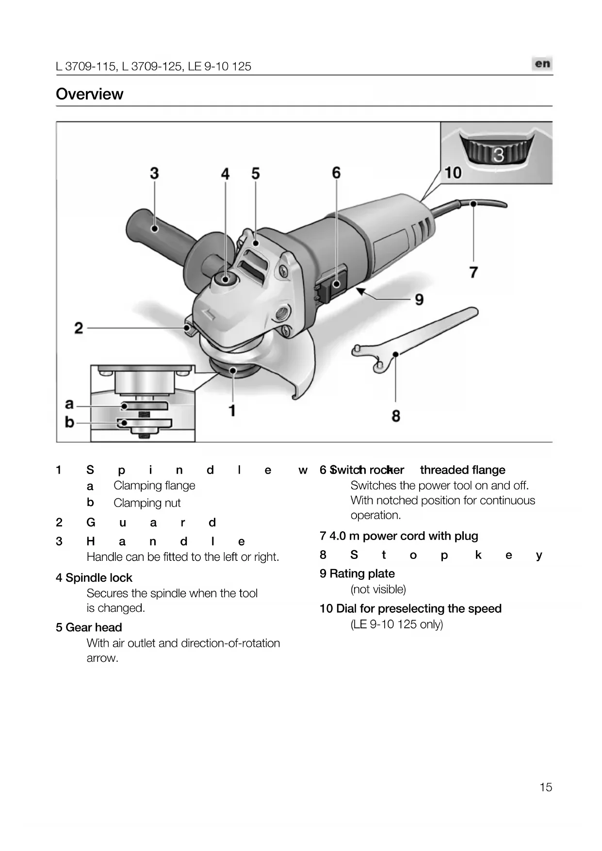
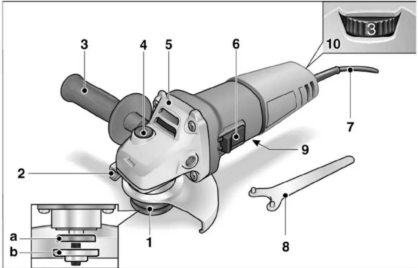
Overview
text_image
3 4 5 6 10 7 9 2 a b 1 81 S p i n d l e w
a Clamping flange
b Clamping nut
2 G u a r d
3 H a n d l e
Handle can be fitted to the left or right.
4 Spindle lock
Secures the spindle when the tool is changed.
5 Gear head
With air outlet and direction-of-rotation arrow.
6 Switch rocker threaded flange
Switches the power tool on and off.
With notched position for continuous operation.
7 4.0 m power cord with plug
8 S t o p k e y
9 Rating plate
(not visible)
10 Dial for preselecting the speed
(LE 9-10 125 only)
For your safety

WARNING!
Before using the angle grinder, please read and follow:
–these operating instructions,
-the "General safety instructions" on the handling of power tools in the enclosed booklet (leaflet-no.:315.915),
–the currently valid site rules and the regulations for the prevention of accidents.
This angle grinder is state of the art and has been constructed in accordance with the acknowledged safety regulations.
Nevertheless, when in use, the power tool may be a danger to life and limb of the user or a third party, or the power tool or other property may be damaged. The angle grinder may be operated only if it is
-used as intended,
-in perfect working order.
Faults which impair safety must be repaired immediately.
Intended use
This angle grinder
– for commercial use in industry and trade,
– is designed for dry grinding and cutting metal and stone,
- is designed for use with grinding tools and accessories which are indicated in this manual or recommended by the manufacturer and which are permitted to run at a circumferential speed of 80 m/s.
Not permitted are e.g. chain cutting wheels, saw blades.
Safety instructions

WARNING!
Read and follow all safety instructions and other instructions in this manual. Failure to observe the warnings and instructions may cause an electric shock, fire and/or serious injuries. Keep this manual in a safe place for subsequent use.
This electric power tool must be used as a grinder and cut-off grinder. Observe all safety information, instructions, diagrams and data which you receive with the power tool.
If you do not observe the following instructions, an electric shock, fire and/or serious injuries may occur.
■ This electric power tool is not suitable for sanding, for use with wire brushes or polishing.
If the electric power tool is not used as intended, the user may be exposed to hazards and may be injured.
■ Never use accessories which the manufacturer did not intend or recommend especially for this electric power tool.
Just because you can attach the accessory to your electric power tool does not guarantee safe use.
■ The permitted speed of the insertion tool must be at least as high as the maximum speed indicated on the electric power tool. An accessory which rotates faster than permitted may shatter and fly off.
■ Outer diameter and thickness of the insertion tool must correspond to the dimensions of the electric power tool. Incorrectly measured insertion tools cannot be adequately shielded or controlled.
■ Sanding discs, sanding pads or other accessories must fit exactly on the grinding spindle of your electric power tool.
Insertion tools, which do not fit exactly on the grinding spindle of the electric power tool, rotate unevenly, vibrate violently and may result in loss of control.
■ Do not use any damaged insertion tools. Before use, always check insertion tools for splinters and cracks, sanding pad for cracks, wear and severe abrasion. If the electric power tool or the insertion tool is dropped, check for damage or use an undamaged insertion tool. When you have checked and inserted the tool, ensure that you and anybody in the vicinity remain outside the plane of the rotating insertion tool and leave the power tool running for one minute at maximum speed.
Damaged insertion tools usually break during this test time.
■ Wear personal protective equipment. Depending on the application, wear full face protection, eye protection or goggles. If appropriate, wear a dust mask, hearing protection, protective gloves and/or a special apron which protect you from small sanding and material particles.
You should protect your eyes from foreign objects which are ejected for different applications. Dust and respirator masks must filter the dust which is generated by the power tool for the particular application. If you are exposed to loud noise for a prolonged period, you may suffer hearing loss.
■ Ensure that other persons are situated at a safe distance from the work area. Anyone who enters the work area must wear personal protective equipment.
Fragments of the workpiece or broken insertion tools may fly off and cause injuries even outside the direct working area.
If the insertion tool is at risk of coming into contact with concealed power cables or the power cord itself, hold the power tool by the insulated grip surfaces only.
Contact with a live cable may also cause metal parts of the appliance to become live and result in an electric shock.
- Keep the power cord away from rotating insertion tools.
If you lose control of the appliance, the power cord could be severed or become caught and your hand or arm may strike the rotating insertion tool.
■ Never put down the electric power tool until the insertion tool has come to a standstill.
The rotating insertion tool may come into contact with the support surface, possibly resulting in you losing control of the electric power tool.
■ Never leave the electric power tool running while you are carrying it.
Your clothing may become caught by accidental contact with the rotating insertion tool which may then drill into your body.
■ Regularly clean the ventilation slots on your electric power tool.
The motor fan draws dust into the housing; a large build-up of metal dust may cause electrical hazards.
■ Never use the electric power tool near combustible materials.
Sparks may ignite these materials.
■ Never use insertion tools which require liquid coolants.
The use of water or other liquid coolants may result in electric shock.
Recoil and appropriate safety instructions
Kickback is the sudden reaction to a pinched or snagged rotating insertion tool, such as a sanding disc, sanding pad, wire brush, etc. Pinching or snagging may cause a rotating insertion tool to stop abruptly. As a result, an uncontrolled electric power tool is accelerated against the direction of rotation of the insertion tool at the blocking point.
For example, if a sanding disc is snagged or pinched by the workpiece, the edge of the sanding disc which is entering the workpiece may become caught and cause the sanding disc to break off or kick back. The sanding disc then moves towards or away from the operator, depending on the direction in which the disc is rotating at the point of pinching. Sanding discs may also break under these conditions.
A recoil occurs if the electric power tool is used incorrectly or improperly. A recoil can be prevented by appropriate precautions as described below.
■ Hold the electric power tool firmly and position your body and arms to allow you to absorb kickback forces. If fitted, always use the auxiliary handle to ensure the best possible control over the recoil forces or reaction torques when acceleration occurs.
The operator can control kickback and reaction forces by taking appropriate precautions.
- Keep your hands away from the rotating insertion tool.
The insertion tool may kickback over your hand.
- Keep your body out of the area into which the electric power tool moves when a recoil occurs.
Kickback propels the electric power tool in the direction opposite to the movement of the sanding disc at the point of pinching.
■ Work especially carefully near corners, sharp edges, etc. Prevent the insertion tool from recoiling off the workpiece and jamming.
The rotating insertion tool has a tendency to snag on corners, sharp edges or if it bounces. This causes a loss of control or kickback.
■ Do not use a chain or toothed saw blade. Such insertion tools frequently cause a kickback or the loss of control of the electric power tool.
Special safety instructions for grinding and cut-off grinding:
■ Use only those sanding tools authorised for use with your electric power tool and the guard designated for this sanding tool.
Sanding tools, which are not designated for use with the electric power tool, cannot be adequately shielded and are unsafe.
■ The guard must be attached securely to the electric power tool and adjusted to ensure maximum safety, i.e. the smallest possible part of the sanding tool is exposed to the operator.
The guard should protect the operator from fragments and accidental contact with the sanding tool.
■ Sanding tools may be used for the recommended applications only. For example: Never grind with the side area of a cutting-off wheel.
Cutting-off wheels are designed to remove material with the edge of the wheel. If a lateral force is applied to these sanding tools, they may shatter.
■ Always use undamaged clamping flanges in the correct size and shape for the grinding disc you have selected.
Suitable flanges support the grinding disc and therefore reduce the risk of the grinding disc breaking. Flanges for cutting-off wheels may differ from the flanges for other grinding discs.
■ Do not use worn grinding discs from larger electric power tools.
Grinding discs for larger electric power tools are not designed for the higher speeds of smaller electric power tools and may break.
Special safety instructions for cut-off grinding:
■ Avoid blocking the cutting-off wheel or exerting too high contact pressure. Do not make excessively deep cuts.
Overloading the cutting-off wheel increases its stress and the susceptibility to twisting or blocking and therefore the possibility of a kickback or the grinding tool breaking.
■ Avoid the area in front of and behind the rotating cutting-off wheel.
When you move the cutting-off wheel in the workpiece away from yourself, a kickback may cause the electric power tool and rotating wheel to be ejected directly towards you.
■ If the cutting-off wheel jams or you interrupt work, switch the power tool off and hold it steady until the wheel has come to a standstill.
Never attempt to pull the still rotating cutting-off wheel out of the cut, otherwise a kickback may occur. Establish and eliminate the cause of the jam.
■ Do not switch the electric power tool on again while it is in the workpiece. First let the cutting-off wheel reach full speed before you carefully continue cutting.
Otherwise, the wheel may jam, jump out of the workpiece or cause a kickback.
■ Be particularly careful when making "pocket cuts" in existing walls or other secluded areas.
When the cutting-off wheel is inserted, it may cause a kickback if it cuts into gas or water lines, electric cables or other objects.
■ Support plates or large workpieces to prevent the risk of a kickback due to the cutting-off wheel jamming.
Large workpieces may sag under their own weight. The workpiece must be supported on both sides of the wheel, namely near the separating cut and along the edge.
Additional safety instructions
■ The mains voltage and the voltage specifications on the rating plate (9) must correspond.
■ Do not press the spindle lock (4) until the grinding tool stops.
Noise and vibration
The noise and vibration values have been determined in accordance with EN 60745.
The A evaluated noise level of the power tool is typically:
– Sound pressure level: 84.6 dB(A);
- Sound power level: 95.6 dB(A);
- Uncertainty:
Total vibration value (when sanding surfaces):
- Emission value: a h = 6.5 m/s^2
Uncertainty: ^2 K

ATTENTION
The indicated measurements refer to new power tools. Daily use causes the noise and vibration values to change.

NOTE
The vibration emission level given in this information sheet has been measured in accordance with a standardised test given in EN 60745 and may be used to compare one tool with another. It may be used for a preliminary assessment of exposure. The declared vibration emission level represents the main applications of the tool. However if the tool is used for different applications, with different accessories or poorly maintained, the vibration emission may differ. This may significantly increase the exposure level over the total working period. For a precise estimation of the vibration load the times should also be considered during which the power tool is switched off or even running, but not actually in use.
This may significantly decrease the exposure level over the total working period. Identify additional safety measures to protect the operator from the effects of vibration such as: maintain the tool and the accessories, keep the hands warm, organisation of work patterns.

Caution
Wear ear protection at a sound pressure above 85 dB(A).
Operating instructions

WARNING!
Before carrying out any work on the angle grinder, always pull out the mains plug.
Before switching on the power tool
Unpack the angle grinder and check that there are no missing or damaged parts.
Switching on and off
K Brief operation without engaged switch rocker:
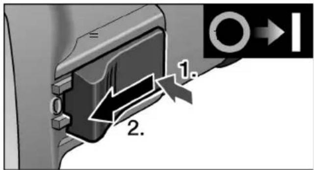
text_image
1. 2.■ Depress switch rocker (6) at back, then push forwards and hold.
■ To switch off the power tool, release the switch rocker (6).
Continuous operation with engaged switch rocker:

CAUTION!
(L 3709-115, L 3709-125)
Following a power failure, the switched-on machine will start running again.
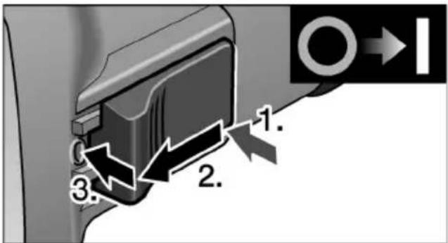
text_image
1. 2. 3.■ Depress switch rocker (6) at back, then press forwards and engage by pressing on the front end.
natural_image
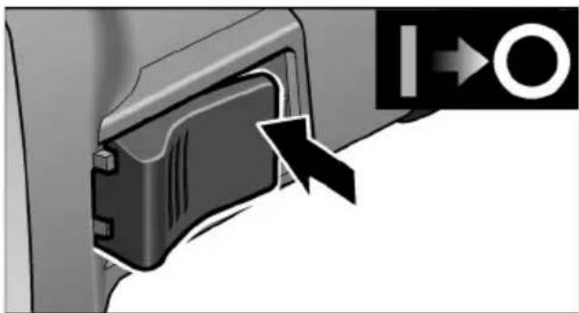
Close-up of a mechanical component with an arrow pointing to a circular symbol (no text or labels visible)■ To switch off the power tool, release the switch rocker (6) by pressing the rear end.
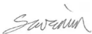
Speed preselection (LE 9-10 125 only)

natural_image
Close-up of a car's front panel with directional arrows and a numbered badge (no text or symbols)To set the operating speed, move the dial (10) to the required value.
Safety guard
(L 3709-115, L 3709-125)

WARNING!
Never remove the safety guard from the angle grinder.
The angle grinder is adapted to the job with the safety guard (2) which can be adjusted without a tool.

CAUTION!
Risk of injury! Wear protective gloves.
■ Pull out the mains plug.
natural_image
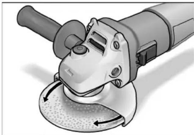
Illustration of a power tool with angular blades and central hub, showing motion arrows (no text or symbols)■ Rotate safety guard to the required position.
Quick-release guard (LE 9-10 125)

WARNING!
When using the angle grinder for roughing orcutting, never work without the guard.
■ Pull out the mains plug.
■ Loosen the clamping lever (a).
■ Adjust the guard.
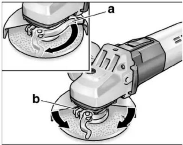
text_image
Technical diagram showing two steps of a power tool operation, labeled a and b, with arrows indicating motion direction.■ Tighten screw (b) until the clamping lever can just be clamped by hand.
■ Retighten the clamping lever.
Attaching or changing the grinding tool
■ Pull out the mains plug.
text_image
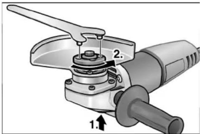
Technical diagram of a power tool with labeled parts and directional arrow indicating assembly or operation■ Press and hold down the spindle lock (1.).
■ Using the stop key, loosen the clamping nut on the spindle in an anti-clockwise direction and remove (2.).
■ Insert the grinding wheel in the correct position.
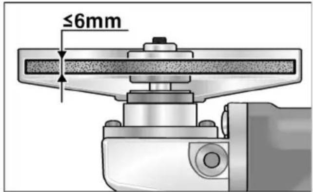
text_image
≤6mm■ Screw the clamping nut (1b), with flange face up, onto the spindle.
■ Press and hold down the spindle lock (4).
■ Tighten the clamping nut (1b) with the stop key.
■ Insert the mains plug into the socket.
■ Switch on the angle grinder (without locking into position) and leave the angle grinder running for approx. 30 seconds. Check for imbalances and vibrations.
■ Switch off the angle grinder.
Operating instructions

NOTE
When the stone grinder is switched off, the grinding tool continues running briefly.
Rough-grinding

WARNING!
Never use cutting-off wheels for rough-grinding.
- Angle of wheel 20–40° for best cutting performance.
- Applying moderate pressure, move the angle grinder backwards and forwards. As a result, the workpiece will not become too hot and there will be no discoloration; nor will there be any grooves.
Cut-off grinding
- Do not press, tilt or oscillate the power tool.
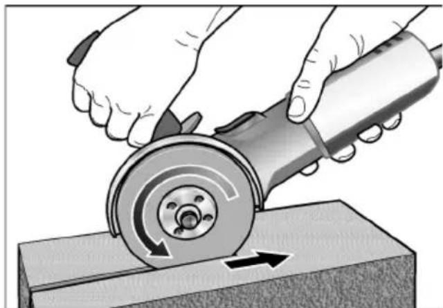
natural_image
Illustration of hands using a grinding tool to cut a circular cutter on a workbench (no text or symbols visible)- Angle grinder must always operate in the counter direction. Otherwise, there is a risk of the angle grinder jumping uncontrollably out of the groove.
- Adjust the feed to the material which is to be work: the harder the material, the slower the feed.
For further information on the manufacturer's products go to www.flex-tools.com.
Maintenance and care

WARNING!
Before carrying out any work on the angle grinder, always pull out the mains plug.
Cleaning

WARNING!
If metals are ground or cut over a prolonged period, conductive dust may become deposited inside the housing. Impairment of the protective insulation! Operate the power tool via a residual-current-operated circuit-breaker (tripping current 30 mA).
Regularly clean the power tool and ventilation slots. Frequency of cleaning is dependent on the material and duration of use.
Regularly blow out the housing interior and motor with dry compressed air.
Carbon brushes
The angle grinder features cut-off carbon brushes.
When the wear limit of the cut-off carbon brushes is reached, the angle grinder switches off automatically.

NOTE
Use only original parts supplied by the manufacturer for replacement purposes. If non-original parts are used, the guarantee obligations of the manufacturer will be deemed null and void.
When the angle grinder is being used, the carbon brushes can be seen sparking through the rear air inlet apertures.
If the carbon brushes spark excessively, switch off the angle grinder immediately. Take the angle grinder to a customer service workshop authorised by the manufacturer.
Gears

NOTE
Do not loosen the screws on the gear head (5) during the warranty period. Non-compliance will deem the guarantee obligations of the manufacturer null and void.
Repairs
Repairs may be carried out by an authorised customer service centre only.
Spare parts and accessories
| Spare-part/Accessory | Order |
| 115 mm guard 335.258 | |
| 125 mm guard 335.266 | |
| Quick-release guard 125 mm 358.029 | |
| Handle 335.274 | |
| Stop key 100.110 | |
| Clamping flange A/F 17 335.282 | |
| Clamping nut 100.080 | |
| FixTec quick-release clamping nut | 313.459 |
| SDS-Clic quick-release clamping nut | 253.049 |
| Metal carrying case 303.224 |
For other accessories, in particular grinding tools, see the manufacturer's catalogues.
Disposal information

WARNING!
Render redundant power tools unusable by removing the power cord.

EU countries only
Do not throw electric power tools into the household waste!
In accordance with the European Directive 2002/96/EG on Waste Electrical and Electronic Equipment and transposition into national law used electric power tools must be collected separately and recycled in an environmentally friendly manner.

NOTE
Please ask your dealer about disposal options!
CE -Declaration of Conformity
no.
We hereby declare that this product corresponds with the following standards or normative documents:
EN 60745 in accordance with the regulations of the directives 2004/108/EC, 2006/42/EC.
Technical file at:
When a new machine is purchased, FLEX issues the end user with a 2-year manufacturer's warranty which comes into force on the date the machine was purchased. The guarantee covers only defects which can be attributed to a material and/or production fault as well as non-performance of warranted characteristics. When making a claim under the guarantee, enclose the original sales receipt with purchase date. Repairs under the guarantee may be carried out only by workshops or service centres authorised by Flex.
A claim may be made under the guarantee only if the power tool has been used as intended. The guarantee excludes in particular operational wear, improper use, partly or completely dismantled machines as well as damage caused by overloading the machine, use of non-permitted, defective or incorrectly used application tools. Damage which is caused by the machine on the application tool or workpiece, use of force, consequential damage which can be attributed to improper or inadequate maintenance on the part of the customer or a third party, damage caused by external effects or foreign objects, e. g. sand or stones, as well as damage caused by non-observance of the operating manual, e. g. connection to an incorrect mains voltage or current type. Claims for insertable tools or accessories can only be made under the guarantee provided they are used with power tools for the intended or permitted use.
Exemption from liability
The manufacturer and his representative are not liable for any damage and lost profit due to interruption in business caused by the product or by an unusable product.
The manufacturer and his representative are not liable for any damage which was caused by improper use of the power tool or by use of the power tool with products from other manufacturers.
Table des matières
natural_image
Close-up of a mechanical component with an arrow pointing to a section, no visible text or symbolsnatural_image
Close-up of a car's front panel with a knob labeled '3' and directional arrows indicating motion (no text or symbols beyond the number)natural_image
Illustration of a power tool with angular blades and a meshing base (no text or symbols)text_image
Technical diagram showing two views (a and b) of a power tool with labeled components, likely illustrating a mechanical or electrical process.text_image
Technical diagram of a power tool with labeled parts and directional arrow indicating movementnatural_image
Illustration of hands using a grinding tool to cut a circular cutter on a workbench (no text or symbols visible)text_image
Technical diagram of a power tool with numbered parts and close-up insets for detailnatural_image
Close-up of a car dashboard with a knob labeled '3' and directional arrows (+/-), no readable text or symbols beyond the number and plus/minus signs.natural_image
Illustration of a power tool with angular blades and a meshing base (no text or symbols)text_image
Technical diagram showing two steps of a robotic grinding process with labeled parts a and btext_image
Technical diagram of a power tool with labeled parts and directional arrow indicating assembly or positioningnatural_image
Illustration of hands using a grinding tool to cut a circular cutter on a workbench (no text or symbols visible)natural_image
Close-up of a mechanical component with an arrow pointing to a section, no visible text or symbolsnatural_image
Close-up of a car's front panel with a handle and directional arrows (no text or symbols)natural_image
Illustration of a power tool with angular blades and a meshing base (no text or symbols)text_image
Technical diagram showing two views (a and b) of a power tool with labeled components, likely illustrating a mechanical or electrical process.text_image
Technical diagram of a power tool with labeled parts and directional arrow indicating assembly or operationnatural_image
Illustration of hands using a grinding tool to cut a circular cutter on a workbench (no text or symbols present)Manager Research & Development (R & D)
Guenter Severin
Manager Quality Department (QD)
11.01.2010
natural_image
Close-up of a mechanical component with an arrow pointing to a section, no visible text or symbolsnatural_image
Illustration of a power tool with angular blades and meshing (no text or symbols)text_image
Technical diagram showing two views (a and b) of a power tool with labeled components, likely illustrating a mechanical or electrical process.text_image
Technical diagram of a power tool with labeled parts and directional arrow indicating assembly or positioningnatural_image
Illustration of hands using a grinding tool to cut a circular cutter on a workbench (no text or symbols)Manager Research & Development (R & D)

Guenter Severin
Manager Quality
Department (QD)
11.01.2010
natural_image
Close-up of a mechanical component with an arrow pointing to a circular symbol (no text or labels visible)natural_image
Close-up of a car dashboard with a stylized '3' badge and directional arrows (no text or symbols)natural_image
Illustration of a power tool with angular blades and a meshing base (no text or symbols)text_image
Technical diagram showing two views (a and b) of a power tool with labeled components, likely illustrating a mechanical or electrical process.text_image
Diagram of a power tool with labeled parts and directional arrow indicating movement or positioningnatural_image
Illustration of hands using a grinding tool to cut a circular cutter on a workbench (no text or symbols visible)Manager Research & Development (R & D)

Guenter Severin
Manager Quality
Department (QD)
11.01.2010
natural_image
Close-up of a mechanical component with an arrow pointing to a section, no visible text or symbolsnatural_image
Close-up of a car's front panel with a numbered knob and directional arrows (no text or symbols)natural_image
Illustration of a power tool with angular blades and a meshing base (no text or symbols)text_image
Technical diagram showing two steps of a grinding or polishing process with labeled components (a and b)text_image
Technical diagram of a power tool with labeled parts and directional arrow indicating movementnatural_image
Illustration of hands using a grinding tool to cut a circular cutter on a workbench (no text or symbols visible)text_image
Technical diagram of a power tool with numbered parts and close-up insets for detailnatural_image
Close-up of a black plastic device with an arrow pointing to it, next to a circular symbol (no text or labels visible)natural_image
Close-up of a car's front panel with a knob labeled '3' and directional arrows (+/-), no readable text or symbols beyond the number.natural_image
Illustration of a power tool with angular workpiece and motion arrows (no text or symbols)text_image
Technical diagram showing two views (a and b) of a power tool with labeled components, likely illustrating a mechanical or electrical process.text_image
Technical diagram of a power tool with numbered parts and directional arrow indicating assembly or operation– Bruk skråvinkel 20–40° for best sliping.
natural_image
Illustration of hands using a grinding tool to cut a circular cutter on a workbench (no text or symbols)Guenter Severin Manager Quality Department (QD)
11.01.2010
text_image
Technical diagram of a power tool with numbered parts and close-up insets for detailnatural_image
Close-up of a mechanical component with an arrow pointing to a section, no visible text or symbolsnatural_image
Close-up of a car dashboard with a stylized '3' badge and directional arrows (no text or symbols)natural_image
Illustration of a power tool with angular blades and a meshing base (no text or symbols)text_image
Technical diagram showing two views (a and b) of a power tool with labeled components, likely illustrating a mechanical or electrical process.text_image
Technical diagram of a power tool with labeled parts and directional arrow indicating movementnatural_image
Illustration of hands using a grinding tool to cut a circular cutter on a workbench (no text or symbols)natural_image
Close-up of a mechanical component with an arrow pointing to a section, no visible text or symbolsnatural_image
Close-up of a car dashboard with directional arrows and a numbered knob (no text or symbols)natural_image
Illustration of a power tool with angular blades and a meshing base (no text or symbols)text_image
Technical diagram showing two views (a and b) of a power tool with labeled components, likely illustrating a mechanical or electrical process.text_image
Technical diagram of a power tool with labeled parts and directional arrow indicating movementnatural_image
Illustration of hands using a grinding tool to cut a circular cutter on a workbench (no text or symbols visible)Manager Research & Development (R & D)

Guenter Severin
Manager Quality
Department (QD)
11.01.2010
natural_image
Close-up of a mechanical component with an arrow pointing to a circular symbol (no text or labels visible)natural_image
Close-up of a car's front panel with a numbered knob and directional arrows (no text or symbols)natural_image
Illustration of a power tool with angular blades and a meshing base (no text or symbols)text_image
Technical diagram showing two views (a and b) of a power tool with labeled components, likely illustrating a mechanical or electrical process.text_image
Technical diagram of a power tool with labeled parts and directional arrow indicating motion or assemblynatural_image
Illustration of hands using a grinding tool to cut a circular cutter on a workbench (no text or symbols visible)Manager Research & Development (R & D)

Guenter Severin
Manager Quality Department (QD)
11.01.2010
text_image
Technical diagram of a power tool with numbered parts and close-up views of the component1 Vida dişli flanşlı mil
a Sabitleme flanşı
b Germe somunu
2 Koruyucu başlık
3 Tutamak
natural_image
Close-up of a mechanical component with an arrow pointing to a section, no visible text or symbolsnatural_image
Close-up of a car's front panel with directional arrows and a numbered badge (no text or symbols)natural_image
Illustration of a power tool with angular blades and a meshing base (no text or symbols)text_image
Technical diagram showing two views (a and b) of a power tool with labeled components, likely illustrating a mechanical or electrical process.text_image
Technical diagram of a power tool with labeled parts and directional arrow indicating movementnatural_image
Illustration of hands using a grinding tool to cut a circular cutter on a workbench (no text or symbols present)Manager Research & Development (R & D)

Guenter Severin Manager Quality Department (QD)
11.01.2010
text_image
Technical diagram of a power tool with numbered parts and close-up views of the componentnatural_image
Close-up of a mechanical component with an arrow pointing to a section, no visible text or symbolsnatural_image
Illustration of a power tool with angular blades and a meshing base (no text or symbols)text_image
Technical diagram showing two views (a and b) of a power tool with labeled components, likely illustrating a mechanical or electrical process.text_image
Technical diagram of a power tool with labeled parts and directional arrow indicating motionnatural_image
Illustration of hands using a grinding tool to cut a circular cutter on a workbench (no text or symbols visible)Guenter Severin Manager Quality Department (QD)
11.01.2010
natural_image
Close-up of a mechanical component with an arrow pointing to a section, no visible text or symbolsnatural_image
Close-up of a car dashboard with directional arrows and a numbered badge (no text or symbols)natural_image
Illustration of a power tool with angular blades and a meshing base (no text or symbols)text_image
Technical diagram showing two views (a and b) of a power tool with labeled components, illustrating mechanical or electrical process.text_image
Technical diagram of a power tool with labeled parts and directional arrow indicating movementnatural_image
Illustration of hands using a grinding tool to cut a circular cutter on a workbench (no text or symbols visible)Manager Research & Development (R & D)

Guenter Severin
Manager Quality Department (QD)
11.01.2010
$$ K \quad = 3, 0 $$
$$ K \quad = \quad 1, 5 $$
Návod k použití

VAROVÁNÍ!
natural_image
Close-up of a mechanical component with an arrow pointing to a section, no visible text or symbolsnatural_image
Close-up of a car's front panel with a knob labeled '3' and directional arrows (+/-), no readable text or symbols beyond the number.natural_image
Illustration of a power tool with angular workpiece and motion arrows (no text or symbols)text_image
Technical diagram showing two steps of a robotic grinding process, labeled a and b, with arrows indicating rotation or movement.text_image
Technical diagram of a power tool with labeled parts and directional arrow indicating movementnatural_image
Illustration of hands using a grinding tool to cut a circular cutter on a workbench (no text or symbols visible)2004/108/ES, 2006/42/ES.
natural_image
Close-up of a car dashboard with directional arrows and a numbered badge (no text or symbols)natural_image
Illustration of a power tool with angular blades and a meshing base (no text or symbols)text_image
Technical diagram showing two steps of a power tool operation, labeled a and b, with arrows indicating rotation or movement.■ Utiahnite skrutku (b) tak pevne, aby sa upínacia páka dala ešte rukou upnúť.
■ Upínaciu páku opät' pevne utiahnite.
text_image
Technical diagram of a power tool with labeled parts and directional arrow indicating movementnatural_image
Illustration of hands using a grinding tool to cut a circular cutter on a workbench (no text or symbols visible)Manager Research & Development (R & D)

Guenter Severin
Manager Quality Department (QD)
11.01.2010
natural_image
Close-up of a mechanical component with an arrow pointing to a circular symbol (no text or labels visible)■ Radi isključivanja ozibnu sklopku (6) deblokirati pritiskom na zadnji kraj.
Predbiranje broja okretaja (samo LE 9-10 125)
natural_image
Close-up of a car's front panel with a handle and directional arrows (no text or symbols)Radi namještanja radnog broja okretaja kotač za namještanje (10) postaviti na željenu vrijednost.
Sigurnosno-zaštitna kapa (L 3709-115, L 3709-125)

OPASNOST!
Sigurnosno-zaštitnu kapu nikada ne demontirati sa kutne brusilice.
Radi uskladjivanja s radnom zadaćom se sigurnosno-zaštitnu kapu (2) može namještati bez alata.

OPREZ!
natural_image
Illustration of a power tool with angular blades and a meshing base (no text or symbols)■ Sigurnosno-zaštitnu kapu okrenuti do potrebnoga položaja.
Brzozatezna kapa (LE 9-10 125)

OPASNOST!
text_image
Technical diagram showing two views (a and b) of a power tool with labeled components, likely illustrating a mechanical or electrical process.Vijak (b) pritegnuti tako da se zateznu polugu može samo još ručno zategnuti.
■ Zateznu polugu ponovno čvrsto zategnuti.
text_image
Technical diagram of a power tool with labeled parts and directional arrow indicating assembly or positioningnatural_image
Illustration of hands using a grinding tool to cut a circular cutter on a workbench (no text or symbols present)Manager Research & Development (R & D)

Guenter Severin
Manager Quality Department (QD)
11.01.2010
natural_image
Close-up of a mechanical component with an arrow pointing to a section, no visible text or symbolsnatural_image
Illustration of a power tool with angular blades and a meshing base (no text or symbols)text_image
Technical diagram showing two views (a and b) of a grinding tool with labeled components, likely illustrating a lathe or grinding process.text_image
Technical diagram of a power tool with labeled parts and directional arrow indicating assembly or positioningnatural_image
Illustration of hands using a grinding tool to cut a circular cutter on a workbench (no text or symbols visible)Manager Research & Development (R & D)

Guenter Severin
Manager Quality
Department (QD)
11.01.2010