GE 7 - Grinder Flex - Free user manual and instructions
Find the device manual for free GE 7 Flex in PDF.
Frequently Asked Questions - GE 7 Flex
User questions about GE 7 Flex
0 question about this device. Answer the ones you know or ask your own.
Ask a new question about this device
Download the instructions for your Grinder in PDF format for free! Find your manual GE 7 - Flex and take your electronic device back in hand. On this page are published all the documents necessary for the use of your device. GE 7 by Flex.
USER MANUAL GE 7 Flex
natural_image
Illustration of a handheld electric shock absorber with two wheels (no text or symbols)de Originalbetriebsanleitung .... 3
en Original operating instructions ..... 16
fr Notice d'instructions d'origine 29
it Istruzioni per l'uso originali ..... 43
es Instrucciones de funcionamiento originales ..... 56
pt Instruções de serviço originais ..... 69
nl Originele gebruiksaanwijzing 82
da Originale driftsvejledning 95
no Originale driftsanvisningen ..... 108
sv Originalbruksanvisning 121
fi Alkuperäinen käyttöohjekirja 134
el Auθεντικές οδηγίες χειρισμού ..... 147
tr Orijinal işletme kılavuzu 161
pI Instrukcja oryginalna 174
hu Eredeti üzemeltetési útmutató ..... 189
cs Originální návod k obsluze ..... 202
sk Originálny návod na obsluhu 215
hr Originalna uputa za rad 228
sl Izvirno navodilo za obratovanje 241
ro Instructiuni de functionare originale ..... 254
bg Оригинално упътване за експлоатация ..... 267
ru Оригинальная инструкция по эксплуатации ..... 282
et Originaalkasutusjuhend 297
It Originali naudojimo instrukcija .... 310
Iv Lietošanas pamācības oriģināls ..... 323
ar إرشادات التشفيل الأصلية 347
Inhalt
Verwendete Symbole .... 3
natural_image
Illustration of a hand holding a flexible hose with a cord, emitting a 'click' button (no text or symbols on the diagram itself)text_image
Technical diagram showing mechanical assembly with numbered components and directional arrows indicating motion or forcei HINWEIS
natural_image
Illustration of hands placing a circular object onto a mesh plate with an arrow indicating rotation (no text or symbols)natural_image
Close-up of a handheld electric shaver with a cable and directional arrow indicator (no text or symbols)Gerät ausschalten:
text_image
Diagram showing a hand holding a tool with a keypad and a magnified view of the pad switch, indicating disassembly or reassembly.text_image
1. "clic" 2.natural_image
Illustration of two hands using a handheld fuel pump against a plain background (no text or symbols)
VORSICHT!
natural_image
Illustration of a hand using a fuel pump to lift a wall, showing airflow direction (no text or symbols)natural_image
Illustration of hands operating a CD or DVD disc with a knob (no text or symbols visible)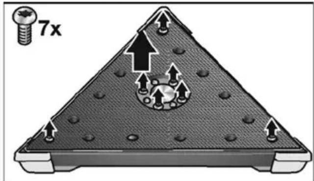
text_image
7xnatural_image
Cross-sectional diagram of a mechanical device with internal components and mounting holes (no text or symbols)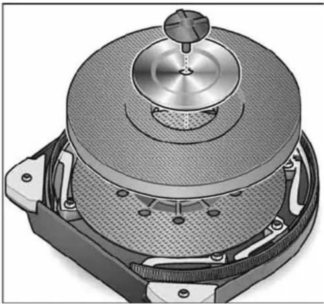
natural_image
Cross-sectional diagram of a mechanical device with a central hub and internal components (no text or symbols visible)
natural_image
Cross-sectional diagram of a mechanical assembly with bolt holes and a triangular base (no text or symbols)natural_image
Cross-sectional diagram of a circular mechanical component with internal mesh structure and mounting points (no text or symbols)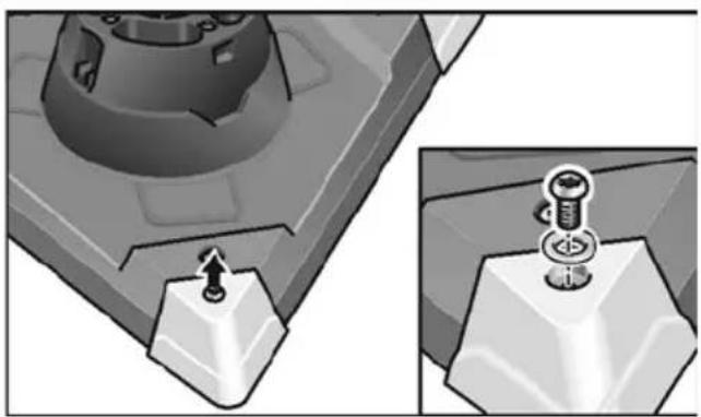
natural_image
Mechanical assembly diagram showing a bolt and screw inserted into a block, with no visible text or symbolsKlaus Peter WeinperEckhard F Manager Research & Development (R & D) Head of Quality Department (QD)
Symbols used in this manual ..... 16
Symbols on the power tool ..... 16
For your safety 16
Noise and vibration 18
Technical specifications 19
Overview 20
Instructions for use 21
Operating instructions 24
Maintenance and care 25
Disposal information. 27
C ∈ Declaration of Conformity ..... 27
UK Declaration of Conformity ..... 28
Exemption from liability 28
Symbols used in this manual

WARNING!
Denotes impending danger.
Non-observance of this warning may result in death or extremely severe injuries.

CAUTION!
Denotes a possibly dangerous situation.
Non-observance of this warning may result in slight injury or damage to property.

NOTE
Denotes application tips and important information.
Symbols on the power tool

Before switching on the power tool, read the operating manual!
Wear goggles!

Disposal information for the old machine (see page 27)!
For your safety

WARNING!
Before using the power tool, please read and follow:
– these operating instructions,
- the "General safety instructions" on the handling of power tools in the enclosed booklet (leaflet-no.: 315.915),
– the currently valid site rules and the regulations for the prevention of accidents.
This power tool is state of the art and has been constructed in accordance with the acknowledged safety regulations. Nevertheless, when in use, the power tool may be a danger to life and limb of the user or a third party, or the power tool or other property may be damaged.
The power tool may be operated only if it is
- as intended,
- in perfect working order.
Faults which impair safety must be repaired immediately.
Intended use
The wall sander GE 7 is designed
– for commercial use in industry and trade,
– for sanding walls and ceilings inside and outside,
– for sanding smoothed drywalls,
– for use with tools which FLEX offer for these power tools and which are authorised to run at a speed of at least 1750 r.p.m.
It is not permitted to use cutting-off wheels, roughing wheels, fan-like grinding wheels or wire brushes.
When using the wall sander GE 7, connect a Class M dust extractor.
Safety instructions

WARNING!
Read all safety warnings and all instructions.
Failure to follow the warnings and instructions may result in electric shock, fire and/or serious injuries. Save all warnings and instructions for future reference.
■ This power tool is intended to function as a sander. Read all safety warnings, instructions, illustrations and specifications provided with this power tool.
Failure to follow all instructions listed
below may result in electric shock, fire and/or serious injury.
■ Operations such as grinding, wire brushing, or for polishing and cut-off are not recommended to be performed with this power tool. Operations for which the power tool was not designed may create a hazard and cause personal injury.
- Do not use accessories which are not specifically designed and recommended by the tool manufacturer. Just because the accessory can be attached to your power tool, it does not assure safe operation.
■ The rated speed of the accessory must be at least equal to the maximum speed marked on the power tool. Accessories running faster than their rated speed can break and fly apart.
■ The outside diameter and the thickness of your accessory must be within the capacity rating of your power tool. Incorrectly sized accessories cannot be adequately guarded or controlled.
Threaded mounting of accessories must match the grinder spindle thread. For accessories mounted by flanges, the arbour hole of the accessory must fit the locating diameter of the flange. Accessories that do not match the mounting hardware of the power tool will run out of balance, vibrate excessively and may cause loss of control.
- Do not use a damaged accessory. Before each use inspect the accessory such as abrasive wheels for chips and cracks, backing pad for cracks, tear or excess wear, wire brush for loose or cracked wires. If power tool or accessory is dropped, inspect for damage or install an undamaged accessory. After inspecting and installing an accessory, position yourself and bystanders away from the plane of the rotating accessory and run the power tool at maximum no-load speed for one minute. Damaged accessories will normally break apart during this test time.
■ Wear personal protective equipment. Depending on application, use face shield, safety goggles or safety glasses. As appropriate, wear dust mask, hearing protectors, gloves and workshop apron
capable of stopping small abrasive or workpiece fragments. The eye protection must be capable of stopping flying debris generated by various operations. The dust mask or respirator must be capable of filtrating particles generated by your operation. Prolonged exposure to high intensity noise may cause hearing loss.
- Keep bystanders a safe distance away from work area. Anyone entering the work area must wear personal protective equipment. Fragments of workpiece or of a broken accessory may fly away and cause injury beyond immediate area of operation.
- Hold power tool by insulated gripping surfaces only, when performing an operation where the cutting accessory may contact hidden wiring or its own cord. Cutting accessory contacting a “live” wire may make exposed metal parts of the power tool “live” and shock the operator.
■ Position the cord clear of the spinning accessory. If you lose control, the cord may be cut or snagged and your hand or arm may be pulled into the spinning accessory.
■ Never lay the power tool down until the accessory has come to a complete stop. The spinning accessory may grab the surface and pull the power tool out of your control.
■ Do not run the power tool while carrying it at your side. Accidental contact with the spinning accessory could snag your clothing, pulling the accessory into your body.
■ Regularly clean the power tool's air vents. The motor's fan will draw the dust inside the housing and excessive accumulation of powdered metal may cause electrical hazards.
■ Do not operate the power tool near flammable materials. Sparks could ignite these materials.
■ Do not use accessories that require liquid coolants. Using water or other liquid coolants may result in electrocution or shock.
Kickback and Related Warnings
Kickback is a sudden reaction to a pinched or snagged rotating wheel, backing pad, brush or any other accessory. Pinching or snagging causes rapid stalling of the rotating accessory which in turn causes the uncontrolled power tool to be forced in the direction opposite of the accessory's rotation at the point of the binding.
For example, if an abrasive wheel is snagged or pinched by the workpiece, the edge of the wheel that is entering into the pinch point can dig into the surface of the material causing the wheel to climb out or kick out. The wheel may either jump toward or away from the operator, depending on direction of the wheel's movement at the point of pinching. Abrasive wheels may also break under these conditions.
Kickback is the result of power tool misuse and/or incorrect operating procedures or conditions and can be avoided by taking proper precautions as given below.
■ Maintain a firm grip on the power tool and position your body and arm to allow you to resist kickback forces.
Always use auxiliary handle, if provided, for maximum control over kickback or torque reaction during start-up.
The operator can control torque reactions or kickback forces, if proper precautions are taken.
■ Never place your hand near the rotating accessory. Accessory may kickback over your hand.
- Do not position your body in the area where power tool will move if kickback occurs. Kickback will propel the tool in direction opposite to the wheel's movement at the point of snagging.
■ Use special care when working corners, sharp edges etc. Avoid bouncing and snagging the accessory. Corners, sharp edges or bouncing have a tendency to snag the rotating accessory and cause loss of control or kick-back.
■ Do not attach a saw chain woodcarving blade or toothed saw blade. Such blades create frequent kickback and loss of control.
Special safety instructions for sanding:
■ Do not use excessively oversized sanding disc paper. Follow manufacturers recommendations, when selecting sanding paper. Larger sanding paper extending beyond the sanding pad presents a laceration hazard and may cause snagging, tearing of the disc or kickback.
Additional safety instructions
■ Use only extension cables permitted for outdoor use.
■ It is not recommended to sand lead paint. Lead paint should be removed by a specialist only.
If plaster board or plaster is sanded, this may cause static electricity to build up on the tool. To ensure your safety, the wall sander is earthed.
Remove dust with an earthed dust extractor only.
- Do not work on materials which release hazardous substances (e.g. asbestos). Take precautions if hazardous, combustible or explosive dust is likely to occur. Wear protective dust mask. Use dust extraction system.
Damage to property!
The mains voltage and the voltage specifications on the rating plate must correspond.
Noise and vibration
i NOTE
Values for the A-weighted sound pressure level and for the total vibration values can be found in the “Technical specifications” table. The noise and vibration values have been determined in accordance with EN 60745.
CAUTION!
The indicated measurements refer to new power tools. Daily use causes the noise and vibration values to change.
i NOTE
The vibration emission level given in this information sheet has been measured in accordance with a standardised test given in EN 60745 and may be used
to compare one tool with another. It may be used for a preliminary assessment of exposure. The declared vibration emission level represents the main applications of the tool. However if the tool is used for different applications, with different accessories or poorly maintained, the vibration emission may differ. This may significantly increase the exposure level over the total working period. However if the tool is used for different applications, with different accessories
or poorly maintained, the vibration emission may differ. This may significantly decrease the exposure level over the total working period. Identify additional safety measures to protect the operator from the effects of vibration such as: maintain the tool and the accessories, keep the hands warm, organisation of work patterns.

CAUTION!
Wear ear protection at a sound pressure above 85 dB(A).
Technical specifications
| Machine type | Wall sander with | ||||
| round head | round head close to edge | delta head | orbital head | ||
| Protection class I | |||||
| Power input W 710 | |||||
| Length mm 1520 | |||||
| Weight (without power cord) kg | 4.2 4.4 4.5 | ||||
| Suction hose/length x diameter | mm 4000x32 | ||||
| No load speed r.p.m. | 1100–1650 | - | - | ||
| Rated speed | r.p.m. | 2600 | - | - | |
| Idling speed | r.p.m. | - | 3800-5700 | 3100-4600 | |
| Sanding plate diameter | mm | 225 | - | 225 | |
| Edge length | mm | - | 295 | - | |
| Sanding stroke | mm | - | 4 | ||
| A-weighted sound pressure level according to EN 60745 (see “Noise and vibration”): | |||||
| Sound pressure level L_pA | dB(A) | 74 | 78 | 78 | |
| Sound power level L_WA | dB(A) | 85 | 89 | 89 | |
| Uncertainty K | dB | 3 | |||
| Total vibration value according to EN 60745 (see “Noise and vibration”): | |||||
| Emmission value a_h when sanding smoothed plasterboard walls | m/s^2 | < 2.5 | < 2.5 | < 2.5 | |
| Uncertainty K | m/s^2 | 1.5 | |||
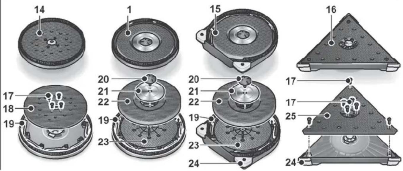
Overview
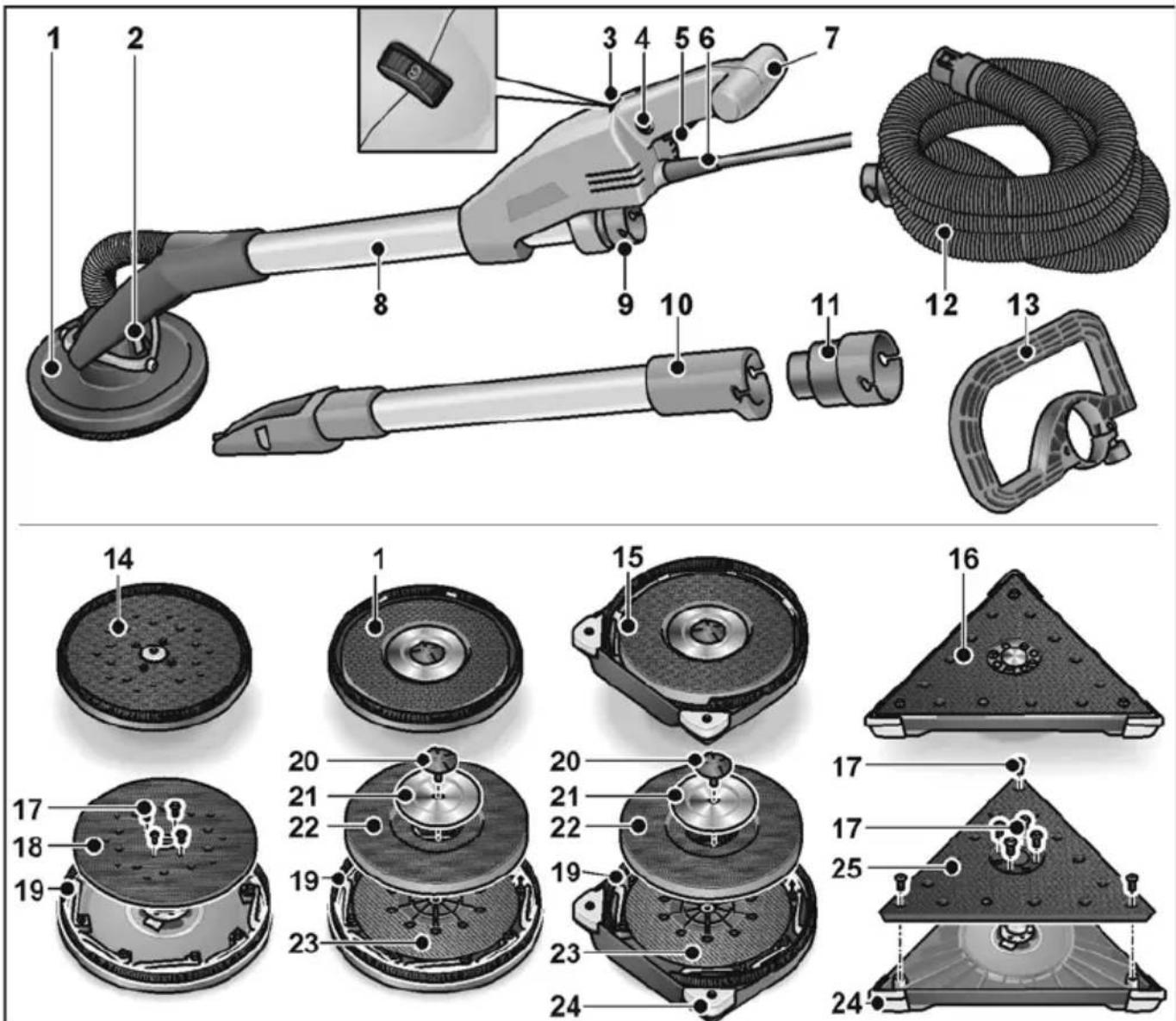
1 Sanding head
with closed brush ring
2 Gimbal bearings
3 Dial for preselecting the speed
4 Locking button
5 S w i t c h
6 5.0 m power cord with plug
7 Handle
8 Tubular handle
9 32 mm connection
10 Extension tube (optional)
11 Adapter for extraction hose (optional) for connection of electric power tools using conventional connection piece
12 Suction hose
13 Bail handle (optional)
14 Orbital sander head
15 Sanding head
with open brush ring for sanding edges
16 Delta sander head
17 Fastening screws
18 Orbital Velcro plate
19 Brush ring
20 Screw
21 Retaining washer
22 Velcro pad
23 Backing pad
24 Replaceable protective corners
25 Delta Velcro plate
Instructions for use
Before switching on the power tool
■ Unpack power tool and accessories and check that no parts are missing or damaged.
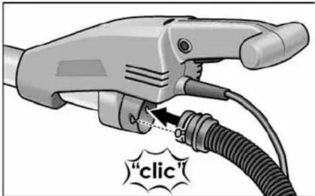
Connecting the extractor
text_image
"clic"■ Connect extraction hose to the 32 mm connector.
i NOTE
The connection piece of the GE 7 is a new development. If electric power tools are used with conventional connection pieces together with the extraction hose of the GE 7, an adapter from the FLEX accessories programme can be used.
Attaching/changing the sanding head
CAUTION!
Before performing any work on the electric power tool, pull out the mains plug.
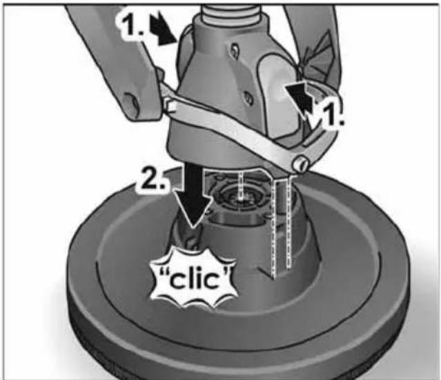
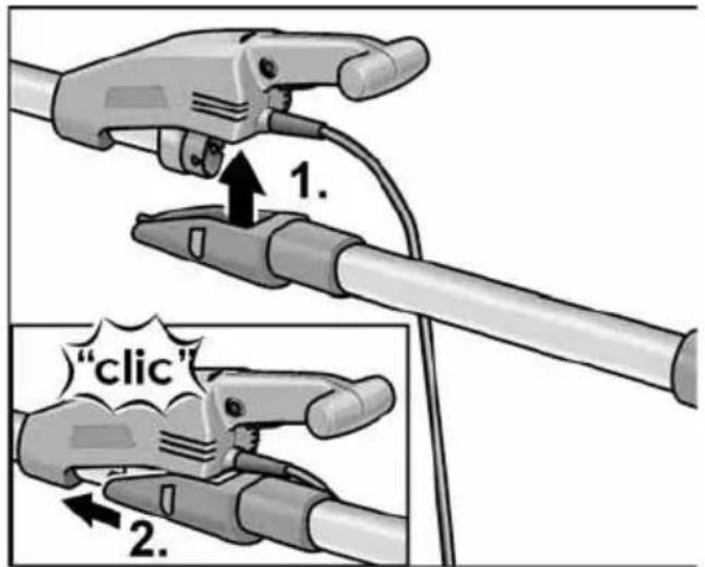
To attach:
■ Press the two locks on the tool change head (1.).
■ Put the tool change head on the sanding head (2.).
■ Check that the locking mechanisms have returned to the home position.
text_image
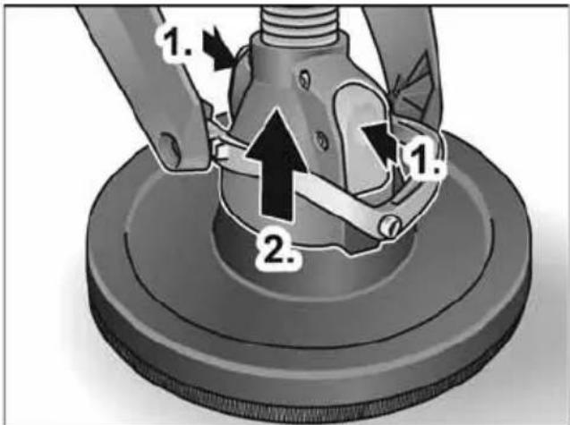
1. 2. 1. 2. "click"To change:
■ Press the two locks on the tool change head (1.) and remove sanding head (2.).
text_image
Diagram of a mechanical device with numbered parts and directional arrows indicating motion or assembly.i NOTE
The delta sander head and orbital sander head are attached/changed in the same way.
Using a dust extraction system
CAUTION!
- When using the wall sander, connect a Class M dust extractor.
- If a dust bag is used which is not authorised for use with dry construction dust, the amount of dust particles in the air may increase at the work place.
Over a prolonged period high concentrations of dust in the air may damage the human respiratory system.
■ Insert the special dust bag for dry construction dust into your dust extractor according to the instructions supplied with the dust extractor.
■ Connect extraction hose to the dust extraction system. Follow the operating instructions for the dust extraction system! Check the attachment!
If required, use an appropriate adapter.
i NOTE
If your dust extractor requires a special connector, the clip-on connection can be removed and a matching adapter selected from the FLEX accessories range.
Attaching and changing the sanding tools
CAUTION!
Before performing any work on the electric power tool, pull out the mains plug.
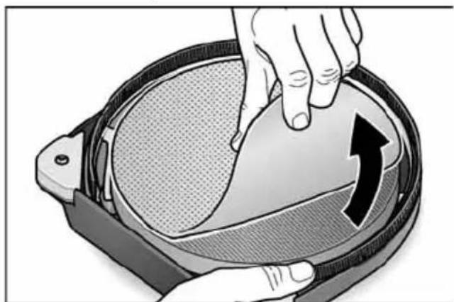
■ Remove worn sanding tool from the Velcro pad.
natural_image
Illustration of hands placing a circular object onto a textured surface with an arrow indicating rotation (no text or symbols)■ Place the sanding sheet in the centre of the Velcro pad and press on.
■ Conduct a test run to check that the sanding tool is clamped in the centre.
CAUTION!
Never use the Velcro pad as a sanding tool. Never use the wall sander without the sanding sheet, otherwise the work surface will be seriously damaged!
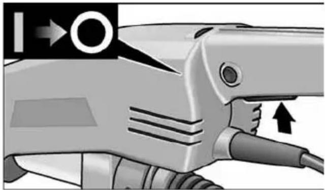
Switching the electric power tool on and off
text_image
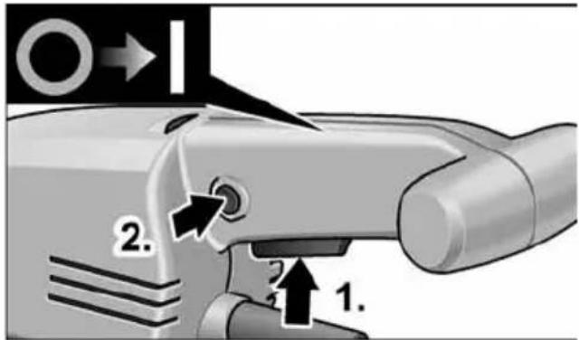
2. 1.Switch on the machine:
■ Press the switch (1.).
■ To engage, press the locking button and release switch (2.).
natural_image
Close-up of a handheld electric shock absorber with labeled ports and an arrow indicating direction (no text or symbols present)Switch off the machine:
■ Press the switch briefly
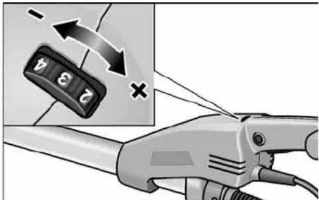
Preselecting the speed
text_image
Diagram showing a hand holding a car with a keypad and a magnified view of the keypad with arrows indicating rotation or change.To set the operating speed, move the dial to the required value.
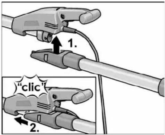
Using extension (optional)
An extension tube is available for the wall sander GE 7. The extension tube can be used to increase the range when working with the wall sander.
text_image
1. "clic" 2.■ Attach extension tube from below to the housing of the wall sander (1.) and push it forwards until it engages (2.).
text_image
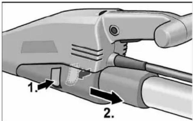
1. 2.■ To remove, press in both catches (1.) and remove extension tube (2.).
Using bar-type handle (optional)
To stabilise the working position, it is possible to mount a bar-type handle on the handle tube. The mounting position can be determined individually.
Using adapter for suction hose (optional)
The adapter can be used for connecting suction hoses of different dimensions.
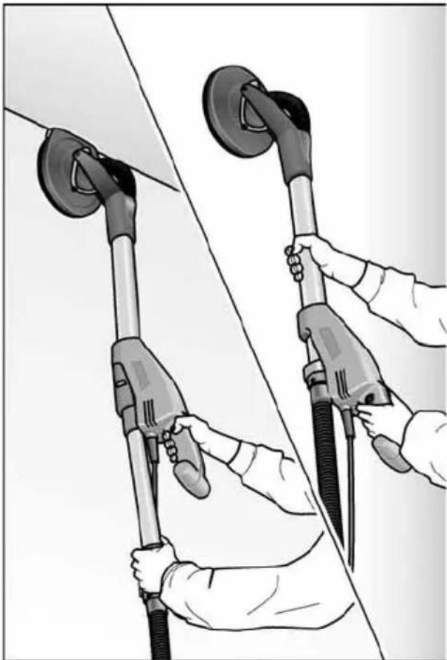
Working with the power tool
CAUTION!
Hold the electric power tool with both hands! When working, always have one hand on the handle – even when working with attached extension. Keep your hands away from the sanding head.
Otherwise, your hand could become caught, as the sanding head swivels in different directions.
- Attach sanding tool.
- Connect dust extraction system.
- Insert mains plug.
- Set required speed.
-
Switch on dust extraction system.
-
Hold the wall sander with both hands. This provides the best possible combination of range and leverage for the application.
-
Switch on the device.
-
Press the wall sander gently against the work surface (the pressure should be just enough to ensure that the sanding head is flush with the work surface).
-
Increase the pressure to bring the sanding sheet into contact with the work surface. In doing so, swing the sander in overlapping movements to smooth the surface to the required fineness.
natural_image
Illustration of two hands using a handheld fuel pump against a plain background (no text or symbols)
CAUTION!
The rotating parts of the sanding head must not come into contact with sharp projecting objects (e.g. nails, screws, junction boxes). The Velcro pad may be damaged if it comes into contact with projecting objects.
The Velcro pad can be replaced if it is damaged or severely abraded (see section entitled "Maintenance and care").
Operating instructions
Brush ring
A brush-type ring surrounds the sanding head. This ring has two functions:
- As the ring projects above the surface of the sanding plate, it is the ring which comes into contact with the work surface first. As a result, the sanding head is brought parallel to the work surface before the sanding tool comes into contact with the work surface.
This avoids a sickle-shaped depression caused by the edge of the sanding disc.
- The ring also retains the dust until it is extracted by the dust extractor.
If the brush ring is damaged or shows excessive wear, it should be replaced (see section entitled “Maintenance and care”). Replacement brush rings are available from any FLEX customer service centre.
Sanding in dry construction
The wall sander features a unique swivel head. As this head can swivel in different directions, the sanding head can be adjusted to the work surface.
As a result, the user can sand the upper, middle and lower wall areas or ceiling profiles without having to change his position. When working, apply only as much pressure as is required to keep the sanding plate in contact with the work surface. Excessive pressure may result in a disagreeable spiral pattern of scratches and an uneven work surface.
Move the sander constantly while the sanding plate is in contact with the work surface. In doing so, ensure that you move the sander evenly and over a wide area. If you stop the sander on the work surface or move the sander unevenly, this may result in a disagreeable spiral pattern of scratches and an uneven work surface.

NOTE
The wall sander features an overload cut-out for protecting the device.
If the load is too great, the device switches off and immediately restarts.
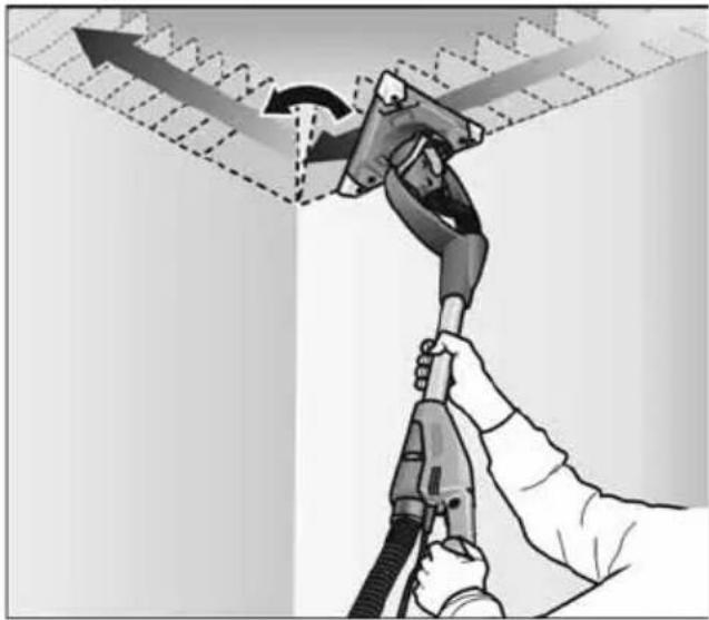
Triangular sanding head
The triangular sanding head does not rotate, but vibrates.
natural_image
Illustration of a hand using a fuel pump to lift a vehicle, showing motion and safety (no text or symbols)As the triangular sanding head can revolve on bearings, it can sand right into the corners of the wall/ceiling.
Maintenance and care

WARNING!
Before performing any work on the electric power tool, pull out the mains plug.
Cleaning

WARNING!
Do not use water or liquid detergents.
■ Regularly blow out the housing interior and motor with dry compressed air.
■ Blow out the sanding head and gimbal bearing with dry compressed air.
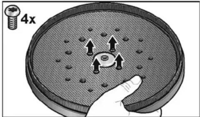
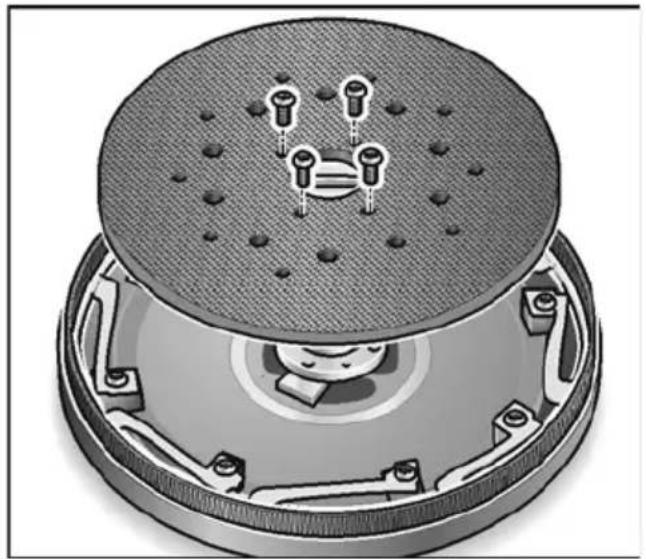
Replacing Velcro or backing pad
■ Take hold of the sanding plate together with the sanding head to prevent the sanding plate from turning.
text_image
4x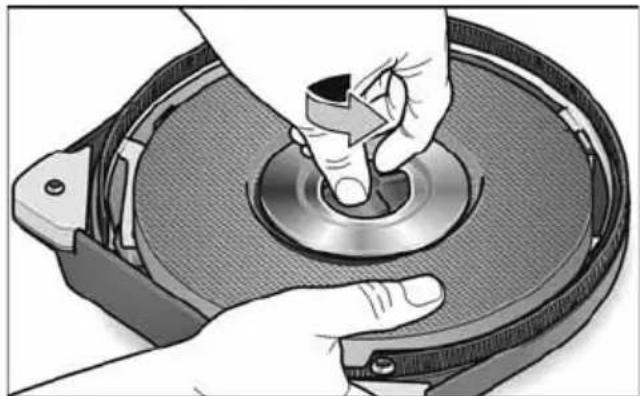
natural_image
Illustration of hands operating a CD or DVD disc with a knob (no text or symbols visible)
text_image
7x■ Turn the bolts in anti-clockwise direction and remove.
■ The Velcro plates can be detached/removed.
natural_image
Cross-sectional diagram of a mechanical component with internal parts and mounting holes (no text or symbols)
natural_image
Technical illustration of a mechanical device with a central knob and textured base (no text or symbols)
natural_image
Diagram of a mechanical assembly with a triangular base and internal components, no visible text or symbols- Replace parts.
■ Assemble sanding head in reverse sequence.
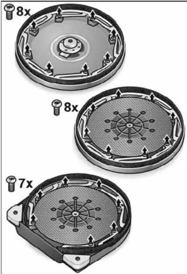
Replacing the brush ring
■ Remove the sanding head (see section "Replacing Velcro or backing pad").
text_image
8x 8x 7x■ Loosen the retaining screws.
■ Take the ring out of the housing.
■ Insert a new brush ring into the housing and screw in the retaining screws.
■ Assemble sanding head in reverse sequence.
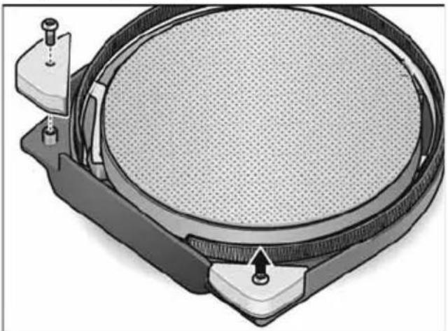
Replacing the protective corners
natural_image
Technical illustration of a circular mechanical component with internal mesh structure and mounting points (no text or symbols)
natural_image
Mechanical assembly diagram showing a bolt and nut assembly with a pin inserted into a base (no text or symbols)■ Remove protective corners to be replaced.
■ Attach new protective corners.
In the corners reduce the contact pressure, otherwise there will be excessive load on the tips of the triangular sanding disc.
Heavily worn corners of the triangular sanding head can easily be replaced.
Repairs
Repairs may be carried out by an authorised customer service centre only.
i NOTE
During the warranty period do not loosen the screws on the housing. Non-compliance will deem the guarantee obligations of the manufacturer null and void.
Spare parts and accessories
Other accessories, in particular insertion tools, can be found in the manufacturer's catalogues.
Exploded drawings and spare-part lists can be found on our homepage:
www.flex-tools.com
Disposal information
WARNING!
Render redundant power tools unusable by removing the power cord.

EU countries only Do not throw electric power tools into the household waste!
In accordance with the European Directive 2012/19/EU on Waste Electrical and Electronic Equipment and transposition into national law used electric power tools must be collected separately and recycled in an environmentally friendly manner.
i NOTE
Please ask your dealer about disposal options!
CE Declaration of Conformity
We declare under our sole responsibility that the product described under "Technical specifications" conforms to the following standards or normative documents:
EN 60745 in accordance with the regulations of the directives 2014/30/EU, 2006/42/EC, 2011/65/EU.
Responsible for technical documents: FLEX-Elektrowerkzeuge GmbH, R & D Bahnhofstrasse 15, D-71711 Steinheim/Murr

text_image
Rille B B DManager Research & Development (R & D)
Head of Quality Department (QD)
11.03.2019
Declaration of Conformity
We as the manufacturer: FLEX
Business address: Bahnhofstr. 15,
71711 Steinheim, Germany
declare under our sole responsibility, that the product(s) described under „Technical specifications“ fulfills all the relevant provisions of The Supply of Machinery (Safety) Regulations S.I. 2008/1597 and also fulfills all the relevant provisions of the following UK Regulations:
Electromagnetic Compatibility Regulations S.I. 2016/1091, The Restriction of the Use of Certain Hazardous Substances in Electrical and Electronic Equipment Regulations S.I. 2012/3032 and are manufactured in accordance with the following designated Standards: BS EN 60745-1:2010,
BS EN 60745-2-3:2011, BS EN 55014-1:2017,
BS EN 55014-2:2015, BS EN61000-3-2:2014,
BS EN 61000-3-3:2013
Place of declaration: Steinheim, Germany.
Responsible person: Peter Lameli,
Contact details for Great Britain:
FLEX Power Tools Limited,
Unit 8 Anglo Office Park, Lincoln Road,
HP 12, 3RH Buckinghamshire,
United Kingdom.

Peter Lameli Technical Head

text_image
Bolts Q - 1Klaus Peter Weinper
Head of Quality
Department (QD)
19.05.2021
Exemption from liability
The manufacturer and his representative are not liable for any damage and lost profit due to interruption in business caused by the product or by an unusable product.
The manufacturer and his representative are not liable for any damage which was caused by improper use of the product or by use of the product with products from other manufacturers.
Table des matières
text_image
Technical diagram showing mechanical assembly with numbered components and directional arrows indicating motion or forcei REMARQUE
natural_image
Illustration of a hand pressing down on a circular object with an arrow indicating motion (no text or symbols)natural_image
Close-up of a handheld electric shock absorber with labeled ports and motion indicator (no text or symbols on the device itself)text_image
Diagram showing a hand holding an electric plug with a keypad and a magnified view of its internal mechanism, including directional arrows and a cross symbol.text_image
1. "clic" 2.natural_image
Illustration of two hands using a handheld pump gun to lift a wall-mounted device (no text or symbols visible)
PRUDENCE!
natural_image
Illustration of a hand using a fuel pump to lift a wall, showing airflow direction (no text or symbols)natural_image
Illustration of hands operating a mechanical component with a circular base and handle (no text or symbols visible)
text_image
7xnatural_image
Cross-sectional diagram of a mechanical device with internal components and mounting holes (no text or symbols)
natural_image
Technical illustration of a mechanical device with a central hub and textured base (no text or symbols)
natural_image
Diagram of a mechanical assembly with a triangular base and internal components, no visible text or symbolsnatural_image
Technical illustration of a circular mechanical component with internal mesh structure and mounting points (no text or symbols)
natural_image
Mechanical assembly diagram showing a bolt and screw inserted into a housing (no text or symbols)natural_image
Illustration of a hand holding a cable with a 'click' button, no text or symbols presenttext_image
Diagram of a mechanical device with numbered parts and directional arrows indicating motion or assembly.i AVVISO
natural_image
Illustration of hands placing a circular object onto a mesh plate with an arrow indicating rotation (no text or symbols)natural_image
Close-up of a handheld electric shock absorber with labeled ports and directional arrow (no text or symbols beyond basic diagram)text_image
Diagram illustrating a hand holding a power plug with a calculator and a magnified view showing the function of using a switch.text_image
1. "clic" 2.natural_image
Illustration of two hands using a handheld fuel pump against a plain background (no text or symbols)
PRUDENZA!
natural_image
Illustration of a hand using a fuel pump to lift a wall, showing airflow direction (no text or symbols)natural_image
Illustration of hands operating a CD or DVD disc with a knob (no text or symbols visible)
text_image
7xnatural_image
Cross-sectional diagram of a mechanical component with embedded pins and mounting holes (no text or symbols)
natural_image
Technical illustration of a mechanical device with a central hub and textured base (no text or symbols)
natural_image
Diagram of a mechanical assembly with a triangular base and internal components, no visible text or symbolsnatural_image
Technical illustration of a circular mechanical component with mounting points and a central perforated surface (no text or symbols)
natural_image
Mechanical assembly diagram showing a bolt and screw inserted into a component, with no visible text or symbols.Manager Research & Development (R & D)
Klaus Peter WeinperEckhard Rühle Head of Quality Department (QD)
11.03.2019
text_image
Technical diagram showing mechanical assembly with numbered components and directional arrows indicating motion or forcei NOTA
natural_image
Illustration of hands placing a circular object onto a mesh plate, with an arrow indicating direction (no text or symbols)natural_image
Close-up of a handheld electric shock absorber with labeled ports and motion indicator (no text or symbols on the device itself)Apagado del equipo:
text_image
Diagram showing a hand holding an electric plug with a keypad and a magnified view highlighting the switch mechanism.text_image
1. "clic" 2.natural_image
Illustration of two hands using a handheld pump gun to lift a wall-mounted device (no text or symbols visible)¡CUIDADO!
natural_image
Illustration of a hand using a fuel pump to lift a vehicle, showing motion and safety (no text or symbols)natural_image
Close-up of hands holding a CD or DVD disc component, no visible text or symbols
text_image
7xnatural_image
Cross-sectional diagram of a speaker with an integrated device, showing top and bottom views with no text or symbols.
natural_image
Technical illustration of a mechanical device with a central knob and textured base (no text or symbols)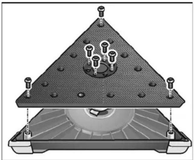
natural_image
Diagram of a mechanical assembly with a triangular base and internal components, no visible text or symbolsnatural_image
Technical illustration of a circular mechanical component with mounting base and internal mesh structure (no text or symbols)
natural_image
Mechanical assembly diagram showing a bolt inserted into a housing with a close-up view of the bolt head (no text or symbols present)Manager Research & Development (R & D)
Klaus Peter WeinperEckhard F Head of Quality Department (QD)
11.03.2019
text_image
Diagram showing mechanical assembly with numbered parts and directional arrows indicating motion or forcei INDICAÇÃO!
natural_image
Illustration of hands holding a circular object with a directional arrow, no text or symbols presentnatural_image
Close-up of a handheld electric shock absorber with labeled ports and motion indicator (no text or symbols on the device itself)text_image
Diagram illustrating a hand holding a car with a keypad and a magnified view showing the change in a control panel.text_image
1. "clic" 2.natural_image
Illustration of two hands using a handheld fuel pump against a diagonal line (no text or symbols)
ATENÇÃO!
natural_image
Illustration of a hand using a fuel pump to lift a vehicle, showing airflow direction (no text or symbols)natural_image
Illustration of hands using a tool to press or adjust a circular component on a mechanical device (no text or symbols visible)
text_image
7xnatural_image
Cross-sectional diagram of a mechanical component with embedded pins and mounting holes (no text or symbols)
natural_image
Technical illustration of a mechanical device with a central hub and textured base (no text or symbols)
natural_image
Diagram of a triangular structure with embedded bolts and a circular component, no text or symbols presentnatural_image
Technical illustration of a circular mechanical component with textured surface and two mounting points (no text or symbols)
natural_image
Mechanical assembly diagram showing a bolt inserted into a housing with a close-up view of the base (no text or symbols)Manager Research & Development (R & D)
Klaus Peter WeinperEckhard F Head of Quality Department (QD)
text_image
Diagram showing mechanical assembly with numbered components and directional arrows indicating motion or forcei LET OP
natural_image
Illustration of hands placing a circular object into a container with an arrow indicating rotation (no text or symbols)natural_image
Close-up of a mechanical device with a tool and cable, showing no visible text or symbols.text_image
Diagram illustrating a hand holding a power plug with a keypad and a magnified view showing the pad switch mechanism.text_image
1. "clic" 2.natural_image
Illustration of two hands using a handheld pump gun to lift a wall-mounted device (no text or symbols visible)
VOORZICHTIG!
natural_image
Illustration of a hand using a fuel pump to lift a vehicle, showing airflow direction (no text or symbols)natural_image
Illustration of hands operating a CD or DVD disc with a knob (no text or symbols visible)
text_image
7xnatural_image
Cross-sectional diagram of a speaker with internal components and mounting holes (no text or labels)
natural_image
Technical illustration of a mechanical device with a central hub and textured base (no text or symbols)
natural_image
Diagram of a mechanical assembly with a triangular base and internal components, no visible text or symbolsnatural_image
Technical illustration of a circular mechanical component with textured surface and two mounting points (no text or symbols)
natural_image
Mechanical assembly diagram showing a bolt and screw inserted into a housing (no text or symbols)text_image
Rikole B. D. 20-1Manager Research & Development (R & D)
Klaus Peter WeinperEckhard F Head of Quality Department (QD)
text_image
Diagram showing mechanical assembly with numbered components and directional arrows indicating motion or forcei BEMAERK
natural_image
Illustration of hands placing a circular object onto a mesh plate with an arrow indicating rotation (no text or symbols)natural_image
Close-up of a handheld electric shock absorber with labeled ports and an arrow indicating direction (no text or symbols on the device itself)Sluk af apparatet:
text_image
Diagram illustrating a hand holding a car with a keypad and a magnified view showing the change in control signals.natural_image
Illustration of two hands using a handheld pump gun to lift a wall-mounted device (no text or symbols visible)
FORSIGTIG!
natural_image
Illustration of a hand using a fuel pump to lift a vehicle, showing airflow direction (no text or symbols)natural_image
Illustration of hands operating a CD or DVD disc with a knob (no text or symbols visible)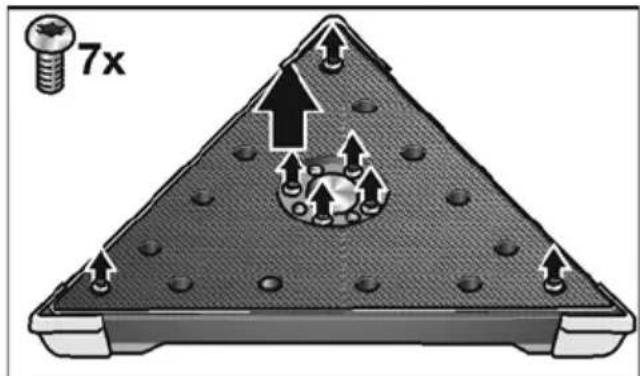
text_image
7xnatural_image
Cross-sectional diagram of a speaker with an integrated device, showing top and bottom views with no text or symbols.
natural_image
Technical illustration of a mechanical device with a central knob and textured base (no text or symbols)
natural_image
Cross-sectional diagram of a mechanical assembly with bolted components and a central circular component (no text or symbols)natural_image
Technical illustration of a circular mechanical component with internal mesh structure and mounting points (no text or symbols)
natural_image
Mechanical assembly diagram showing a bolt and screw on a base with an arrow indicating direction (no text or symbols)text_image
Zilie Bhat Q-1text_image
Technical diagram showing mechanical assembly with numbered components and directional arrows indicating motion or forcei HENVISNING
natural_image
Illustration of hands placing a circular object into a container with an arrow indicating rotation (no text or symbols)natural_image
Close-up of a handheld electric shaver with visible wiring and a black arrow indicating direction (no text or symbols)text_image
Diagram showing a hand holding a car with a keypad and plug, accompanied by an instructional arrow indicating rotation or change.text_image
1. "clic" 2.natural_image
Illustration of two hands using a handheld pump gun to lift a wall-mounted device (no text or symbols visible)
FORSIKTIG!
natural_image
Illustration of a hand using a fuel pump to lift a wall-mounted airfoil (no text or symbols present)natural_image
Illustration of hands operating a CD or DVD disc with a knob (no text or symbols visible)
text_image
7x■ Drei skruene mot urviseren, og ta dem av.
■ Borrelåsskivene kan tas av / fjernes.

natural_image
Cross-sectional diagram of a speaker with exposed components and screw holes (no text or labels)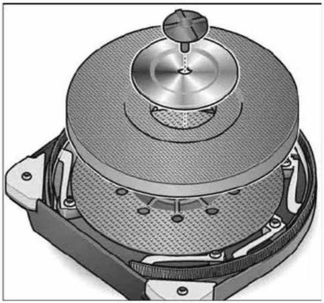
natural_image
Technical illustration of a mechanical device with a central knob and textured base (no text or symbols)
natural_image
Diagram of a mechanical assembly with a triangular base and internal components, no visible text or symbolsnatural_image
Technical illustration of a circular mechanical component with internal mesh structure and mounting points (no text or symbols)
natural_image
Mechanical assembly diagram showing a bolt inserted into a housing with a close-up view of the bolt head (no text or symbols present)■ De beskyttelseskantene som skal skiftes ut demonteres.
■ Nye beskyttelseskanter monteres.
I hjørnene bør det erfaringsmessig arbeides med mindre trykk, da det derved kan oppstå en større belastning på spissen av den trekantete slipetallerkenen.
text_image
Zilie Bhat Q-1Manager Research & Development (R & D)
Klaus Peter WeinperEckhard F Head of Quality Department (QD)
11.03.2019
text_image
Technical diagram showing mechanical assembly with numbered components and directional arrows indicating motion or movement.i OBS
natural_image
Illustration of hands placing a circular object into a container with an arrow indicating rotation (no text or symbols)natural_image
Close-up of a mechanical device with a probe inserted, showing no visible text or symbols.text_image
Diagram showing a hand holding a car with a keypad and plug, accompanied by an instructional arrow indicating rotation or change.text_image
1. "clic" 2.natural_image
Illustration of two hands using a handheld fuel pump against a plain background (no text or symbols)
VAR FÖRSIKTIG!
natural_image
Illustration of a hand using a fuel pump to lift a wall-mounted airfoil (no text or symbols present)natural_image
Illustration of hands operating a CD or DVD disc with a knob (no text or symbols visible)
text_image
7xnatural_image
Cross-sectional diagram of a mechanical component with embedded pins and mounting holes (no text or symbols)
natural_image
Technical illustration of a mechanical device with a central knob and textured base (no text or symbols)
natural_image
Diagram of a mechanical assembly with a triangular base and internal components, no visible text or symbolsnatural_image
Diagram of a circular mechanical component with internal mesh structure and two adjustment knobs (no text or symbols)
natural_image
Mechanical assembly diagram showing a bolt inserted into a hexagonal base, with no visible text or symbolstext_image
Zilie B. D. - rManager Research &
Development (R & D)
text_image
Technical diagram showing mechanical assembly with numbered components and directional arrows indicating motion or forcei OHJE
natural_image
Illustration of hands placing a circular object into a container with an arrow indicating rotation (no text or symbols)natural_image
Close-up of a mechanical device with a tool and cable, showing no visible text or symbols.Koneen pysäytys:
text_image
Diagram illustrating a hand holding an electric plug with a keypad and a magnified view showing the pad switch mechanism.text_image
1. "clic" 2.natural_image
Illustration of two hands using a handheld pump gun to lift a wall-mounted device (no text or symbols visible)
VARO!
natural_image
Illustration of a hand using a fuel pump to lift a wall-mounted airfoil (no text or symbols present)natural_image
Illustration of hands operating a CD or DVD disc with a knob (no text or symbols visible)
text_image
7xnatural_image
Cross-sectional diagram of a speaker with an integrated microphone and screw holes (no text or labels)
natural_image
Technical illustration of a mechanical device with a central hub and textured base (no text or symbols)
natural_image
Diagram of a mechanical assembly with a triangular base and internal components, no visible text or symbols■ Vaihda korvattavat ostat.
natural_image
Technical illustration of a circular mechanical component with internal mesh structure and mounting points (no text or symbols)
natural_image
Mechanical assembly diagram showing a bolt inserted into a housing with a close-up view of the bolt head (no text or symbols present)text_image
Zilie B. Box D.-rKlaus Peter WeinperEckhard F
Manager Research &
Head of Quality
Development (R & D)
Department (QD)
11.03.2019
text_image
Technical diagram of a spray gun with numbered parts and exploded views of the device's internal components.natural_image
Illustration of a hand holding a flexible hose with a hose being inserted, labeled "clic" (no text or symbols on the diagram itself)text_image
Diagram showing mechanical assembly steps with numbered labels and directional arrows indicating motion or movement.i УПОДЕІЕН
natural_image
Illustration of hands placing a circular object onto a mesh plate with an arrow indicating rotation (no text or symbols)natural_image
Close-up of a handheld electric shock absorber with labeled ports and motion indicator (no text or symbols on device body)text_image
Diagram illustrating a hand holding an electric plug with a keypad and a magnified view showing the pad switch mechanism.natural_image
Illustration of two hands using a handheld pump gun to lift a wall-mounted device (no text or symbols visible)
ΠΡΟΣΟΧΗ!
natural_image
Illustration of a hand using a fuel pump to lift a wall, showing mechanical components and airflow direction (no text or symbols)natural_image
Illustration of hands operating a CD or DVD disc with a knob (no text or symbols visible)
text_image
7xnatural_image
Cross-sectional diagram of a speaker with an integrated device, showing top and bottom views with no text or symbols.
natural_image
Technical illustration of a mechanical device with a central knob and textured base (no text or symbols)
natural_image
Diagram of a mechanical assembly with a triangular base and internal components, no visible text or symbolsnatural_image
Technical illustration of a circular mechanical component with textured surface and mounting points (no text or symbols)
natural_image
Mechanical assembly diagram showing a bolt inserted into a housing component, with no visible text or symbolstext_image
Zilule B. R. D.Manager Research & Development (R & D)
Klaus Peter WeinperEckhard F Head of Quality Department (QD)
natural_image
Illustration of a hand holding a cable with a connector, labeled "clic" (no text or symbols on the diagram itself)text_image
Technical diagram showing mechanical assembly with numbered components and directional arrows indicating motion or forcei BilGi
natural_image
Illustration of hands pressing down on a circular object with an arrow indicating motion (no text or symbols)natural_image
Close-up of a handheld electric shock absorber with labeled ports and an arrow indicating motion (no text or symbols present)text_image
Diagram illustrating a hand holding a car with a keypad and a magnified view showing a change in the phone's price.natural_image
Illustration of two hands using a handheld pump gun to lift a wall-mounted device (no text or symbols visible)
DİKKAT!
natural_image
Illustration of a hand using a fuel pump to lift a wall-mounted airfoil (no text or symbols present)natural_image
Close-up of hands operating a CD or DVD disc with a knob, no visible text or symbols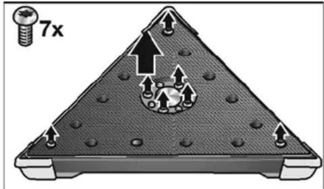
text_image
7xnatural_image
Illustration of a speaker emitting sound waves into a circular base, showing no text or symbols.
natural_image
Technical illustration of a mechanical device with a central knob and textured base (no text or symbols)
natural_image
Diagram of a triangular structure with embedded components and mounting points, no visible text or symbolsnatural_image
Technical illustration of a circular mechanical component with textured surface and mounting base (no text or symbols)
natural_image
Mechanical assembly diagram showing a bolt and screw inserted into a housing (no text or symbols)Manager Research & Development (R & D)
Klaus Peter WeinperEckhard F Head of Quality Department (QD)
text_image
Diagram of a mechanical device with numbered parts and directional arrows indicating motion or assembly.i WSKAZÓWKA
natural_image
Illustration of hands placing a circular object onto a mesh plate with an arrow indicating rotation (no text or symbols)natural_image
Close-up of a handheld electric shaver with labeled ports and an arrow indicating direction (no text or symbols present)text_image
Diagram showing a hand holding a tool with a control panel labeled 2, 3, 4 and an inset illustrating the process with arrows and a cross.text_image
1. "clic" 2.natural_image
Illustration of two hands using a handheld pump gun to lift a wall-mounted device (no text or symbols visible)
OSTROŻNIE!
natural_image
Illustration of a hand using a fuel pump to lift a wall-mounted airfoil (no text or symbols present)natural_image
Illustration of hands operating a CD or DVD disc with a knob (no text or symbols visible)
text_image
7xnatural_image
Cross-sectional diagram of a mechanical component with internal parts and mounting holes (no text or symbols)
natural_image
Technical illustration of a mechanical device with a central knob and textured base (no text or symbols)
natural_image
Diagram of a mechanical assembly with a triangular base and internal components, no visible text or symbolsnatural_image
Technical illustration of a circular mechanical component with internal mesh structure and mounting points (no text or symbols)
natural_image
Mechanical assembly diagram showing a component with a bolt and pin inserted into a base, alongside its close-up view (no text or symbols)text_image
Handwritten signature or scribble with partial text and a curved line, likely from a document or form.Manager Research & Development (R & D)
Klaus Peter WeinperEckhard F
Head of Quality Department (QD)
11.03.2019
text_image
Diagram of a mechanical assembly with numbered parts and directional arrows indicating motion or forcei MEGJEGYZÉS
natural_image
Illustration of hands placing a circular object onto a mesh plate with an arrow indicating rotation (no text or symbols)natural_image
Close-up of a handheld electric shock absorber with visible internal components and a black arrow indicating direction (no text or symbols)A gép kikapcsolása
text_image
Diagram illustrating a hand holding a car with a keypad and a magnified view showing the change in control buttons.text_image
1. "clic" 2.natural_image
Illustration of two hands using a handheld fuel pump against a plain background (no text or symbols)
VIGYÁZAT!
natural_image
Illustration of a hand using a fuel pump to lift a wall-mounted airfoil (no text or symbols present)natural_image
Illustration of hands using a tool to press or adjust a circular component on a disc (no text or symbols visible)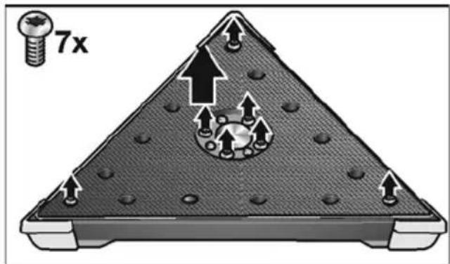
text_image
7xnatural_image
Cross-sectional diagram of a speaker with an integrated device, showing top and bottom views with no text or symbols.
natural_image
Technical illustration of a mechanical device with a central hub and textured base (no text or symbols)
natural_image
Diagram of a triangular structure with embedded bolts and a circular component, no text or symbols presentnatural_image
Technical illustration of a circular mechanical component with internal mesh structure and mounting points (no text or symbols)
natural_image
Mechanical assembly diagram showing a bolt inserted into a housing component, with no visible text or symbolsManager Research & Development (R & D)
Klaus Peter WeinperEckhard F Head of Quality Department (QD)
11.03.2019
text_image
Diagram showing mechanical assembly with numbered components and directional arrows indicating motion or forcei UPOZORNĚNÍ
natural_image
Illustration of hands holding a circular object with a black arrow indicating direction (no text or symbols)natural_image
Close-up of a mechanical device with a circular arrow and directional indicator (no text or symbols)Vypnutí nářadí:
text_image
Diagram showing a hand holding an electric plug with a keypad and a magnified inset highlighting the switch mechanism.natural_image
Illustration of two hands using a handheld pump gun to lift a wall-mounted device (no text or symbols visible)
POZOR!
natural_image
Illustration of a hand using a fuel pump to lift a wall, showing mechanical components and airflow direction (no text or symbols)natural_image
Illustration of hands using a tool to press or adjust a CD or DVD disc component (no text or symbols visible)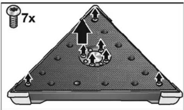
text_image
7xnatural_image
Cross-sectional diagram of a speaker with an integrated device, showing top and bottom views with no text or symbols.
natural_image
Technical illustration of a mechanical device with a central knob and textured base (no text or symbols)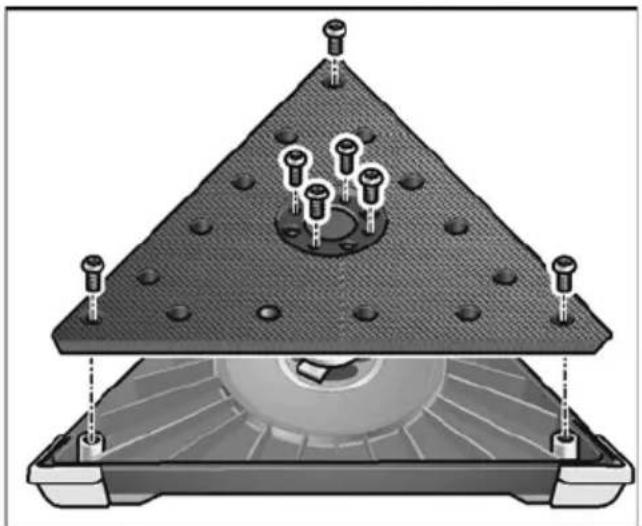
natural_image
Diagram of a mechanical assembly with a triangular base and internal components, no visible text or symbolsnatural_image
Diagram of a circular mechanical component with internal mesh structure and two adjustment knobs (no text or symbols)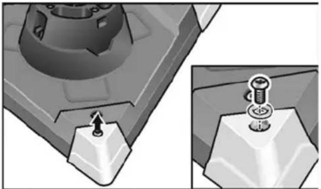
natural_image
Mechanical assembly diagram showing a bolt inserted into a housing with a close-up view of the bolt head (no text or symbols present)text_image
R. H. L. B. R. R.Klaus Peter WeinperEckhard F
Manager Research & Development (R & D)
Head of Quality Department (QD)
11.03.2019
text_image
Diagram of a mechanical device with numbered parts and directional arrows indicating motion or assembly.i UPOZORNENIE
natural_image
Illustration of hands placing a circular object onto a mesh plate with an arrow indicating rotation (no text or symbols)natural_image
Close-up of a handheld electric shock absorber with labeled ports and an arrow indicating force (no text or symbols present)Vypnutie náradia:
text_image
Diagram showing a hand holding an electric plug with a keypad and a magnified view of the device's internal mechanism.natural_image
Illustration of two hands using a handheld fuel pump against a wall (no text or symbols)
POZOR!
natural_image
Illustration of a hand using a fuel pump to lift a vehicle, showing airflow direction (no text or symbols)natural_image
Illustration of hands operating a mechanical component with a knob (no text or symbols visible)
text_image
7xnatural_image
Cross-sectional diagram of a mechanical component with embedded pins and mounting holes (no text or symbols)
natural_image
Cross-sectional diagram of a mechanical device with a central knob and textured base (no text or symbols)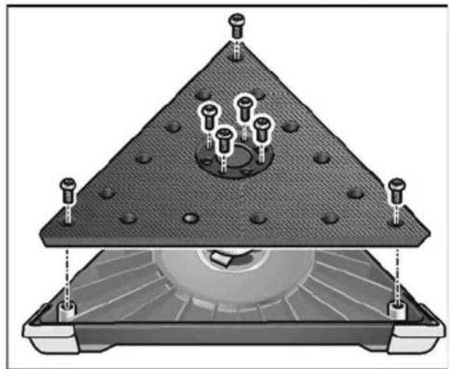
natural_image
Cross-sectional diagram of a mechanical assembly with bolted components and a central circular component (no text or labels)natural_image
Technical illustration of a circular mechanical component with internal mesh structure and mounting points (no text or symbols)
natural_image
Mechanical assembly diagram showing a bolt inserted into a component, with no visible text or symbolsManager Research & Development (R & D)
text_image
Technical diagram showing mechanical assembly with numbered components and directional arrows indicating motion or forcei NAPUTAK
Pričvršćivanje/zamjena trokutaste i ekscentarske brusne glave vrši se na isti način.
Uporaba usisivača
OPREZ!
natural_image
Illustration of hands holding a circular object with a black arrow indicating rotation (no text or symbols)■ Položite brusni list centrirano na disk za brusni list i pritisnite.
■ Za provjeru centričnog opterećenja sredstva za brušenje provedite probni rad.
OPREZ!
Disk za brusni papir nikada ne koristite kao sredstvo za brušenje. Zidnu brusilicu nikada ne koristite bez brusnog lista, kako biste izbjegli jako oštećenje radne površine!
natural_image
Close-up of a handheld electric shock absorber with labeled ports and an arrow indicating motion (no text or symbols present)text_image
Diagram illustrating a hand holding a car with a keypad and cable, showing a directional change with arrows and a plus sign.Radi namještanja radnog broja okretaja kotač za namještanje postaviti na željenu vrijednost.
Upotrebljavajte produžetak (opcionalno)
Za zidnu brusilicu GE 7 dostupan je produžetak. S produžnom cijevi može se povećati doseg prilikom rada sa zidnom brusilicom.
text_image
1. "clic" 2.natural_image
Illustration of two hands using a handheld pump gun to lift a wall-mounted device (no text or symbols visible)
OPREZ!
Rotirajući dijelovi na brusnoj glavi ne smiju doći u kontakt s oštrim, isturenim predmetima (npr. čavlima vijcima, razvodnim kutijama). Takav kontakt s isturenim predmetima mogao bi oštetiti disk za brusni papir.
Oštećen ili jako istrošen disk za brusni papir može se zamijeniti (pogledajte poglavlje „Održavanje i njega“).
Upute za rad
Vijenac četke
natural_image
Illustration of a hand using a fuel pump to lift a vehicle, showing airflow direction (no text or symbols)Budući da je trokutasta brusna glava zakretljiva, možete brusiti sve do kutova zida/stropa.
Održavanje i njega

POZOR!
natural_image
Illustration of hands operating a mechanical disc component with a knob (no text or symbols visible)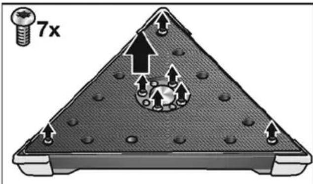
text_image
7xnatural_image
Cross-sectional diagram of a speaker with an integrated device, showing top and bottom views with no text or symbols.
natural_image
Technical illustration of a mechanical device with a central knob and textured base (no text or symbols)
natural_image
Diagram of a mechanical assembly with a triangular base and internal components, no visible text or symbolsnatural_image
Technical illustration of a circular mechanical component with internal mesh structure and mounting points (no text or symbols)
natural_image
Mechanical assembly diagram showing a bolt and nut assembly with two views (no text or symbols)■ Demontirajte kutnike koje treba zamijeniti.
■ Montirajte nove kutnike.
U kutovima bi trebalo raditi manjom silom pritiskanja na temelju iskustva jer dolazi do većeg opterećenja vrhova trokutastog brusnog tanjura.
Kutnici trokutaste brusne glave mogu se lako zamijeniti ako su jako istrošeni.
Popravci
Manager Research & Development (R & D)
Klaus Peter WeinperEckhard Rühle Head of Quality Department (QD)
Hrup in tresljaji 244
Pregled 245
natural_image
Illustration of hands placing a circular object into a container with an arrow indicating rotation (no text or symbols)natural_image
Close-up of a handheld electric shock absorber with labeled ports and an arrow indicating direction (no text or symbols on the device itself)Izklop orodja:
■ Na kratko pritisnite stikalo.
text_image
Diagram showing a hand holding a power tool with a keypad and a magnified inset highlighting the control panel.text_image
1. "clic" 2.natural_image
Illustration of two hands using a handheld fuel pump against a plain background (no text or symbols)
POZOR!
natural_image
Illustration of a hand using a fuel pump to lift a wall-mounted airfoil (no text or symbols present)natural_image
Close-up of hands operating a CD or DVD disc with a knob (no text or symbols visible)
text_image
7xnatural_image
Cross-sectional diagram of a mechanical component with embedded pins and mounting holes (no text or symbols)
natural_image
Technical illustration of a mechanical device with a central hub and textured base (no text or symbols)
natural_image
Cross-sectional diagram of a mechanical assembly with bolted components and a central circular component (no text or symbols)■ Zamenjajte dele, ki jih želite zamenjati.
■ Brusilno glavo sestavite v obratnem vrstnem redu.
Menjava krtačnega venca
natural_image
Technical illustration of a circular mechanical component with internal mesh structure and mounting points (no text or symbols)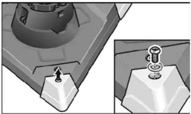
natural_image
Mechanical assembly diagram showing a bolt inserted into a housing with a close-up view of the screw base (no text or symbols present)Manager Research & Development (R & D)
Klaus Peter WeinperEckhard Rühle Head of Quality Department (QD)
text_image
Diagram showing mechanical assembly steps with numbered labels indicating different states or components.i INDICATIE
natural_image
Illustration of hands placing a circular object onto a mesh plate with an arrow indicating rotation (no text or symbols)natural_image
Close-up of a mechanical device with a tool handle and cable, showing no visible text or symbols.text_image
Diagram illustrating the use of a power plug to remove a battery, with an inset showing the battery being removed.text_image
1. "clic" 2.natural_image
Illustration of two hands using a handheld fuel pump against a plain wall (no text or symbols)PRECAUTIE!
natural_image
Illustration of a hand using a fuel pump to lift a vehicle, showing motion and safety (no text or symbols)natural_image
Close-up of hands operating a CD or DVD disc with a knob (no text or symbols visible)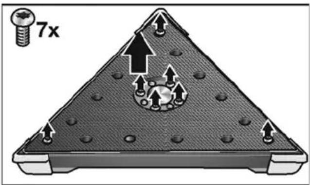
text_image
7xnatural_image
Cross-sectional diagram of a speaker with exposed circuit board and screw holes (no text or labels)
natural_image
Technical illustration of a mechanical device with a central knob and textured base (no text or symbols)
natural_image
Cross-sectional diagram of a mechanical assembly with bolted components and a central circular component (no text or symbols)natural_image
Technical illustration of a circular mechanical component with internal mesh structure and mounting points (no text or symbols)
natural_image
Mechanical assembly diagram showing a bolt and screw inserted into a housing (no text or symbols)EN 60745 conform prevederilor Directivei 2014/30/UE, 2006/42/CE, 2011/65/UE.
Responsabili pentru documente tehnice: FLEX-Elektrowerkzeuge GmbH, R & D Bahnhofstrasse 15, D-71711 Steinheim/Murr

text_image
Rille B B -1Manager Research & Development (R & D)
Klaus Peter WeinperEckhard F Head of Quality Department (QD)
11.03.2019
text_image
Diagram showing mechanical assembly with numbered components and directional arrows indicating motion or forcei УКАЗАНИЕ!
natural_image
Illustration of a hand pressing down on a circular object with an arrow indicating motion (no text or symbols)natural_image
Close-up of a mechanical device with a tool and cable, showing no visible text or symbols.text_image
Diagram showing a hand holding a power plug with a control panel labeled 2, 3, and 4, alongside an inset illustrating the process of adjusting a device.text_image
1. "clic" 2.text_image
Diagram of a handheld tool with labeled parts and directional arrows indicating movement or assembly.natural_image
Illustration of two hands using a handheld pump gun to lift a wall-mounted device (no text or symbols visible)
ВНИМАНИЕ!
natural_image
Illustration of a hand using a fuel pump to lift a vehicle, showing airflow direction (no text or symbols)natural_image
Illustration of hands operating a CD or DVD disc with a knob (no text or symbols visible)
text_image
7xnatural_image
Cross-sectional diagram of a mechanical component with embedded pins and mounting holes (no text or symbols)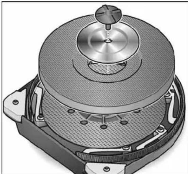
natural_image
Cross-sectional diagram of a mechanical device with a central hub and internal components (no text or symbols visible)
natural_image
Diagram of a triangular structure with embedded components and mounting points (no text or symbols)natural_image
Technical illustration of a circular mechanical component with textured surface and mounting points (no text or symbols)
natural_image
Mechanical component diagram showing a base with a knob and a pin inserted, alongside its 3D view (no text or symbols)text_image
B. F. - 1Manager Research & Development (R & D)
text_image
Technical diagram showing mechanical assembly with numbered components and directional arrows indicating motion or movement.i ПРИМЕЧАНИЕ
natural_image
Illustration of hands holding a circular object with a black arrow indicating rotation (no text or symbols)natural_image
Close-up of a handheld electric shock absorber with labeled ports and an arrow indicating motion (no text or symbols present)Выключение прибора:
text_image
Diagram illustrating a hand tool with a control panel labeled '2', showing a directional arrow and a cross symbol.text_image
1. "clic" 2.text_image
Diagram of a handheld electric shaver with labeled parts and directional arrows indicating motion or movement.natural_image
Illustration of two hands using a handheld fuel pump against a wall (no text or symbols)
ВНИМАНИЕ!
natural_image
Illustration of a hand using a fuel pump to lift a wall-mounted device (no text or symbols visible)natural_image
Illustration of hands operating a CD or DVD disc with a knob (no text or symbols visible)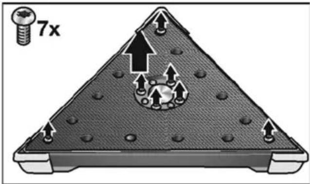
text_image
7xnatural_image
Illustration of a speaker with a perforated head and internal components, no text or symbols present
natural_image
Technical illustration of a mechanical device with a central hub and textured base (no text or symbols)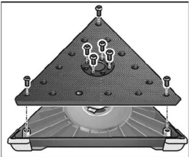
natural_image
Cross-sectional diagram of a mechanical assembly with a triangular base and internal components (no text or symbols)natural_image
Technical illustration of a circular mechanical component with internal mesh structure and mounting points (no text or symbols)
natural_image
Mechanical assembly diagram showing a bolt inserted into a housing component, with an inset view of the same component (no text or symbols present)Manager Research & Development (R & D)
Klaus Peter WeinperEckhard F
Head of Quality Department (QD)
11.03.2019
text_image
Technical diagram of a spray gun with numbered parts and exploded views of the component layout1 L i h v i m i s p e kinnise rōngasharjaga
2 Kardaanligend
natural_image
Illustration of a hand holding a flexible hose with a cord, emitting a 'click' button (no text or symbols on the diagram itself)text_image
Diagram showing mechanical assembly with numbered components and directional arrows indicating motion or forcei MÄRKUS
natural_image
Illustration of hands placing a circular object onto a mesh plate with an arrow indicating rotation (no text or symbols)natural_image
Close-up of a handheld electric shaver with a circular arrow indicator (no text or symbols on the device itself)text_image
Diagram showing a hand holding a power plug with a keypad and a magnified view of the device's internal mechanism.text_image
1. "clic" 2.natural_image
Illustration of two hands using a handheld fuel pump against a plain background (no text or symbols)
ETTEVAATUST!
Lihvimispea pöörlevad osad ei tohi minna vastu teravaid, esileulatuvaid esemeid (nt naelad, kruvid, elektrikarbid).
natural_image
Illustration of a hand using a fuel pump to lift a wall, showing mechanical components and airflow direction (no text or symbols)natural_image
Illustration of hands operating a CD or DVD disc with a knob (no text or symbols visible)
text_image
7xnatural_image
Cross-sectional diagram of a mechanical device with internal components and mounting holes (no text or symbols)
natural_image
Technical illustration of a mechanical device with a central hub and textured base (no text or symbols)
natural_image
Diagram of a mechanical assembly with a triangular base and internal components, no visible text or symbolsnatural_image
Cross-sectional diagram of a circular mechanical component with internal mesh structure and mounting points (no text or symbols)
natural_image
Mechanical assembly diagram showing a bolt inserted into a hexagonal base, with no visible text or symbolsManager Research & Development (R & D)
Klaus Peter WeinperEckhard Rühle Head of Quality Department (QD)
11.03.2019
text_image
Diagram of a mechanical device with numbered parts and directional arrows indicating motion or assembly.i NURODYMAS
natural_image
Illustration of hands holding a circular object with a curved arrow indicating rotation (no text or symbols)natural_image
Close-up of a handheld electric shock absorber with labeled ports and directional arrow (no text or symbols beyond basic diagram)text_image
Diagram illustrating a hand holding an electric plug with a keypad and a magnified view showing the pad switch mechanism.natural_image
Illustration of two hands using a handheld pump gun to lift a wall-mounted device (no text or symbols visible)
ATSARGIA!!
natural_image
Illustration of a hand using a fuel pump to lift a wall-mounted airfoil (no text or symbols present)natural_image
Illustration of hands operating a CD or DVD disc with a knob (no text or symbols visible)
text_image
7xnatural_image
Cross-sectional diagram of a speaker with internal components and mounting holes (no text or labels)
natural_image
Technical illustration of a mechanical device with a central hub and textured base (no text or symbols)
natural_image
Cross-sectional diagram of a mechanical assembly with a triangular base and internal components (no text or symbols)natural_image
Technical illustration of a circular mechanical component with textured surface and mounting points (no text or symbols)
natural_image
Mechanical assembly diagram showing a bolt and screw inserted into a block, with no visible text or symbolstext_image
Rille B. D. 2-1Manager Research & Development (R & D)
Klaus Peter WeinperEckhard F Head of Quality Department (QD)
11.03.2019
text_image
Diagram of a mechanical assembly with numbered parts and directional arrows indicating motion or forcei NORĀDĪJUMS!
natural_image
Illustration of hands holding a circular object with a black arrow indicating rotation (no text or symbols)natural_image
Close-up of a handheld electric shock absorber with labeled ports and directional arrow (no text or symbols beyond basic diagram)Ierīces izslēgšana:
■ Īsi nospiediet slēdzi.
text_image
Diagram showing a hand holding a car with a calculator and a magnified view of its function, including an '×' symbol.text_image
1. "clic" 2.natural_image
Illustration of two hands using a handheld fuel pump against a plain background (no text or symbols)
UZMANĪBU!
natural_image
Illustration of a hand using a fuel pump to lift a vehicle, showing motion and safety (no text or symbols)natural_image
Illustration of hands operating a CD or DVD disc with a knob (no text or symbols visible)
text_image
7xnatural_image
Cross-sectional diagram of a mechanical component with embedded pins and mounting holes (no text or symbols)
natural_image
Technical illustration of a mechanical device with a central hub and textured base (no text or symbols)
natural_image
Cross-sectional diagram of a mechanical assembly with bolt holes and a triangular base (no text or symbols)natural_image
Technical illustration of a circular mechanical component with textured surface and mounting base (no text or symbols)
natural_image
Mechanical assembly diagram showing a bolt inserted into a block, with no visible text or symbolstext_image
Zilie B. D. - rKlaus Peter WeinperEckhard F
Manager Research & Development (R & D)
Head of Quality Department (QD)
11.03.2019
natural_image
Technical illustration of a circular mechanical component with internal mesh structure and mounting points (no text or symbols)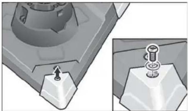
natural_image
Mechanical component diagram showing a bolt and nut assembly with a pin inserted (no text or symbols)natural_image
Cross-sectional diagram of a speaker or audio device showing top and bottom views with no visible text or symbols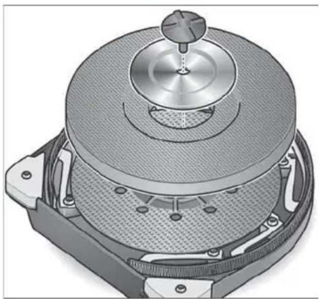
natural_image
Technical illustration of a mechanical device with a central hub and textured base (no text or symbols)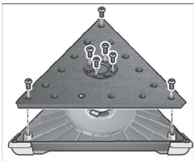
natural_image
Diagram of a triangular structure with embedded components and mounting points (no text or symbols)الصيانة والعنابة
خذیر!

natural_image
Close-up of hands using a tool to press or adjust a mechanical component on a circular base (no text or symbols visible)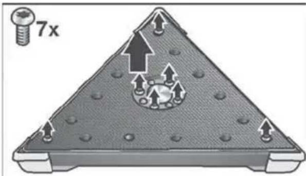
text_image
7xnatural_image
Illustration of a hand holding a fuel nozzle with arrows indicating airflow direction (no text or symbols)natural_image
Illustration of two hands using a handheld pump gun to lift a person's arm (no text or symbols visible)احترس!

text_image
Diagram illustrating a hand holding a device with labeled parts and directional arrows, including a magnified view of the device's internal structure.natural_image
Illustration of hands placing a circular component into a mesh plate with an arrow indicating rotation (no text or symbols)natural_image
Close-up of a handheld electric shock absorber with labeled ports and a directional arrow (no text or symbols beyond basic diagram)text_image
Diagram showing mechanical assembly steps with numbered labels indicating different states or components.تنييه!
i
text_image
Labeled diagram of a cleaning tool with numbered parts including a hand, hose, and clamp