RS LED D1 - Lighting STEINEL - Free user manual and instructions
Find the device manual for free RS LED D1 STEINEL in PDF.
| Product type | Indoor luminaire with HF motion detector |
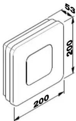
| Dimensions (H × W × D) | 200 × 200 × 53 mm |
| Power supply | 220–240 V, 50/60 Hz |
| Power consumption (Pon) | 8.80 W |
| Luminous flux | 759 lm |
| Color temperature | 3,000 K (warm white) |
| Color rendering index (CRI) | 83 |
| Average lifespan | >60,000 h (L70B50 at 25 °C) |
| Detection angle | 360° with 160° angular opening |
| Detector range | ∅ 3–8 m |
| Time delay | From 5 s to 15 min |
| Trigger threshold | From 2 to 2,000 lx |
| Orientation lighting | 10% of rated power |
| Protection rating | IP20 |
| Protection class | II |
| Energy efficiency class | F |
| Detection technology | HF 5.8 GHz (temperature-stabilized) |
| HF transmission power | ~1 mW |
| Main functions | Motion detection, forced lighting, orientation lighting |
| Scope of delivery | Luminaire, 3 screws, 3 wall plugs, 3 spacer pieces |
| Settings | Time delay, range, trigger threshold, orientation lighting |
| Safety | Disconnect power before maintenance; installation according to standard NF C-15100 |
| Maintenance | The light source cannot be replaced; replace the entire unit if defective |
| Manufacturer's warranty | 36 months from date of purchase |
Frequently Asked Questions - RS LED D1 STEINEL
User questions about RS LED D1 STEINEL
0 question about this device. Answer the ones you know or ask your own.
Ask a new question about this device
Download the instructions for your Lighting in PDF format for free! Find your manual RS LED D1 - STEINEL and take your electronic device back in hand. On this page are published all the documents necessary for the use of your device. RS LED D1 by STEINEL.
USER MANUAL RS LED D1 STEINEL
25, Manasty Road · Axis Park
Orton Southgate
GB-Peterborough Cambs PE2 6UP
Tel.: +44/1733/366-700
steinel@steinel.co.uk
IE Socket Tool Company Ltd
Unit 714 Northwest Business Park
Kilshane Drive · Ballycoolin · Dublin 15
info@tashev-galving.com
www.tashev-galving.com
RU REAL.Electro
109029, Москва
ул. Средняя
No. 828-838 Zhangyang Road
200122 Shanghai, PR China
Tel: +86 21 5820 4486
Fax: +86 21 5820 4212
www.steinel.cn
info@steinel.cn

.steinel
natural_image
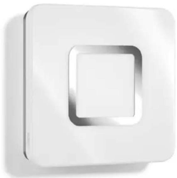
White square wall-mounted device with a recessed square cutout (no text or symbols visible)RS LED M1

DE....5 Textteil beachten!
GB .....10 Follow written instructions!
FR....14 Suivre les instructions ci-après!
NL....18 Gebruiksaanwijzing opvolgen!
IT.....22 Leggere attentamente le istruzioni!
ES....26 ¡Obsérvese la información textual!
PT....30 Siga as instruções escritas
SE....34 Följ den skriftliga montageinstruktionen.
DK....38 Følg de skriftlige instruktioner!
Fl. 42 Huomioi tekstiosa!
NO .....46 Se tekstdelen!
GR .....50 Τηρείτε γραπτές οδηγίες!
TR....54 Yazılı talimatlara uyunuz!
HU .....58 A szöveges utasításokat tartsa be!
CZ....62 Dodržujte písemné pokyny!
SK....66 Dodržiavajte písomné informácie!
PL....70 Postępować zgodnie z instrukcją!
RO .....74 Respectați instrucțiunile următoare!
SI .....78 Upoštevajte besedilo!
HR.....82 Pridržavajte se uputa!
EE....86 Järgige tekstiosa!
LT .....90 Atsižvelgti j rašytines instrukcijas!
LV....94 Pievērsiet uzmanību teksta daļai!
RU.....98 Соблюдать текстовую инструкцию!
BG .....102 Прочетете инструкциите!
CN .....106 遵守文字说明要求!
3.1
natural_image
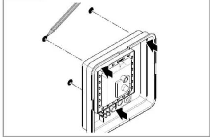
Technical illustration of a door panel and four screw fasteners (no text or symbols)3.2
text_image
53 200 2003.3
natural_image
Isometric view of a rectangular electronic component with a square cutout and labeled point A (no text or symbols beyond label)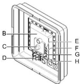
text_image
B C D E F G H3.4
text_image
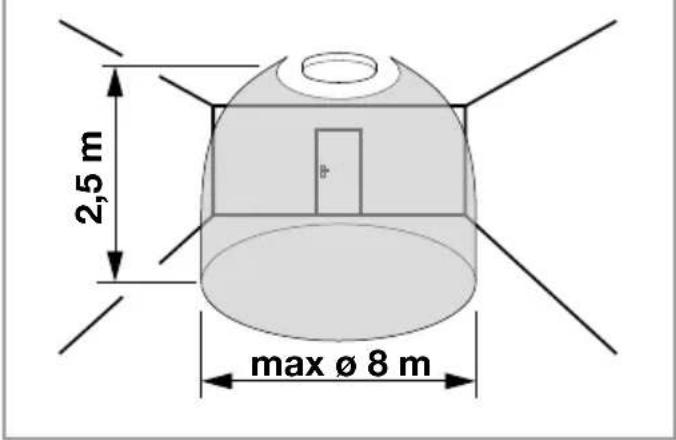
2,5 m max Ø 8 m5.1
natural_image
Technical line drawing of a device casing with internal components and directional arrows indicating assembly (no text or symbols)3.5
text_image
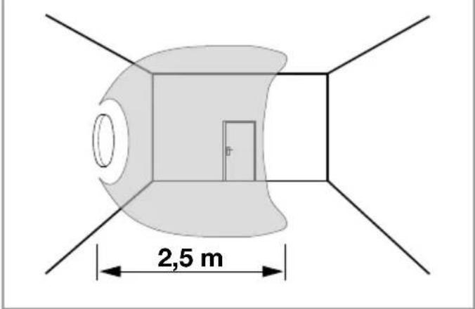
2,5 m5.2
natural_image
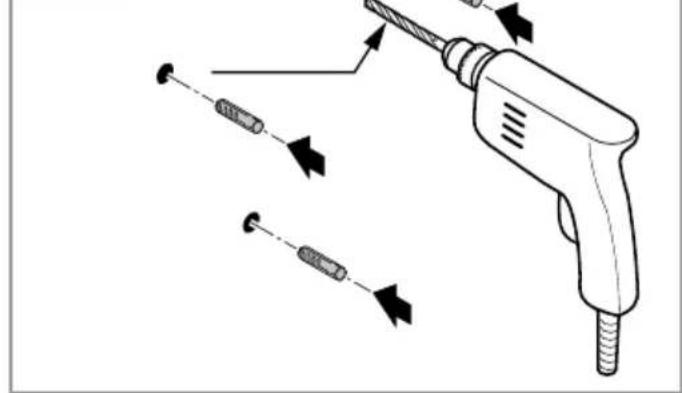
Illustration of a soldering iron with multiple screw tips and a handle, showing mechanical assembly (no text or symbols)3.6
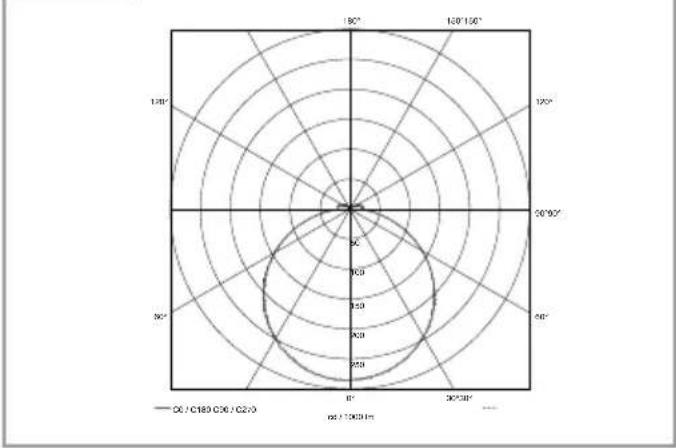
radar
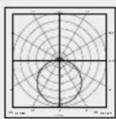
| Angle | Value | |-------|-------| | 0° | 180 | | 30° | 150 | | 60° | 120 | | 90° | 80 | | 120° | 40 | | 150° | 20 | | 180° | 10 | | 210° | 5 | | 240° | 3 | | 270° | 2 | | 300° | 1 | | 330° | 0.5 | | 360° | 0.2 |5.3
text_image
Technical diagram showing installation of a device with labeled components and directional arrows indicating assembly or movement.4.1
text_image
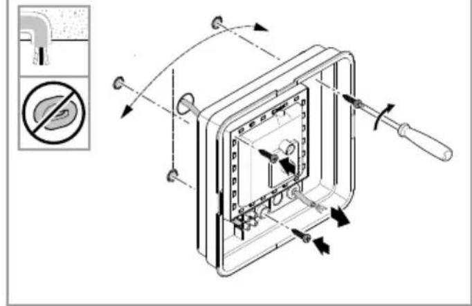
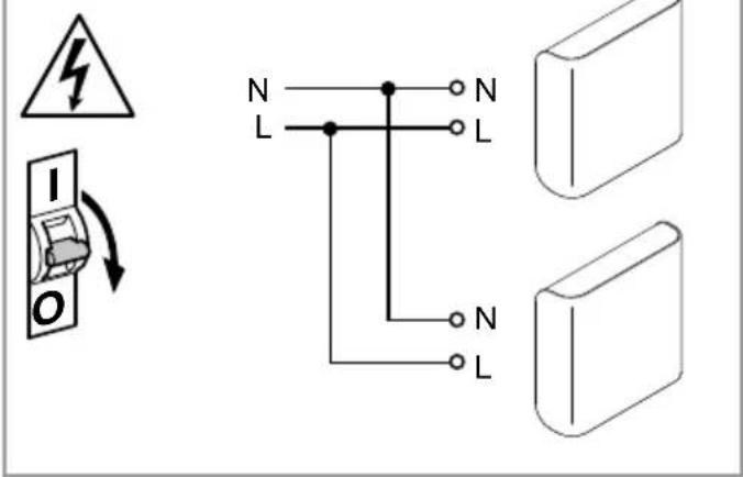
Electrical circuit diagram showing a fuse, normally open switch, and two terminal blocks with labeled wires (N, L) and grounding symbols.5.4
text_image
Technical diagram of a device with labeled components and directional arrows indicating assembly or movement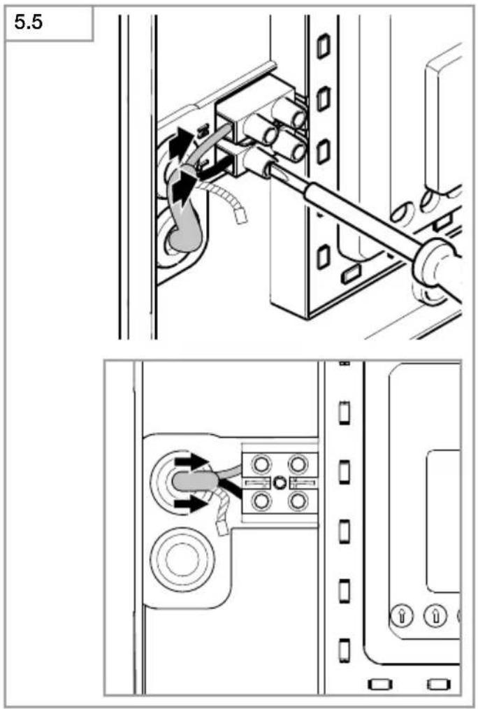
text_image
5.5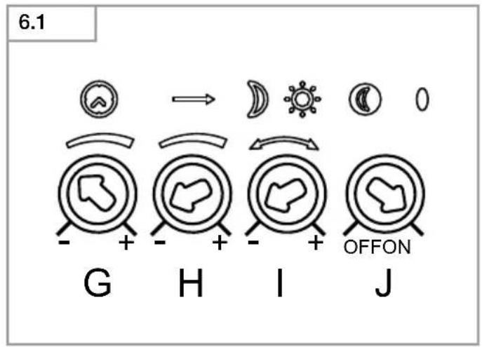
text_image
6.1 G H I J OFFON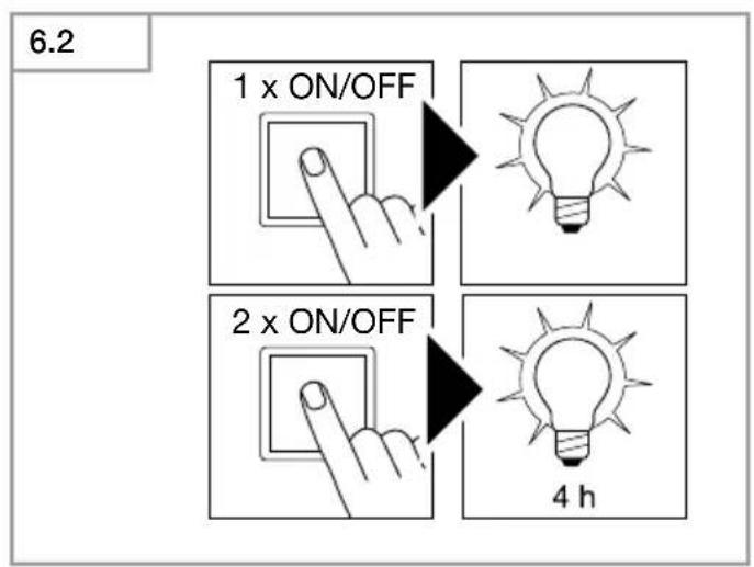
text_image
6.2 1 x ON/OFF 2 x ON/OFF 4 h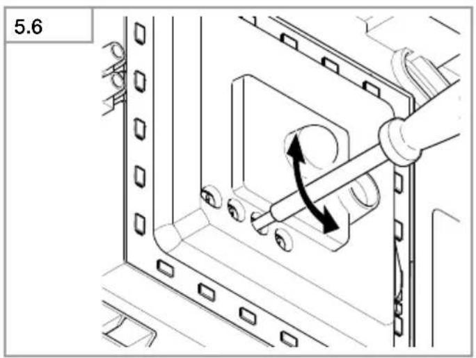
natural_image
Technical diagram of a mechanical assembly with directional arrows indicating motion (no text or symbols)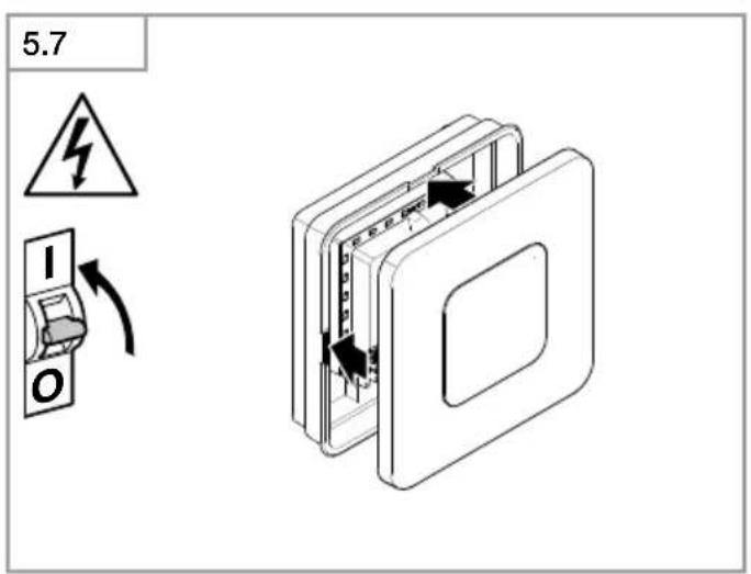
text_image
5.7 I ODE
Please read carefully and keep in a safe place.
- Under copyright. Reproduction either in whole or in part only with our consent.
-Subject to change in the interest of technical progress.
Symbols

Hazard warning!

Reference to other information in the document.
2. General safety precautions

Disconnect the power supply before attempting any work on the unit.
- During installation, the electric power cable being connected must not be live. Therefore, switch off the power first and use a voltage tester to make sure the wiring is off-circuit.
- Installing the sensor-switched light involves work on the mains supply voltage. This work must therefore be carried out professionally in accordance with national wiring regulations and electrical operating conditions. (e.g.: DE: VDE 0100, ATÖVE / ÖNORM E8001-1, CH: SEV 1000)
- Only use genuine replacement parts.
• Repairs may only be made by specialist workshops.
3. RS LED M1
Proper use
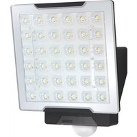
- Sensor-switched indoor light with active motion detector for installing indoors.
The integrated HF sensor emits high-frequency electromagnetic waves (5.8 GHz) and receives their echo. The change in echo caused by the slightest movement within the detection zone of the light is detected by the sensor. A microprocessor then issues the switch command "switch light ON". Detection is possible through doors, panes of glass or thin walls.
Note:
The high-frequency power of the HF sensor is approx. 1 mW – that is 1000 times less than the transmission power of a mobile phone or microwave oven.
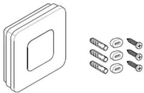
Package contents M1 (Fig. 3.1)
Sensor-switched light
3 screws
3 wall plugs
3 spacers
Product dimensions M1 (Fig. 3.2)
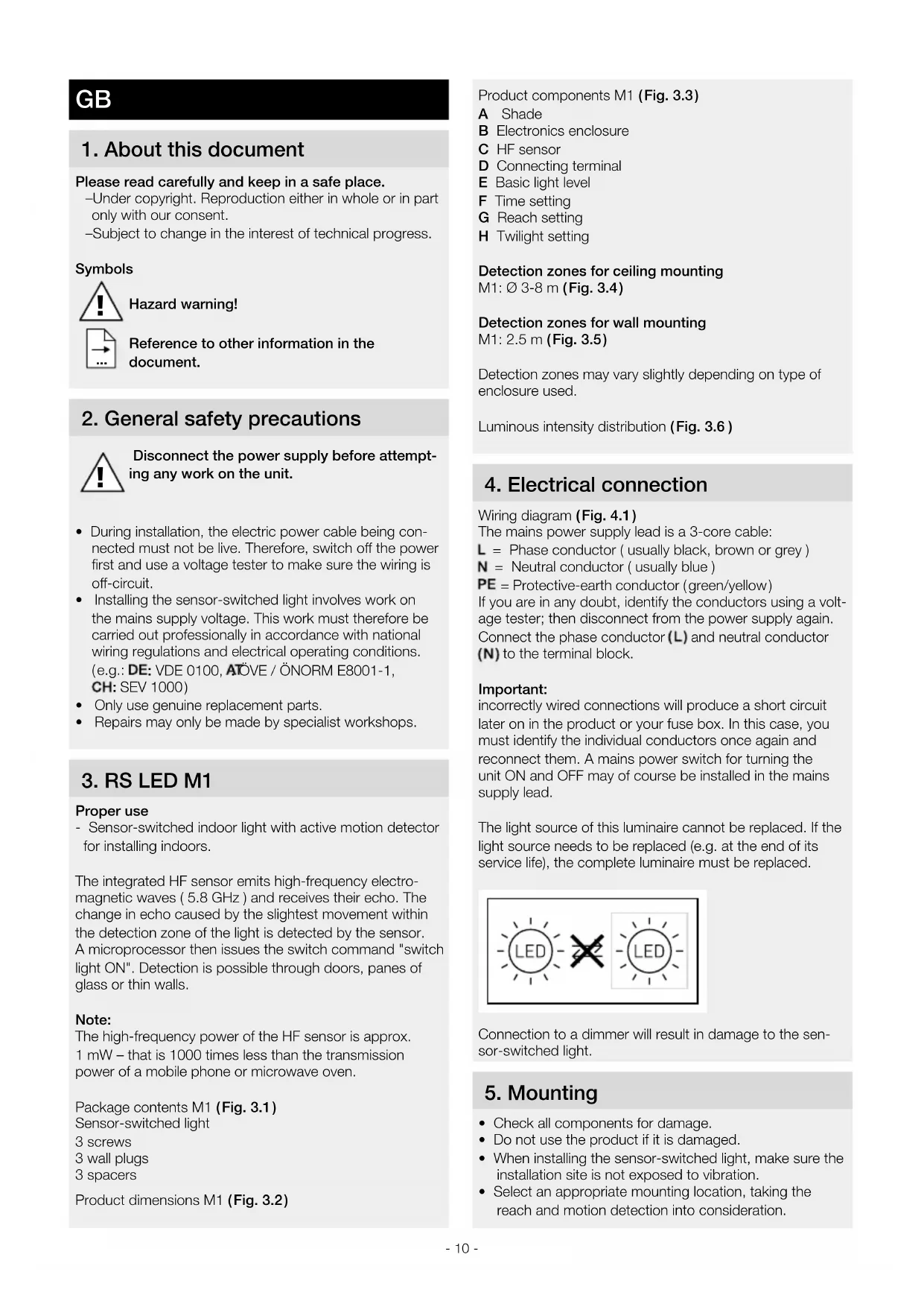
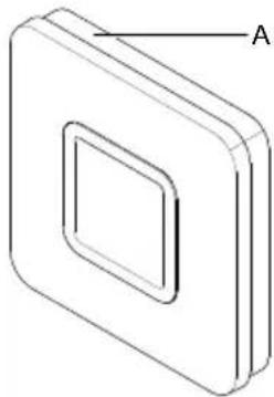
Product components M1 (Fig. 3.3)
A Shade
B Electronics enclosure
C HF sensor
D Connecting terminal
E Basic light level
F Time setting
G Reach setting
H Twilight setting
Detection zones for ceiling mounting
M1: ∅ 3-8 m (Fig. 3.4)
Detection zones for wall mounting
M1: 2.5 m (Fig. 3.5)
Detection zones may vary slightly depending on type of enclosure used.
Luminous intensity distribution (Fig. 3.6)
4. Electrical connection
Wiring diagram (Fig. 4.1)
The mains power supply lead is a 3-core cable:
L = Phase conductor ( usually black, brown or grey )
N = Neutral conductor ( usually blue )
PE = Protective-earth conductor (green/yellow)
If you are in any doubt, identify the conductors using a voltage tester; then disconnect from the power supply again.
Connect the phase conductor (L) and neutral conductor (N) to the terminal block.
Important:
incorrectly wired connections will produce a short circuit later on in the product or your fuse box. In this case, you must identify the individual conductors once again and reconnect them. A mains power switch for turning the unit ON and OFF may of course be installed in the mains supply lead.
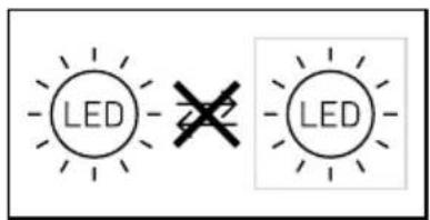
The light source of this luminaire cannot be replaced. If the light source needs to be replaced (e.g. at the end of its service life), the complete luminaire must be replaced.
text_image
LED LEDConnection to a dimmer will result in damage to the sensor-switched light.
5. Mounting
- Check all components for damage.
- Do not use the product if it is damaged.
- When installing the sensor-switched light, make sure the installation site is not exposed to vibration.
- Select an appropriate mounting location, taking the reach and motion detection into consideration.
Mounting procedure
- Switch OFF power supply (Fig. 4.1)
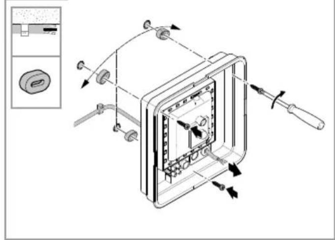
• Mark drill holes (Fig. 5.1) - Drill holes and insert wall plugs (Fig. 5.2)
• Installation with concealed power supply lead (Fig. 5.3) - Installation with surface-mounted power supply lead (Fig. 5.4)
- Connect conductors (Fig. 5.5)
- Switch ON power supply (Fig. 5.7)
- Make settings (Fig. 5.6)
- Settings → "6. Function"
- Fit shade (Fig. 5.7)
6. Function
Factory settings:
Time setting: 5 seconds
Reach setting: M1: max. 8 m
Twilight level: 2000 lux
Basic light level: OFF
The sensor-switched light can be put into service after mounting the enclosure and connecting to the mains power supply. When putting into operation manually at the mains switch, the light will switch OFF after 10 seconds for the calibration phase and is then activated for sensor mode. It is not necessary to operate the mains switch a second time.
Function - control dials (Fig. 6.1)
Time setting (stay-ON time) (Fig. 6.1/F)
The light's ON time can be set to any period from approx. 5 seconds to a maximum of 15 minutes. Any movement detected before this time elapses will restart the timer.
Note:
After the light switches OFF, it takes approx. 1 second before it is able to start detecting movement again. The light will only switch ON in response to movement once this period has elapsed.
The shortest time setting is recommended when adjusting the detection zone and performing the functional test.
Reach setting (sensitivity) (Fig. 6.1/G)
Reach is the term used to describe the diameter of the more or less circular detection zone produced on the ground for a mounting height of 2.5 m.
-Control dial set to maximum = max. reach (M1: 8 m)
-Control dial set to minimum = min. reach (M1: 2,50 m)
Twilight setting ( response threshold ) ( Fig. 6.1/F)
The light's chosen response threshold can be infinitely varied from approximately 2 to 2000 lux.
-Control dial set to daylight mode (depending on ambient brightness)
-Control dial set to = twilight mode (approx. 2 lux)
The control dial must be turned to ⚙when adjusting the detection zone and performing the functional test in daylight.
Basic light level function (Fig. 6.1/E)
The basic light level function provides illumination at approx. 10% light output when the brightness setting is reached.
Movement in the detection zone switches the light ON at 100% brightness for the time selected.
Light switches OFF completely after the selected time has elapsed. If the brightness setting has not yet been reached, basic light is switched back ON again.
-Control dial set to = basic light level ON
-Control dial set to 0 = basic light level OFF
Basic light is ON when the level of light falls below the brightness threshold. Basic light is always ON when daylight mode is activated.
Basic light switches OFF every hour to measure ambient brightness. Basic light switches back ON again after a short period.
Manual override function
If an optional mains switch is installed in the mains supply lead, the following functions are available in addition to simply switching light ON and OFF:
Manual override (Fig. 6.2)
1) Activate manual override:
Switch OFF and ON twice. The light is set to manual override for 4 hours. Then it returns automatically to sensor mode.
2) Deactivate manual override:
Switch OFF and ON once. Light goes out or switches to sensor operation.
Important:
Switching must take place within 0.2 to 1 second.
7. Disposal
Electrical and electronic equipment, accessories and packaging must be recycled in an environmentally compatible manner.

Do not dispose of electrical and electronic equipment as domestic waste.
EU countries only
Under the current European Directive on Waste Electrical and Electronic Equipment and its implementation in national law, electrical and electronic equipment no longer suitable for use must be collected separately and recycled in an environmentally compatible manner.
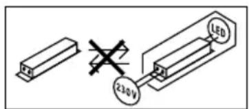
Important note: the control gear cannot be replaced.
text_image
230V LED8. Declaration of Conformity
STEINEL Vertrieb GmbH hereby declares that the RS LED M1 radio equipment type conforms to Directive 2014/53/EU. The full wording of the EU Declaration of Conformity is available for downloading from the following Internet address: www.steinel.de
9. Manufacturer's warranty
This Steinel product has been manufactured with utmost care, tested for proper operation and safety and then subjected to random sample inspection. Steinel guarantees that it is in perfect condition and proper working order. The warranty period is 36 months and starts on the date of sale to the consumer. We will remedy defects caused by material flaws or manufacturing faults. The warranty will be met by repair or replacement of defective parts at our own discretion. The warranty shall not cover damage to wear parts, damage or defects caused by improper treatment or maintenance. Further consequential damage to other objects shall be excluded.
Claims under the warranty will only be accepted if the unit is sent fully assembled and well-packed with a brief description of the fault, a receipt or invoice (date of purchase and dealer's stamp) to the appropriate Service Centre.
Repair service:
If defects occur outside the warranty period or are not covered by warranty, ask your nearest service station for the possibility of repair.

10. Technical specifications
Dimensions (H × W × D) M1: 200 × 200 × 53 mm
Supply voltage 220 - 240 V, 50 / 60 Hz
Power consumption ( P_on ) 8.80 W
Luminous flux * M1: 759 lm
Efficiency M1: 86 lm/W
Standby sensor ( P_sb ) 0.39 W
Mains current 46.50 mA AC
Power factor 0.93
Colour temperature 3,000 K (warm white)
Colour rendering index R
$$ _ \mathrm{a} = 8 3 $$
Average rated life expectancy L70B50 at 25°C: >60,000 hours
Colour consistency SDCM Starting value: 3
Luminous intensity distribution
| HF technology | 5.8 GHz (responds to the slightest movement regardless of temperature) |
| Angle of coverage | 360° with 160° angle of aperture |
| Transmitter power | approx. 1 mW |
| Detection reach | ∅ 3-8 m |
| Time setting | 5 s - 15 min |
| Twilight setting | 2 - 2,000 lux |
| Basic light level 10 % | |
| IP rating | IP20 |
| Protection class | II |
| Ambient temperature | -10°C to +40°C |
| Energy efficiency class | This product contains an energy efficiency class "F" light source. |
11. Troubleshooting
Malfunction Cause Remedy
| Sensor-switched light without power | ■ Fuse has tripped, not switched ON, break in wiring■ Short circuit in mains power supply lead■ Any mains switch OFF | ■ Activate, change fuse, turn ON mains switch, check wiring with voltage tester■ Check connections■ Switch on mains switch |
| Sensor-switched light will not switch ON | ■ Incorrect twilight setting selected■ Mains switch OFF■ Fuse has tripped | ■ Readjust■ Switch ON■ Activate, change fuse, check connection if necessary |
| Sensor-switched light will not switch OFF | ■ Continued movement within the detection zone | ■ Check detection zone |
| Sensor-switched light switches ON without any identifiable movement | ■ Light not mounted for detecting movement reliably■ Movement occurred, but not identified by the sensor ( movement behind wall, movement of a small object in immediate lamp vicinity etc.) | ■ Securely mount enclosure■ Check detection zone |
| Sensor-switched light does not switch ON despite movement | ■ Rapid movements are suppressed to minimise malfunctioning or detection zone set too small■ Incorrect twilight setting selected | ■ Check detection zone■ Readjust |
FR
M1: ∅ 3-8 m (afb. 3.4)
text_image
230 V LEDDimensioni (A x L x P) M1: 200 × 200 × 53 mm
text_image
230 V LEDPermanent lys (ill. 6.2)
1) Tenne permanent lys:
text_image
230 V LEDM1: ∅ 3–8 m (obr. 3.4)