MagicWatch WPS910 - Air-conditioner WAECO - Free user manual and instructions
Find the device manual for free MagicWatch WPS910 WAECO in PDF.
Frequently Asked Questions - MagicWatch WPS910 WAECO
User questions about MagicWatch WPS910 WAECO
0 question about this device. Answer the ones you know or ask your own.
Ask a new question about this device
Download the instructions for your Air-conditioner in PDF format for free! Find your manual MagicWatch WPS910 - WAECO and take your electronic device back in hand. On this page are published all the documents necessary for the use of your device. MagicWatch WPS910 by WAECO.
USER MANUAL MagicWatch WPS910 WAECO
m = 311

4
6x
4
city 1x10 km/h
1
2018年
16
4
16
5
2x
1
5x
3x
2
15
city 1x10 km/h
5
4x
2
16
5
5x
0
17
RESET
5x
6x
5s
5
7x
10s
16 17
5
8x
3
14
5
9x
8

6
1x
12
16 17

6
2x
25
CANH
city 1x10 km/h
62
∠X
乙
16 17
6)
3x
1 + u7 = 70%
6)
5x


6

7

| DE | EN | FR | ES | IT | NL | DA | SV | |
| bl | Blau | Blue | Bleu | Azul | Blu | Blauw | Blà | Blà |
| br | Braun | Brown | Marron | Marrón | Marrone | Bruin | Brun | Brun |
| sw | Schwarz | Black | Noir | Negro | Nero | Zwart | Sort | Svart |
| NO | FI | PT | RU | PL | CS | SK | HU | |
| bl | Blà | Sininen | Azul | Cánnei | Niebleski | Modră | Modră | Kěk |
| br | Brun | Ruskae | Castanho | Kopounchevskii | Bragów | Hnédá | Hnédá | Barna |
| sw | Svart | Musta | Preto | Heptu | Czamy | Čerma | Čerma | Fekete |

10
11

12
13


| DE | EN | FR | ES | IT | NL | DA | SV | |
| bl | Blau | Blue | Bleu | Azul | Blu | Blauw | Blà | Blà |
| br | Braun | Brown | Marron | Marrón | Marrone | Bruin | Brun | Brun |
| ge | Gelb | Yellow | Jaune | Amarillo | Giallo | Geel | Gul | Gul |
| gn | Grün | Green | Vert | Verde | Verde | Groen | Gron | Gron |
| or | Orange | Orange | Orange | Naranja | Arancio | Oranje | Orange | Orange |
| rt | Rot | Red | Rouge | Rojo | Rosso | Rood | Rad | Röd |
| sw | Schwarz | Black | Noir | Negro | Nero | Zwart | Sort | Svart |
| NO | FI | PT | RU | PL | CS | SK | HU | |
| bl Bla | Sininen | Azul | Csinh | Niebieski | Modră | Modră | Kék | |
| br Brun | Ruskea | Castanho | Kopruchneboy | Brzozowy | Hneda | Hnedá | Barna | |
| ge | Gul Keltainen | Amarelo | Jeßentny | Zólfy | Zluta | Zlá | Sarga | |
| gn | Grønn | Vihrea | Verde | Zelenny | Zelená | Zelená | Zöld | |
| or Orangesje | Oranssi | Cor de laranja | Opanjekby | Pomarañ-czowy | Oranzová | Oranzová | Narancs | |
| rt | Red | Punainen | Vermelto | Kpachny | Czernów | Cervena | Cervena | Piros |
| sw | Svart | Musta | Prato | Chepny | Czarny | Cerma | Cierna | Fekale |


www.dometic-waeco.com

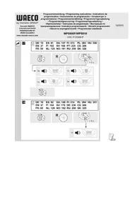
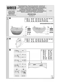
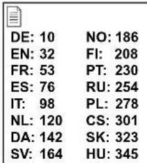
MagicWatch WPS900F/910
| DE 3 | Funk-Einparkhilfe Montage- und Bedienungsanleitung |
| EN 25 | Radio-based parking aid Installation and Operating Manual |
| FR 47 | Aide au stationnement radio Instructions de montage et de service |
| ES 69 | Sistema RF deutory para aparcar Instrucciones de montaje y de uso |
| IT 91 | Ausilio per il parcheggio Istruzioni di montaggio e d'uso |
| NL 113 | Draadloze parkeerhulp Montagehandleiding en gebruiks- aanwijzing |
| DA 135 | Trådløs parkeringshjælp Monterings- og betjeningsvejledning |
| SV 157 | Fjärr-parkeringshjälp Monterings- och bruksanvisning |
| NO 179 | Trådløs parkeringsassistant Monterings- og bruksanvisning |
| FI 201 | Langaton parkkitutka Asennus- ja käytöohje |
| PT 223 | Sistema de auxilio ao estacionamento por rádio Instruções de montagem e manual de instruções |
| RU 247 | Радиоуразьемы парковочьий радар Инструкция по мontаку и заимлуатуни |
| PL 271 | Radiowy system parkowania Instrukcja montažu i obstugi |
| CS 294 | Bezdrátový parkovaci asistent Námod k montáži a obsluze |
| SK 316 | Rádiový parkovaci asistent Námod na montáž a uvedenie do prevádzky |
| HU 338 | Rádiós parkolósegéd Szerelési és használati utmutató |
DE Fordern Sie weitere Informationen zur umfangreichen Produktpalette aus dem Hause Dometic WAECO an. Bestellen Sie einfach unsere Kataloge kostenlos und unverbindlich unter der Internetadresse: www.dometic-waeco.de
EN We will be happy to provide you with further information about Domatic WAECO products. Please order our free catalogue with no obligation to buy on our homepage: www.domatic-waeco.com
FR Demandez d'autres informations relatives à la large gamme de produits de la maison Domatic WAECO. Commandez tout simplement notre catalogue gratuite et sans engagement à l'adresse internet suivante : www.domatic-waeco.com
ES Solicitás more información sobre la amplia gama de produits de la Empresa Dometic WAECO. Solicite simplement nuestros catálogos de forma gratuite y sin compromiso en la direccion de Internet: www.dometic-waeco.com
IT Per ottenere maggiori informazioni sull'ampia gamma di prodotti Domatic WAECO è possibile ordinare una copia gratuite e non vincolante del nostro Catalogo all'indirizzo Internet: www.domatic-waeco.com
Maak kennis met het omvangrijke productscala van de firma Domatic WAECO. Bestel onsce catalogus gratis en vrijblijvend onder het internetadres: www.domatic-waeco.com
DA Bestil yderligere information om det omfattende produktudvalg fra Domatic WAECO. Bestil vores katalog gratis og uforpligtende på internetadressen: www.domatic-waeco.com
SV Inhämta mer information om den omfattande produktpalletten fran Domatic WAECO: Beställ våra kataloger gratis ochutan forpliktelser under var Internetadress: www.domatic-waeco.com
NO Be om mer informasjon om det rikholdige produktutvalget fra Domatic WAECO. Bestill var katalog gratis uforbindtlig på Internettadressen: www.domatic-waeco.com
Pyytää lisää tietoja Domatic WAECOn kattavista tuotevalikoimista. Tilatkaa tuotekuvastomme maksutta ja sitoumuksetta internet-osoitteesta: www.domatic-waeco.com
PT Peça mais informação sobre a ampla gama de produits da Empresa Domatic WAECO. Peça simplesmente os outros CATALOGOS de forma gratuita e sem qualquer compromisso, disponível no site: www.domatic-waeco.com
RU 3anpocnte daIbHeiuyo IHΦopMaunio o6 obuHnPOM accOpTmMeHTe npOdyKunn KOMnHN Dometic WAECO. IpoCTo 3akaxnte Haun KaTaNrHa caTe www.dometic-waeco.com; 3ta ycnyra npedocTabnEeTc8ecnnatno HN K Yemy He 063bIbaet.
PL Prosze sie zapoznać z informacjami na temat szerokiej gamy produktów Domatic WAECO. Prosze zamówic naz bezplaty katalog i zapoznać sie z niewiażȩcą oferta pod adresem: www.domatic-waeco.com
CS Žádejte další informace o rozsáhlé nabídce vyrobkú firmy Domatic WAECO. Stačí zdarma a nezávizně objednat naše katalogy na internetové adrese: www.domatic-waeco.com
SK Vyziadajte si dalsie informacia o rozsiahlej palette vyrobkov Domatic WAECO. Objnajte si bezplatne a nezavazne nas katalog na internetovej adre: www.domatic-waeco.com
HU Kérjen további információkat a Domatic WAECO cég széles körü termékpalettájáról. Rendelje meg ingyenes katalógusainkat kõtelezettség nélkül a következő internetcimen: www.domatic-waeco.de
Please read this instruction manual carefully before installation and first use, and store it in a safe place. If you pass on the product to another person, hand over this instruction manual along with it.
Table of contents
1 Safety and installation instructions. 26
2 Scope of delivery 27
3 Intended use 29
4 Pre-installation instructions 30
5Fitting the parking aid. 32
6 Connecting the parking aid 33
7 Detection range 35
8 Setting the system 36
9 Testing functions 41
10 Using the parking aid 41
11 Troubleshooting 43
12 Guarantee 45
13 Disposal 45
14 Technical data 46
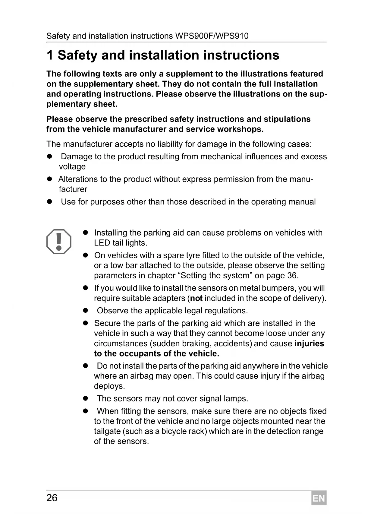
1 Safety and installation instructions
The following texts are only a supplement to the illustrations featured on the supplementary sheet. They do not contain the full installation and operating instructions. Please observe the illustrations on the supplementary sheet.
Please observe the prescribed safety instructions and stipulations from the vehicle manufacturer and service workshops.
The manufacturer accepts no liability for damage in the following cases:
- Damage to the product resulting from mechanical influences and excess voltage
- Alterations to the product without express permission from the manufacturer
- Use for purposes other than those described in the operating manual

- Installing the parking aid can cause problems on vehicles with LED tail lights.
- On vehicles with a spare tyre fitted to the outside of the vehicle, or a tow bar attached to the outside, please observe the setting parameters in chapter "Setting the system" on page 36.
- If you would like to install the sensors on metal bumpers, you will require suitable adapters (not included in the scope of delivery).
- Observe the applicable legal regulations.
- Secure the parts of the parking aid which are installed in the vehicle in such a way that they cannot become loose under any circumstances (sudden braking, accidents) and cause injuries to the occupants of the vehicle.
- Do not install the parts of the parking aid anywhere in the vehicle where an airbag may open. This could cause injury if the airbag deploys.
The sensors may not cover signal lamps. -
When fitting the sensors, make sure there are no objects fixed to the front of the vehicle and no large objects mounted near the tailgate (such as a bicycle rack) which are in the detection range of the sensors.
-
The parking aid is intended as an additional aid, which means it does not relieve you of the obligation to take due care when manoeuvring.
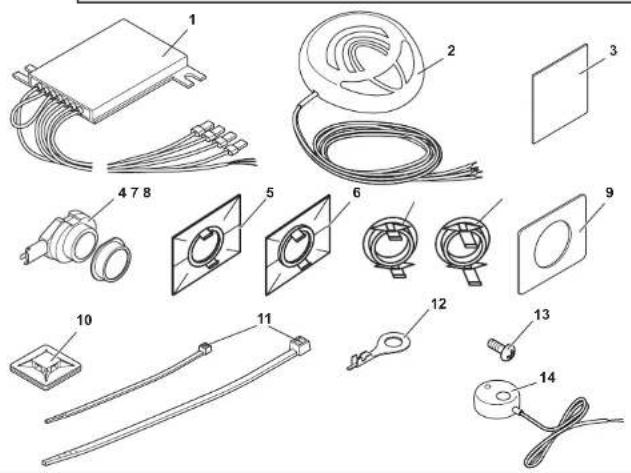
2 Scope of delivery
2.1 WPS 900F
| No. in fig. | Quantity Description Item no. | |
| 1 | 1 Control electronics 9101500031 | |
| 2 | 1 Control unit 9101500032 | |
| 3 | 2 Double-sided adhesive tape for control electronics and control unit | |
| 4 | 4 Ultrasonic sensors (brown) 9101500058 | |
| 5 | 4 Standard 0° sensor holder (fitted from the inside) | |
| 6 | 4 Standard 12° sensor holder (fitted from the inside) | |
| 7 | 4 0° sensor holder with cover ring (fitted from the outside) | 9101500004 |
| 8 | 4 12° sensor holder with cover ring (fitted from the outside) | |
| 9 | 5 Double-sided adhesive tape for sensors | |
| 10 | 4 Fastening holder | |
| 11 | 10 Cable binder, small | |
| 1 Cable binder, large | ||
| 12 | 1 Cable lug | |
| 13 | 1 Screw | |
| 14 | 1 External button 9103555920 | |
2.2 WPS 910
| No. in fig. | Quantity Description Item no. | |
| 1 2 Control electronics 9101500031 | ||
| 2 1 Control unit 9101500032 | ||
| 3 3 Double-sided adhesive tape for control elec- tronics and control unit | ||
| 4 | 2 | Ultrasonic sensors (blue) |
| 2 | Ultrasonic sensors (black) | |
| 4 | Ultrasonic sensors (brown) | |
| 5 8 Standard 0° sensor holder (fitted from the inside) | ||
| 6 8 Standard 12° sensor holder (fitted from the inside) | ||
| 7 8 0° sensor holder with cover ring (fitted from the outside) | 9101500004 | |
| 8 8 12° sensor holder with cover ring (fitted from the outside) | ||
| 9 9 Double-sided adhesive tape for sensors | ||
| 10 8 Fastening holder | ||
| 11 20 | Cable binder, small | |
| 2 | Cable binder, large | |
| 12 1 Cable lug | ||
| 13 1 Screw | ||
| 14 1 External button 9103555920 | ||
2.3 Accessories for WPS 900F/WPS 910
Available as accessories (not included in the scope of delivery):
Description Item no.
Sensor holder with silicon ring for metal bumper 9101500015 (VPE 4)
20^ sensor holder with cover ring (fitted from outside) 9101500023 (VPE 1)
Sensor extension cable 1.5 m 9103555747
Punching tool 22 mm 9101500024
Punching tool 18 mm 9101500013
3 Intended use
MagicWatch WPS900F (item no. 9101500019) and WPS910 (item no. 9101500020) are ultrasonic radio-based parking aids. When manoeuvring, they monitor the space in front of or behind the vehicle and emit an audible warning signal if they detect an obstacle.
MagicWatch is designed for installation in passenger vehicles with a width of up to 2.20 m.
4 Pre-installation instructions
4.1 Connection options
MagicWatch WPS900F and MagicWatch WPS910 can process either digital speed signals from the CAN bus (CAN bus connection on the loudspeaker) or an analogue speed signal (analogue connection on the front control electronics) to activate the front parking aid. A CAN bus connection is not possible in all vehicles with a CAN bus.

NOTE for vehicles with CAN bus
- The vehicle-specific product overview on the WAECO home-page will tell you whether a CAN bus connection is possible your vehicle.
"http://www.dometic-waeco.de/wps900", or call us and ask (for the contact information, please see the back of the instructions).
- If your vehicle features a CAN bus, but the vehicle list states that a CAN bus connection is not possible, MagicWatch WPS900F or WPS910 must be connected using a analogue connector. This will require analogue transmission of the speed signal.
If the vehicle does not provide a speed signal which is compatible (neither by CAN bus nor analogue), the front parking aid must be activated and deactivated using the timer function or the switch (see chapter "Setting the system" on page 36).
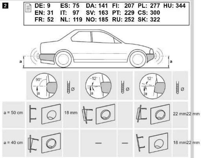
4.2 Determining the sensor installation position
See fig. 2 to fig. 5

NOTE
The sensors must be correctly aligned for the device to work properly.
If they point to the ground, irregularities and bumps on the surface may be interpreted as obstacles. If they point too far up, obstacles will not be detected at all.
Note the following during installation:
- The distance from the sensors to the ground should be at least 40~cm and a maximum of 50~cm (fig. 2).
- For the sensors to function optimally, the angle of the sensor to the road surface should be 90^ (fig. 2). The angle may not be less than 90^ , as the road will otherwise be interpreted by the sensor as an obstacle.
- The sensor holders included are suitable for all standard bumpers. Should the vehicle bumper be mounted at a steep angle, 20^ sensor holders with a cover ring are available as an optional extra (see chapter "Accessories for WPS 900F/WPS 910" on page 29).
- The sensor holders included are not suitable for installation in metal bumpers. If your vehicle has metal bumpers, you will need special sensor holders with a silicon ring (see chapter "Accessories for WPS 900F/WPS 910" on page 29).
- Note that the sensor holder depends on the installation height and the angle of the bumper. Select the right sensor holder and the appropriate drill diameter by consulting the table in fig. 2. The instruction manual shows how to install the standard sensor holder (fitted from the inside of the bumper), which produces the best visual result. Alternatively, the sensors can also be fitted using the sensor holders with cover ring which are provided.
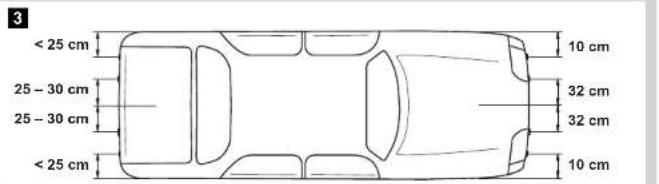
- Install the sensors in the correct position (fig. 5):
Colour of sensor Installation location
Blue (bl) Outer sides of the rear bumper
Black (sw) Middle sensors on the rear bumper
brown (br) Front bumper
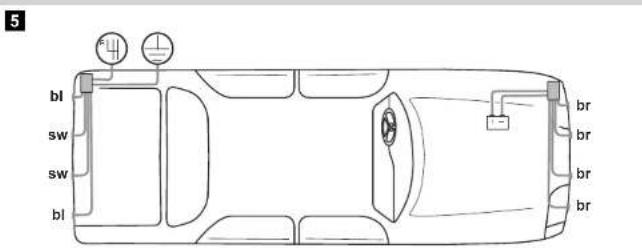
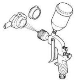
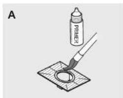
4.3 Painting the sensors
See fig. 6

NOTE
The sensors may be painted. The manufacturer recommends having the sensors painted by a specialist workshop.
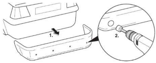
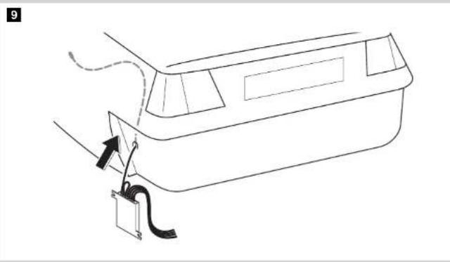
5 Fitting the parking aid

NOTICE!
On vehicles which feature metal reinforcement behind the bumpers, the sensors must not be touching this reinforcement. Otherwise there is no guarantee the parking aid will function correctly.
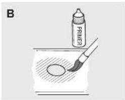
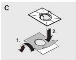
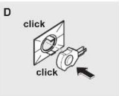
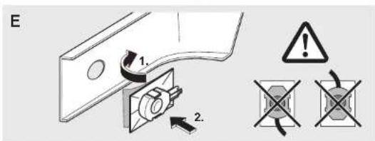
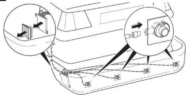
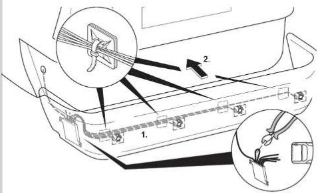
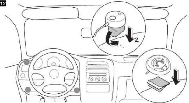
See fig. 7 to fig. 12
Supplements fig. 8

NOTICE! Risk of malfunction!
Align and attach the sensor holders correctly. Otherwise there is no guarantee the parking aid will function correctly.
The sensor holders must be attached with the retaining tabs pointing up and down.
Clean the adhesive surface on the inner side of the bumper with a primer.
Apply a small amount of grease inside the sensor plug connections.
Supplements fig. 11
Both the control electronics have been configured for front sensors by default. Define the control electronics for the rear sensors as follows:
Disconnect the cable bridges.
6 Connecting the parking aid

NOTE
- On some vehicles, the reversing light only works when the ignition is switched on. In this case, you must switch on the ignition in order to identify the positive and earth wires.
- You can set a switch-off time for the front system if you are unable to provide a speedometer signal for the front sensor control electronics (neither a digital connection via the CAN bus nor an analogue connection from the speedometer) (see chapter "Programming the system" on page 37 and fig. 19, parameter 1).
- You can connect the control electronics for the rear sensors directly to the continuous operating voltage or to the positive cable for the ignition (fig. 14) if you are unable to provide a reversing signal for the rear sensor control electronics (e.g. +12V contact voltage from the reversing light). This is only an option if you use the CAN bus connection to the control unit, and the vehicle CAN bus provides the reversing signal (see vehicle-specific product overview on the WAECO homepage "http://www.dometic-waeco.de/wps900").
- A reversing signal is not provided via CAN bus on all vehicles which allow a CAN bus connection.
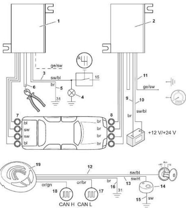
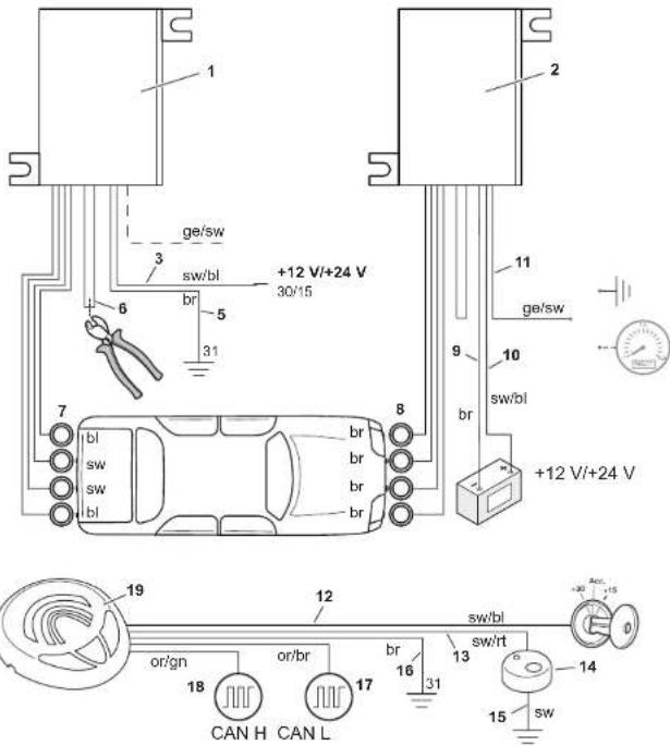
The complete circuit diagram can be found in:
- fig. 13 for reversing signal via reverse gear
- fig. 14 for reversing signal via CAN bus
No. Description
1 Control electronics for rear sensors
2 Control electronics for front sensors
3 Black/blue cable: connection to the reversing light
4 Reversing light
5 Brown cable: Connection to earth
6 Black cable bridge (connected = front unit/disconnected = rear unit)
7 Rear sensors
8 Front sensors
9 Brown cable: connection to the negative battery terminal.
10 Black/blue cable: connection to the positive battery terminal.
Yellow/black wire (for the front system only): Connection to earth Optional: connection to the speed signal from the speedometer
12 Black/blue cable: connection to connected positive (+12 V)
13 Black/red wire for the control unit: connection to the black/red wire of the external button
14 External button
15 Black wire from the external button: connection to earth
16 Brown cable: connection to earth
17 Orange/brown wire: connection to CAN Low
18 Orange/green wire: connection to CAN High
19 Control unit
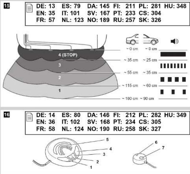
7 Detection range
See fig. 15
The detection range of the parking aid is divided into four zones (The figure applies accordingly for the front sensors):
Zone 1
This zone is the first limit range. Small objects or those with poor reflective characteristics may not be detected here.
Zone 2
Nearly all objects in this zone are displayed.
Zone 3
Nearly all objects in this zone are displayed, however objects may only appear in the sensors' blind spot, or not be detected at all due to their consistency or small size.
- Stop zone (4)
If there are objects in this zone, the parking aid emits a continuous tone warning you to stop.
Nearly all objects in this zone are displayed, however objects may only appear in the sensors' blind spot or not be detected at all due to their consistency or small size.
The distance at which the parking aid starts signalling you to stop can be set to different levels.
The display of fixed objects, such as a trailer hitch, can be suppressed.
8 Setting the system

NOTICE!
Incorrect settings can impair the operational safety.

NOTE
To stop setting the parameters without saving your changes, or to stop the entire set-up: refrain from pressing any buttons for a while.
8.1 Control elements
The control unit features the following control elements:
| No. in fig. 16Description |
| 1 Left button |
| 2 Red LED |
| 3 Yellow LED |
| 4 Right button |
| 5 Loudspeaker |
The external button features the following control elements:
| No. in fig. 16Description | ||||||
| 6 | LED | |||||
| 7 | B | u | t | t | o | n |
8.2 Learning the system

NOTE
You must carry out the learning procedure within 4 minutes of activating the front sensors. Once these 4 minutes have elapsed, the front system will stop sending an ID code.
The system communicates by radio contact. The control unit must be programmed to ensure it recognises the codes from the other devices.
See fig. 17
Start the programming procedure as follows:
Connect the voltage supply for the front control electronics.
Switch on the ignition.
Engage the reverse gear.
Press the left and right button on the control unit simultaneously for 5 seconds.
- The loudspeaker will emit two tones and the red and yellow LEDs will light up twice.
Let go of the two buttons.
Wait for a high-pitched tone and for the yellow LED to light up.
WPS910 only: Wait for a low-pitched tone and for the red LED to light up.
Wait for the loudspeaker to emit three tones and for the yellow and red LED to light up three times.
Switch the ignition off.
8.3 Programming the system

NOTE
Adapt the programming of the parameters to the type of installation you have carried out.
You can programme diverse settings.
See fig. 18
Start programming as follows:
- Switch on the ignition.
- Engage reverse gear.
- Press the left button on the control unit for 5 seconds.
The loudspeaker emits a peep tone once, and both LEDs light up.
Set the preferred value (fig. 19; chapter "Programming functions" on page 39).
The right button of the remote control is used to set the tens, and the left button is used to set the units for the preferred value. For example, if you wish to set the function "24", press the right button twice and the left button four times.
Once you have set the desired value, wait until the loudspeaker beeps in accordance with the value you have set and the respective LED flashes accordingly.
Switch the ignition off.
Configuring the front sensors
The front parking aid is always activated when you:
- Switch on the ignition
- Engage the reverse gear (WPS910 only)
- Briefly press the right button on the loudspeaker (< 5 seconds)
- Press the external button (< 5 seconds)
Programming functions
You can also set the function for the front sensors by programming it once, using the following method, among others (see fig. 19):

NOTE
The default settings are printed in bold in the table fig. 19.
- Parameter 1: Speed signal/time-out front sensors (function 13 - 16)
Default setting: speed-dependent
Function 13 (speed-dependent) is set by default. If there is no speed signal available which is compatible, you have the alternative of using the time-out to deactivate the front parking aid. Once activated, the programmed time period starts counting down.
If there is an obstacle in the detection range when the time period is over, the front parking aid remains active. Only when no obstacle is detected for more than 5 s will the front parking aid shut down.
Parameter 2: Duration of the front sensor signal
Default setting: 1 sec.
Parameter 3: Choose the speed signal source
Default setting: Control unit
Parameter 4: Detection range of the inner front sensors
Default setting: 80 cm
Parameter 5: Detection range of the inner rear sensors
Default setting: 160 cm
- Parameter 6: Detection range of the outer front sensors
Default setting: 55 cm
Parameter 7: Detection range of the outer rear sensors
Default setting: 55 cm
Parameter 8: Stop zone for front sensors
Default setting: Corner sensors = 25 cm, middle sensors = 35 cm
- Parameter 9: Stop zone for rear sensors
Default setting: 35 cm
- Parameter 10: Volume of warning tones for front sensors
Default setting: High
Parameter 11: Volume of warning tones for rear sensors
Default setting: High
- Parameter 12: Suppress display of fixed objects Default setting: Off
- Parameter 13: Shut-down delay for rear sensors
Default setting: Off
Parameter 14: Number of speed signal pulses Default setting: 3 - Parameter 15: CAN bus status Default setting: On
- Parameter 16: City function (function 66) or speed-dependent activation and deactivation (function 67)
Default setting: Speed-dependent activation and deactivation
Speed-dependent activation and deactivation (function 67)
The default setting automatically activates the front parking aid at speeds below 10km / h and automatically deactivates at speeds above 10km / h .
Connecting a compatible speed signal is essential for this function to work.
City function (function 66)
This function deactivates the front parking aid the first time a speed of 10km/h is exceeded and does not activate it again when the speed falls below 10km/h . It is only activated:
- the next time the reverse gear is engaged
- when the right button on the loudspeaker is pressed
- when the external button is pressed ( < 5~s~ )
The next time the ignition is started, the initial 10km / h limit is activated again.
Connecting a compatible speed signal is essential for this function.
This function is useful when, for example, the parking aid is considered a nuisance while driving in city traffic when roads are full, or in traffic jams.
Parameter 17: Reset to default settings
9 Testing functions
Complete the functional test of the rear sensors as follows:
Switch on the ignition and engage the reverse gear.
Be very careful when you use the device for the first time, and make sure that you familiarize yourself with the various sequences of beeps (see fig. 15).

NOTICE!
In zone 4, some obstacles may not be detected, because they are no longer within range of the sensors (construction-related characteristic).
Test the front sensors the same way. To do so, drive slowly, for example, towards a wall.
10 Using the parking aid
The rear sensors are automatically activated when you engage the reverse gear when the ignition is on or the engine is running.
The front sensors are activated automatically:
by starting the vehicle
by engaging the reverse gear
by lowering the vehicle speed to less than 10km / h
- by pressing the right button on the control unit
by pressing the external switch
When the front sensors are activated, the LED on the external button and the yellow LED on the control unit both light up.
If the speedometer signal cannot be detected, the front sensors are activated when the ignition is switched on. Once the adjustable switch-off time has elapsed, they are deactivated automatically.
As soon as there is an obstacle within the detection range, a steady signal tone is emitted repeatedly.
As you approach, the tone sequence will change according to the zone in which the obstacle is, thereby indicating the distance (fig. 15 applies to the front sensors).
Be very careful the first time you use the system, until you are familiar with the various sequences of beeps.
The front sensors are deactivated when
the speed of the vehicle is more than 10km / h
- you press the external button or the right button on the control unit briefly Press one of the two button for at least 5 s to deactivate the front sensors until the next time the vehicle is started.

NOTICE!
Stop the vehicle immediately and investigate the situation (getting out if necessary), if the following happens while you are manoeuvring:
the device first indicates an obstacle and the tone sequence speeds up normally (e.g. from slow to medium) when manoeuvring. The signal tone suddenly slows down, or no obstacle is indicated at all.
This means that the original obstacle is in the blind spot of the sensors (construction-related characteristic), and there is still a potential for collision.

NOTICE!
Be especially careful when manoeuvring after the system has been disconnected from the front or rear sensors.
The system will indicate this fault by:
the speaker will emit a double alarm tone.
- the red LED in the control unit and the LED on the external button flash continuously.

NOTE
When the stop zone is reached, the volume of the continuous tone will fall by about 50% after a short time.
11 Troubleshooting
The device shows no function.
The cables to the reversing light are not connected or are not properly connected.
The plugs for the sensors are not connected or are not correctly plugged into the control electronics.
Check the plugs and make sure they lock into place.
The speaker emits a double alarm tone, and the red LED in the control unit and the LED on the external button flash continuously
The system has been disconnected from the front or rear sensors. This can occur due to interference in the frequency range. Reprogramme the control modules (see chapter "Learning the system" on page 37).
Audible error signal is emitted for three seconds after engaging the reverse gear, following by a sequence of tones.
One or more sensors are defective or no longer connected to the control electronics. The LEDs in the control unit and the LED on the external button are flashing rapidly. The sequence of tones following the continuous tone indicate which sensor is defective:
- high tones for the front sensors
(e.g. two high tones for front sensor no. 2) - low tones for the rear sensors
(e.g. three deep tones for front sensor no. 3)
The sensor with the shortest cable is sensor no. 1, the one with the longest cable is sensor no. 4.
Check the plugs and make sure they lock into place.
Replace the defective sensor(s).

NOTICE!
The system does not work if one or more sensors are defective.
The front sensors shut down too early
The front sensors shut down before the speed reaches 10km / h . The LEDs in the control unit and on the external button switch off.
Set parameter 14 ("number of speed signal pulses") to function "59", "61", "62" or "63" (see chapter "Programming the system" on page 37).
Device indicates obstacles incorrectly
False alarms may have the following causes:
- Dirt or frost on the sensors
Clean the sensors.
Rain
Check whether the front sensors are deactivated at a speed exceeding 10km/h .
Check whether a compatible speed signal is available.
If there is no speed signal available, set parameter 1 ("Speed signal/Time-out front sensors") to function "14", "15" or "16" (see chapter "Programming the system" on page 37).
The sensors were incorrectly installed.
Adjust the position or height of the sensors (fig. 2).
Make sure that the appropriate sensor bracket was used (0^ / 12^ / 20^ / bracket for metal bumpers).
The sensors are in contact with the chassis.
Separate the sensors from the chassis.
No acoustic signal.
Check whether the yellow LED in the control unit and the LED on the external button light up.
When the LEDs are flashing, the system is in emergency mode. Start the vehicle again.
Objects on the vehicle (e.g. spare wheel) result in false alarms.
Set parameter 12 ("Suppress display of fixed objects") to function "52", "53" or "54" (see chapter "Programming the system" on page 37).
12 Guarantee
The statutory warranty period applies. If the product is defective, please contact the manufacturer's branch in your country (see the back of the instruction manual for the addresses) or your retailer.
For repair and guarantee processing, please send the following items:
Defect components
A copy of the receipt with purchasing date
- A reason for the claim or description of the fault
13 Disposal
Place the packaging material in the appropriate recycling waste bins wherever possible.
If you wish to finally dispose of the product, ask your local recycling centre or specialist dealer for details about how to do this in accordance with the applicable disposal regulations.
14 Technical data
| MagicWatch WPS900F | MagicWatch WPS910 | |
| Item no. 9101500019 9101500020 | ||
| Detection range Stop zone: Measuring range: | Approx. 0.1 m to 0.25 m Approx. 0.25 m to 0.9 m | Approx. 0.1 m to 0.3 m Approx. 0.3 m to 1.8 m |
| Ultrasound frequency: 40 kHz | ||
| Transmission frequency: 868 kHz | ||
| Supply voltage: 9-30 volts | ||
| Current consumption Operating: Standby: | Max. 180 mA 8.5 mA | Max. 240 mA 8.5 mA |
| Operating temperature: -25 °C to +70 °C | ||
| Certification: | e12 | |

NOTE
The sensors may be painted. The manufacturer recommends having the sensors painted by a specialist workshop.
8 Stalla in systemet

OBSERVERAI!
8 Stille inn systemet

PASS PAI
4.1 BapnaHTbI NOdkJIIOUcHnA
MagicWatch WPS900F and MagicWatch WPS910 pour actibuobnna nepe-dnerapkoohoro paapa moryt obpaabatb ninn cnpoBOn cnHan ckopoctn ot CAN-Bus (CAN-Bus-cBra3b c rpoMKOROBOpTeJeM), nnn aHaIoroBbIN CNrHANCKOPoCTN (aHaIoroBaJcBra3b c pepeDHeJ 3JIeKTPOHNKOynpaBLeHn). He drr BceX abTomo6nJe c CAN-Bus BO3MOxHa CAN-BusCBra3b.

YKA3AHNEДЯаьмомobuilecCAN-Bus
Bo3moKHa IIN CAN-Bus-cBra3b IJI BaUero aBTOMo6nIa, Bbl MoKeTe y3HaTb I3 nepeuHЯ nporpAMM IJIa ABTOMo6nIeJ, npIBeDeHHbIX Ha caIte KOMNaHn WAECO http://www.dometic-waeco.de/wps900,, HII CBra3aBwncb C Hamn No TeJeFOHy (KOHTaKTHbIe DaHHbIe npIBeDeHbI Ha o6OpOTHOJ CTOpOHe NHCTpyKcN).
- Ecnn Baaw abTomobnIb nMeet CAN-Bus, Ho cornacho cnNcky CAN-Bus-cBra3b He Bo3MoJxHa, To dJa MagicWatch WPS900F nn WPS910 Heo6xoJmo NcnoJb3ObaTb aHaJorOByIO CBA3b. DnA 3TOrO DoJXeH nMeTbcraCnHaJI CKOpOCTu B aHaJorOBOBOM BVne.
Ecnn aBTOMO6nIb He npedocTabnreT rDhBn IJN HCNoJIb3OBaHnra CnHaJI cKOpocTn (Hn CAN-Bus, Hn aHaIorOBbI), TO nepeHn napKOBOUHbI paIap Heo6xOIMo aKTINBnPOBaTb NII DeAKTNBnPOBaTb C NOMUbO fynKcHn TaI-Mepa nnnepeKnIOuataTelem (cm. rI. «HaCTpoNka cnCTeMbI» Ha cTp. 258).
4.2 OnpeJeHne MeCTa MOHTaxa DaTUnKOB
CM.pnc.2-pnc.5

YKA3AHNE
Baxhblm ycnoBnem 6ecnepeboHo paobtbp npnbopa rBnaeTc npaBnIbHa peylnpOBKa daTUnKOB.
EcnOn OHH ObaeHbIB 3emJIHO, To, HapnIpMep, HepOBHocTn DOpOrn pacNo3HaOTcK KaK npenrTCTBnR. EcnOn OHn NODHrTbI CInuKOM CNJbHO BBePx, To IMeUouneCnpeNrTCTBnR He paCnO3HaOTcR.
Pn moTaxe co6IouaIte cneDyUoIe yka3aHna:
PacctoHne OT daTnKOB Do 3eMn DOJXHO COCTaBnTb He MeHee 40 cm n He 6Onee 50 cm (pnc. 2).
- Дя ONТIMально pa6OTbI yroJ haKNoHa dAteHka KdoPoXHOMy noIoTHydoJxHcOCTaBnTb 90° (pnc. 2). YroJ He doJxHe COCTaBnTb MeHee 90°, T. K. B 3Tom cIyuae dopoxHoe nOToTHo pacno3HaeTcR daTychKOM KaK npenrTCTBne.
Bxodjune B objem noctabkn depkaTeJn daTchkoB npirohbl IJI HaIbOJee pacnpoctpaHeHHbIX 6amnepoB. Ecn 6ampepbI aBTOMobnJIy MeOT cInbHbI HaKIOH, TO B KaueCTBe OUcN INpeDnaRaETcR daPkaTeJIb DaTUnKa 20^ C npedoxpaHHTeHbIM KOJBcOM rI. «PpHaadJeXHOCTn DnA WPS 900F/WPS 910» Ha cTp. 251).
Bxodjune B objem noctabkn depxaTei DaTynKOB He npirohbl dJMy MoHTaxa B MeTaNueckne 6amnpbI. Ha 3OT cnyaH TpebyotcCneuNbHbIe depXaTei DaTynKOB C CNIKHOHBIM KOJbUOM (CM. rI. «PnHaadJeXHoCTn dJa WPS 900F/WPS 910» Ha cTp. 251).
- YuTHe, YTO DePkaTeIb DaTuNka 3aBnCt OT BbICOTbl MOHTaKa HnKNoHa 6ampepa. BbIbepnte cornacho Tabnue Ha pnc. 2 NOxOJa- uHn DepKaTeIb DaTuNKOB, a TaKke COOTBeTCTByUoUsn DNAmETp OTBepcTn. B nHCTpykun NOKa3ah MOHTaX CTaHdApTHbIX DePkaTeJe DaTuNKOB (MOHTaX C BHyTpEnHne CTOpOnbI 6ampepa), T. K. B 3ToM cIyuae DOCTnraETCa HnIyUwI pe3yJbTaT C TOUKN 3peHnBHeWHeRo BVda. B KaueCTBe aIbTePhaTNBbl MOxHO TaKxe yCTaHaBnBaTb DaTuNKn C NOMO- uBXODaXx Obem NoCTaBKn DePkaTeJe C npedoxpaHNTeNbHbIM KOJIbCuom.
- YctaHOBNTe DaTUnKn B NOxOJaIeM MeCTe (pnc. 5):
B 300 He OTo6paKaHOTc NaTn Bce oBeKtbl.
3oha 3
B 3Toi 30He OTo6paKaIOTcI NOuTn BCE ObBeKtbl, Ho HeKOToPbIe IpeIdMeTbI MOrY T Nonactb B «MePTbYHO 3OHy» DaTuNKOB NIN He paCNo3HaBaTbcra BCNeIDCTBne INX CBOIcTB INN He6OJIbWoB BeINuHbI.
3oHa ocTaHOBKn (4)
OsbapykeHne obBeKTOB B 3ToI 30He BeTeT K TOMy, YTO npkoBOHbI paadap HnpepbIBHbIM CNrHaIOM npeDynpexJaet O Heo6xOJMOCTN OCTaHOBKn.
B 301 301 0T6paKaOTcN OHTN Bce 0bEeKtbl, HO HeKOToPbIe npedMeTb MOrY T nonactb B «MePTByIO 3OHy» DaTUnKOB Nn He paCNo3HaBaTbCS BCJeDCTBNE INX CBOJCTB INN He6OJbWOn BeINuHbI.
PacctoHne,Haunha c KOTOPOrO napKOBOuHbI paadp npedynpeJdaeT O Heo6xOdIMOCtN OCTaHOBKn, MoXHo peryInpoBaTb CTyneHcato.
CnHajn3aunO cTaunOHapbIX obBeKToB, HApnPmep, TAreBO-CcENHOYCTPOICTBa, MOxHo NCKJIouHTb.
8 Hac tropona cnctembl

BHUMAHNE!
HenpaBnIbHbIe HacTpoKmOryT OtpuCaTeJbHo cKa3aTbcra Ha NaedxHocTn pa60Tbl.

YKA3AHNE
Для перьваня Habtroponи napametpoB, He coxpaHЯ nx, Или Для 3abepseHЯ Bcei proucedypbI Habtropon:ДпntelbHoeВрем He HaximaiTe HN ODNy N3 KHOJOK.
8.1 OprahbI ynpaBneHnA
KoHcHpyaunpeepnX daTynkoB
IpeHn npKOBOHyI paap Bcerda aKTINBnpyETcB TOM clycae, ecn Bbl
BKJIIOUaTe 3aXnraHne
BkIIOUaTe npepaCy 3aHero xoJa (ToJIbKO WPS910)
KOPOTKO HaximaeTe npaByIO KhoNky y rpoMkoROBOpuTeTnA (< 5c)
- HaxkmaeTe BHeUHn NepeKIOuAteIb (< 5 c)
PporpammpoBaHne yHKn
BbIMoKeTe HacTpoNTb pa6Otu nepeDnX daTUnKOB nyTeM OndHopa30BOrO nporpaMMnpOBaHnA cNeIyUoIm o6pa3OM (cM. pnc. 19):

YKA3AHNE
B tabnue pnc. 19 3aBOdCKne HacTpoiKn BblJeHbI XnnpHbIM wnpfTom.
- Napametp 1: CnHaJI CKOpOCTN/OTKnIOUeHne IpeEHNX DaTUnKOB NO BpeMeHn (Функця 13 - 16)
3aBoDcKa HaCTpoIka: B 3aBnCmOCTn OT CKOpOCTn
ПризавODбкои habсгрьке habсгрьафункця 13 (В завсимости OT ckорoctи).Есни He ImeetcprnroDHorO Дя ИСпОьЗOBаня сИнhaлacKOPoCTN,TOВКaчecTbe aIbTePHaTINbIперEDн NapkoBoUHbI paIapMOжET OTKJIIOuATbcrCpeRyJInpOBKONo BpeMeHN.ПриakTNBupOBahnIHauHHaETcOTCuET 3anporpaMMIpOBaHHORO npOMeЖуTkBaBpeMeHN.
Ecnn no nCTeHnn npomexyTKa BpeMeHN B dnaNa3OHe OXBata nMe-ETc npenTCTBne, To nepdHn napKOBOHybI paadap OCTaeTc aKTHbIM. TOnbKO B TOM clyuae, ecn 60nee 5 cekynd He pacno3Haetc KaKoe-Ni6o npenTCTBne, nepdHn napKOBOHybI paadap BbIKNoHuca-ETcra.
- Napametp 2: Д闪电ьноctь сигнaja nepeDHnx dATyNKOB
3aBODsKaHaCTpOJa:1c
- Napametp 3: Bb6op nCTouHnka cnHaJa cKOpocTn
3abOcka HacTpoKa: BloK ynpaBneHna
- BBICOKHe 3ByKOBbIe CnHaNbI DnI nepeDnIX DaTnKOB (HaIpIMep, IBa BbICOKHX 3ByKOBbIX CnHaNa O3HaauOT HeNCnPabBHOCTb nepeDHeRo DaTnKa No 2)
- HN3KHe 3ByKOBbie CnHaNbI DJIa3aDHnx DaTChKOB (HaNPIMep, TPN HN3KHX 3ByKOBbIX CnHaNa O3HaauOT HeNCnPpABHOCTb 3aHrero DaTUnKa No 3)
Датунк с самын КОРOTКИМ Кабелем -эTO датунк № 1,с самын ДЛINHHын -датунк № 4.
Проверъшт ekрьи,пгн Heo6xOДMOCTN,ВCTaBbTe INX NOBTOPHO TaK, yTO6bl OHN 3aФИКСИРОВАЛNCb.
3aMeHnTe HeNCnpaBhIe DaTUnKn.

BHUMAHNE!
CnCTema He pa6oTaet, ecn HncnpaBeH OINn IIN HeCKOJIbKO DaTUnKOB.
Ipeedne daTcIKN OTKIOUaOTcCNIuKOM paHO
Ipeednne daTunKoTKnOIOuOTc npexde, yem doCTnraeTcckopocb 10 KM/uy CBeToNDoBbl 6Ioka ynpabNeHnBHeUHero nepeKIOuataJIy BbIKIOuOHTcR.
HactpoIte npametp 14 (KolnueCTBO mnybcob cnHaJa cKOpocTn) Ha cyHKUIO 59》,61》,62》 nIIu 63》(cm. rI. PporpaMMnpOBaHne cnCTeMbI» Ha cTp. 260).
Pn6op HeBepHo cnHaHn3npyeT npenrTCTBna
Cneyuoune npuHbMOyT npBODntb K HeBepHOcHn3aun:
- Tp3b nIeI Ha daTcKax.
OuNTte DaTUnKn. - DOKb
Проверъ,OTКИюаIOTcЯлпелpeДнe ДaТчИКn CkОpoCTbIO DBNXeHnA CBblse 10 KM/ч.
Проверъ,ИмeeТялВ рацпоржЕнnpиroДьй ДЯ ИСпОьБ3OBa-HNЯ CnHaj CKOpOCTN.
Ecn He nmeetc cnHaIa ckopocTn, To hactpoite napameTp 1 («CnrHaNCKOPoCTN/OTKJIIOueHne nepeDnX daTunKOB no BpeMeHn») Ha cyHNKcUIO «14», «15» nII «16» (cm. rI. «IporpaMMIpObaHne cncTeMbI» ha ctp. 260).
-Датчickenбылн He npabnIbHo yctaHOBJIeHbl.
ИзMeHnte noIoxeHne nII BbICOTy daTUnKOB (pnc. 2).
Y6eIntecb B TOM, yTo6bl 6bln npImHeHbl nOxDxOJaUne DepeKaTeJI NaTUnKOB (0°/12°/20°/depeKaTeJI nIra MeTaJIInuecknx 6amNepOB).
-ДатчИКИ IMeHOT KOHTaKT C paMOй XODOBОй чАТи.
YcTpaHInTe KOHTaKT DaTcuNKOB C paMOI XoIOBOJ YaCTN.
OtcytCTByeT akyctueckn cnrhan
Проверът,сьетясглжелынсветоюдблoka упраьени и свettingоюдВHEшero nepeknючateя.
Ecni CBeToOnOdbI MnraHOT, 3TO O3HauaeT, YTO CNCTema HaxoJNTcB aBa-pinHom peXnme.
IOBTOpHO BkJIouHTe 3aXnraHHe.
ObbeKtbl Ha aBTOMo6nJe (HaPnPmep, 3aNaChoe KOneco) BeyT K HeBepHOcHn3aun
HactpoTe npametp 12 («ИckIIOueHne cnHaJIIN3aUIn CtaUIOHapHbIX o6beKToB») Ha φyHKUIO «52», «53» UIN «54» (cM. rII. «ПрогpaMMnpoBaHne CNCTeMbI» Ha cTp. 260).
12 RapaHTnA
Dometic Australia Pty. Ltd.
1 John Duncan Court
Varsity Lakes QLD 4227
+61755076000
+61755076001
Mail: sales@dometic-waeco.com.au
AUSTRIA
Dometic Austria GmbH
Domatic Italy S.r.l.
Via Virgilio, 3
I-47100 Forl
+390543754901
+390543756631
Mail: info@dometic.it
NORWAY
Dometic Norway AS
Skolmar 24
N-3232 Sandefjord
+4733428450
+4733428459
Mail: firmapost@waeco.no
POLAND
Domatic Poland Sp. z o.o.
UI.Pulawska 435A
02-801 Warszawa
Poland
+48224143200
+48224143201
Mail: info@dometic.pl
RUSSIA
Dometic RUS LLC
Komsomolskaya square 6-1
107140 Moscow
Russia
+74957807939
+74959165653
Mail: info@dometic.ru
SLOVAKIA
Domatic Slovakia s.r.o.
Tehelná 8
SK-98601 Filakovo
+421474319107
+421474319166
Mail: info@dometic.sk
SPAIN
Dometic Spain S.L.
Avda. Sierra del Guadarrama, 16
E-28691 Villanueva de la Canada
Madrid
+34902111042
+34900100245
Mail: info@dometic.es
SWEDEN
Dometic Scandinavia AB
Gustaf Melins gata 7
Domatic Switzerland AG
Riedackerstrasse 7a
CH-8153 Rümlang (Zürich)
+41 44 8187171
+41448187191
Mail: info@dometic-waeco.ch
TAIWAN
WAECO Impex Ltd.
Taipei Office
2 FL-3 · No. 56 Tunhua South Rd, Sec 2
Taipei 106, Taiwan
+886227014090
+886227060119
Mail: marketing@dometic-waeco.com.tw
UNITED KINGDOM
Domatic UK Ltd.
Dometic House · The Brewery
Blandford St. Mary
DorsetDT119LS
+448446260133
+448446260143
Mail: sales@dometic.co.uk
UNITED ARAB STATES
Domatic Middle East FZCO
P.O.Box 17860
S-D 6, Jebel Ali Freezone
Dubai, United Arab Emirates
+97148833858
+97148833868
Mail: info@dometic.ae
UNITED STATES OF AMERICA
Dometic Marine Division
2000 N. Andrews Ave. Extension
Pompano Beach, FL 33069 USA
+19549732477
+19549794414
Mail: marinesales@dometicusa.com