MagicWatch WPS900F - Air-conditioner WAECO - Free user manual and instructions
Find the device manual for free MagicWatch WPS900F WAECO in PDF.
Frequently Asked Questions - MagicWatch WPS900F WAECO
User questions about MagicWatch WPS900F WAECO
0 question about this device. Answer the ones you know or ask your own.
Ask a new question about this device
Download the instructions for your Air-conditioner in PDF format for free! Find your manual MagicWatch WPS900F - WAECO and take your electronic device back in hand. On this page are published all the documents necessary for the use of your device. MagicWatch WPS900F by WAECO.
USER MANUAL MagicWatch WPS900F WAECO
flowchart
graph TD
    A["Speaker Icon"] --> B["R"]
    B --> C["Hand pointing to a component with '4' symbol"]
    C --> D[">5 s"]
    D --> E["1x magnified view of waveform pattern"]


DE: 17 ES: 83 DA: 149 FI: 215 PL: 285 HU: 352
EN: 39 IT: 105 SV: 171 PT: 237 CS: 308
FR: 61 NL: 127 NO: 193 RU: 261 SK: 330
| 1x | 3x | ||||
| 1 |  | 1x | 4x | 20 s | |
| 1x | 5x | 40 s | |||
| 1x | 6x | 60 s | |||
| 2 |  | 1x | 7x | 1 s | |
| 1x | 8x | 3 s | |||
| 1x | 9x | cont. | |||
| 3 |  | 2x | 1x | ||
| 2x | 2x | ||||
| 4 |  | 2x | 3x | 50 cm | |
| 2x | 4x | 80 cm | |||
| 2x | 5x | 90 cm | |||
| 5 |  | 2x | 6x | 120 cm | |
| 2x | 7x | 160 cm | |||
| 2x | 8x | 180 cm | |||
| 6 |  | 2x | 9x | 50 cm | |
| 3x | 1x | 55 cm | |||
| 3x | 2x | 80 cm | |||
| 7 |  | 3x | 3x | 50 cm | |
| 3x | 4x | 55 cm | |||
| 3x | 5x | 90 cm | |||
| 8 |  STOP ↔ STOP ↔ | 3x | 6x | A = 25 cm, B = 25 cm | |
| 3x | 7x | A = 25 cm, B = 35 cm | |||
| 3x | 8x | A = 35 cm, B = 50 cm | |||
| 9 |  | 3x | 9x | 30 cm | |
| 4x | 1x | 35 cm | |||
| 4x | 2x | 45 cm | |||
| 4x | 3x | 70 cm | |||
| 10 |  | 4x | 4x | ||
| 4x | 5x | ||||
| 4x | 6x | ||||
| 11 |  | 4x | 7x | ||
| 4x | 8x | ||||
| 4x | 9x | ||||
| 12 |  | 5x | 1x | 0 | |
| 5x | 2x | 1 | |||
| 5x | 3x | 2 | |||
| 5x | 4x | 3 | |||
| 13 |  | 5x | 5x | 0 | |
| 5x | 6x | 5 s | |||
| 5x | 7x | 10 s | |||
| 14 |  | 5x | 8x | 3 | |
| 5x | 9x | 8 | |||
| 6x | 1x | 12 | |||
| 6x | 2x | 25 | |||
| 6x | 3x | 30 | |||
| 15 |  | 6x | 4x | ||
| 6x | 5x | ||||
| 16 | City 1x 10 km/h | 6x | 6x | ||
 | 6x | 7x | |||
| 17 | RESET | 9x 9x | |||

1

text_image
DE: 5 ES: 71 DA: 137 FI: 203 PL: 273 HU: 339 EN: 27 IT: 93 SV: 159 PT: 224 CS: 295 FR: 49 NL: 115 NO: 181 RU: 249 SK: 317
text_image
Exploded view diagram of a smart electrical connector with numbered parts for identification
2

text_image
DE: 9 ES: 75 DA: 141 FI: 207 PL: 277 HU: 344 EN: 31 IT: 97 SV: 163 PT: 229 CS: 300 FR: 52 NL: 119 NO: 185 RU: 252 SK: 322
text_image
a 90° Ø -12° Ø 12° Ø a = 50 cm 18 mm 22 mm2 a = 40 cm - - 18 mm23

text_image
< 25 cm 25 - 30 cm 25 - 30 cm < 25 cm 10 cm 32 cm 32 cm 10 cm4

text_image
DE: 9 ES: 75 DA: 141 FI: 207 PL: 277 HU: 344 EN: 31 IT: 97 SV: 163 PT: 229 CS: 300 FR: 52 NL: 119 NO: 185 RU: 252 SK: 322
natural_image
Technical line drawing of a mechanical part with an inset magnified view showing a crosshair symbol (no text or labels)5

text_image
bl sw sw bl br br br br
6

natural_image
Line drawing of a spray gun with nozzle and spray bottle (no text or symbols)
| DE: 10 | NO: 186 |
| EN: 32 | FI: 208 |
| FR: 53 | PT: 230 |
| ES: 76 | RU: 254 |
| IT: 98 | PL: 278 |
| NL: 120 | CS: 301 |
| DA: 142 | SK: 323 |
| SV: 164 | HU: 345 |

7

text_image
Technical diagram showing a car door handle assembly with labeled parts and a magnified detail view of the component being inserted.8

text_image
DE: 10 ES: 76 DA: 142 FI: 208 PL: 278 HU: 345 EN: 32 IT: 98 SV: 164 PT: 230 CS: 301 FR: 54 NL: 120 NO: 186 RU: 254 SK: 323
natural_image
Illustration of a primer pen applying paint to a circular sample on a base (no text or symbols)
natural_image
Illustration of a brush applying paint to a surface with a labeled bottle (no text or symbols present)
text_image
C 1. 2.
text_image
D click click
text_image
E 1. 2.9

natural_image
Line drawing of a vehicle's front compartment with cable and plug, no text or symbols present| DE | EN | FR | ES | IT | NL | DA | SV | |
| bl | Blau | Blue | Bleu | Azul | Blu | Blauw | Blá | Blá |
| br | Braun | Brown | Marron | Marrón | Marrone | Bruin | Brun | Brun |
| sw | Schwarz | Black | Noir | Negro | Nero | Zwart | Sort | Svart |
| NO | FI | PT | RU | PL | CS | SK | HU | |
| bl | Blá | Sininen | Azul | Синий | Niebleski | Modrá | Modrá | Kék |
| br | Brun | Ruskea | Castanho | Коричневый | Brązowy | Hněda | Hnedá | Bama |
| sw | Svart | Musta | Preto | Черный | Czarny | Černá | Člema | Fekete |

10

text_image
Diagram showing car interior components with zoomed-in insets highlighting mechanical parts and wiring connections11
DE: 10 ES: 76 DA: 142 FI: 208 PL: 278 HU: 345
EN: 32 IT: 98 SV: 164 PT: 231 CS: 301
FR: 54 NL: 120 NO: 186 RU: 254 SK: 323

text_image
Technical diagram showing a car interior with labeled parts and two zoomed-in insets for detail or repair.12

text_image
Diagram of car interior showing dashboard, steering wheel, and gear shift indicators with numbered annotations13
DE: 12 ES: 78 DA: 144 FI: 210 PL: 280 HU: 347
EN: 34 IT: 100 SV: 166 PT: 232 CS: 303
FR: 56 NL: 122 NO: 188 RU: 256 SK: 325

text_image
1 ge/sw 3 sw/bl 6 br 5 31 4 7 bl sw sw bl 8 br br br br 15 11 ge/sw 9 br +12 V/+24 V 10 sw/bl 19 12 or/gn 18 or/br 17 br 16 31 sw/bl sw/rt 13 14 15 sw CAN H CAN L
14
DE: 12 ES: 78 DA: 144 FI: 210 PL: 280 HU: 347
EN: 34 IT: 100 SV: 166 PT: 232 CS: 303
FR: 56 NL: 122 NO: 188 RU: 256 SK: 325

text_image
1 ge/sw 3 sw/bl +12 V/+24 V 30/15 6 br 5 31 7 bl sw sw bl 8 br br br br br 9 gr ge/sw 10 sw/bl +12 V/+24 V 11 gr sw br 12 br br br br br 13 sw/bl +20 15 14 or/gn 18 or/br 17 CAN H CAN L 31 15 sw| DE | EN | FR | ES | IT | NL | DA | SV | |
| bl | Blau | Blue | Bleu | Azul | Blu | Blauw | Blà | Blà |
| br | Braun | Brown | Marron | Marrón | Marrone | Bruin | Brun | Brun |
| ge | Gelb | Yellow | Jaune | Amarillo | Giallo | Geel | Gul | Gul |
| gn | Grün | Green | Vert | Verde | Verde | Groen | Grøn | Grön |
| or | Orange | Orange | Orange | Naranja | Arancio | Oranje | Orange | Orange |
| rt | Rot | Red | Rouge | Rojo | Rosso | Rood | Rød | Röd |
| sw | Schwarz | Black | Noir | Negro | Nero | Zwart | Sort | Svart |
| NO | FI | PT | RU | PL | CS | SK | HU | |
| bl Blá | Sininen | Azul | Синий | Niebieski | Modrá | Modrá | Kék | |
| br Brun | Ruskea | Castanho | Коричневый | Brązowy | Hnăda | Hnedá | Barna | |
| ge | Gul Keltainen | Amarelo | Желтый | Żółty | Żlutá | Żńá | Sárga | |
| gn | Grønn | Vihreå | Verde | Зеленый | Zielony | Zelená | Zelená | Żöld |
| or Oransje | Oranssi | Cor de laranja | Оранжевый | Pomarań-czowy | Oranżová | Oranżová | Narancs | |
| rt | Rød | Punainen | Vermelho | Красный | Czerwony | Červená | Červená | Piros |
| sw | Svart | Musta | Preto | Черный | Czarny | Černá | Čierna | Fekele |

15
DE: 13 ES: 79 DA: 145 FI: 211 PL: 281 HU: 348
EN: 35 IT: 101 SV: 167 PT: 233 CS: 304
FR: 57 NL: 123 NO: 189 RU: 257 SK: 326

text_image
4 (STOP) 1 2 3 ~ 0 cm ~ 0 cm ~ 35 cm ~ 25 cm ~ 55 cm ~ 35 cm ~ 115 cm ~ 60 cm ~ 160 cm ~ 90 cm16
DE: 14 ES: 80 DA: 146 FI: 212 PL: 282 HU: 349
EN: 36 IT: 102 SV: 168 PT: 234 CS: 305
FR: 58 NL: 124 NO: 190 RU: 258 SK: 327

text_image
Technical diagram of a device with numbered parts, including a circular component and a separate labeled component.WAECO
by Dometic GROUP
Dometic WAECO International GmbH
Hollefeldstrasse 63
D-48282 Emsdetten
www.dometic-waeco.com

natural_image
Technical line drawings of various electronic components including a box, coiled cable, and sensor-like device (no text or symbols)MagicWatch WPS900F/910
DE 3 Funk-Einparkhilfe
Montage- und Bedienungsanleitung
EN 25 Radio-based parking aid
Installation and Operating Manual
FR 47 Aide au stationnement radio
Instructions de montage et de service
ES 69 Sistema RF de ayuda para aparcar
Instrucciones de montaje y de uso
IT 91 Ausilio per il parcheggio
Istruzioni di montaggio e d'uso
NL 113 Draadloze parkeerhulp
Montagehandleiding en gebruiks-
aanwijzing
DA 135 Trådløs parkeringshjælp
Monterings- og betjeningsvejledning
SV 157 Fjärr-parkeringshjälp
Monterings- och bruksanvisning
NO 179 Trådløs parkeringsassistent
Monterings- og bruksanvisning
FI 201 Langaton parkkitutka
Please read this instruction manual carefully before installation and first use, and store it in a safe place. If you pass on the product to another person, hand over this instruction manual along with it.
Table of contents
1 Safety and installation instructions....26
2 Scope of delivery 27
3 Intended use 29
4 Pre-installation instructions 30
5 Fitting the parking aid. 32
6 Connecting the parking aid 33
7 Detection range 35
8 Setting the system 36
9 Testing functions 41
10 Using the parking aid 41
11 Troubleshooting 43
12 Guarantee 45
13 Disposal 45
14 Technical data 46
1 Safety and installation instructions
The following texts are only a supplement to the illustrations featured on the supplementary sheet. They do not contain the full installation and operating instructions. Please observe the illustrations on the supplementary sheet.
Please observe the prescribed safety instructions and stipulations from the vehicle manufacturer and service workshops.
The manufacturer accepts no liability for damage in the following cases:
● Damage to the product resulting from mechanical influences and excess voltage
- Alterations to the product without express permission from the manufacturer
● Use for purposes other than those described in the operating manual

- Installing the parking aid can cause problems on vehicles with LED tail lights.
- On vehicles with a spare tyre fitted to the outside of the vehicle, or a tow bar attached to the outside, please observe the setting parameters in chapter “Setting the system” on page 36.
- If you would like to install the sensors on metal bumpers, you will require suitable adapters (not included in the scope of delivery).
- Observe the applicable legal regulations.
- Secure the parts of the parking aid which are installed in the vehicle in such a way that they cannot become loose under any circumstances (sudden braking, accidents) and cause injuries to the occupants of the vehicle.
- Do not install the parts of the parking aid anywhere in the vehicle where an airbag may open. This could cause injury if the airbag deploys.
● The sensors may not cover signal lamps. - When fitting the sensors, make sure there are no objects fixed to the front of the vehicle and no large objects mounted near the tailgate (such as a bicycle rack) which are in the detection range of the sensors.
- The parking aid is intended as an additional aid, which means it does not relieve you of the obligation to take due care when manoeuvring.
2 Scope of delivery
2.1 WPS 900F
| No. in fig. 1 Quantity Description Item no. | |
| 1 1 Control electronics 9101500031 | |
| 2 1 Control unit 9101500032 | |
| 3 2 Double-sided adhesive tape for control electronics and control unit | |
| 4 4 Ultrasonic sensors (brown) 9101500058 | |
| 5 4 Standard 0° sensor holder(fitted from the inside) | |
| 6 4 Standard 12° sensor holder(fitted from the inside) | |
| 7 4 0° sensor holder with cover ring(fitted from the outside) | 9101500004 |
| 8 4 12° sensor holder with cover ring(fitted from the outside) | |
| 9 5 Double-sided adhesive tape for sensors | |
| 10 4 Fastening holder | |
| 11 10 Cable binder, small1 Cable binder, large | |
| 12 1 Cable lug | |
| 13 1 Screw | |
| 14 1 External button 9103555920 | |
2.2 WPS 910
No. in
fig. 1
Quantity Description Item no.
1 2 Control electronics 9101500031
2 1 Control unit 9101500032
3 3 Double-sided adhesive tape for control electronics and control unit
| 4 | 2 | Ultrasonic sensors (blue) | 9101500057 |
| 2 | Ultrasonic sensors (black) | 9101500056 | |
| 4 | Ultrasonic sensors (brown) | 9101500058 |
58 Standard 0° sensor holder (fitted from the inside)
6 8 Standard 12° sensor holder (fitted from the inside)
7 8 0° sensor holder with cover ring 9101500004 (fitted from the outside)
8 8 12° sensor holder with cover ring (fitted from the outside)
9 9 Double-sided adhesive tape for sensors
10 8 Fastening holder
11 20 Cable binder, small 2 Cable binder, large
12 1 Cable lug
13 1 Screw
14 1 External button 9103555920
2.3 Accessories for WPS 900F/WPS 910
Available as accessories (not included in the scope of delivery):
| Description Item no. | |
| Sensor holder with silicon ring for metal bumper 9101500015 | (VPE 4) |
| 20° sensor holder with cover ring (fitted from outside) 9101500023 | (VPE 1) |
| Sensor extension cable 1.5 m 9103555747 | |
| Punching tool 22 mm 9101500024 | |
| Punching tool 18 mm 9101500013 | |
3 Intended use
MagicWatch WPS900F (item no. 9101500019) and WPS910 (item no. 9101500020) are ultrasonic radio-based parking aids. When manoeuvring, they monitor the space in front of or behind the vehicle and emit an audible warning signal if they detect an obstacle.
MagicWatch is designed for installation in passenger vehicles with a width of up to 2.20 m.
4 Pre-installation instructions
4.1 Connection options
MagicWatch WPS900F and MagicWatch WPS910 can process either digital speed signals from the CAN bus (CAN bus connection on the loudspeaker) or an analogue speed signal (analogue connection on the front control electronics) to activate the front parking aid. A CAN bus connection is not possible in all vehicles with a CAN bus.

NOTE for vehicles with CAN bus
- The vehicle-specific product overview on the WAECO home-page will tell you whether a CAN bus connection is possible your vehicle.
"http://www.dometic-waeco.de/wps900", or call us and ask (for the contact information, please see the back of the instructions). - If your vehicle features a CAN bus, but the vehicle list states that a CAN bus connection is not possible, MagicWatch WPS900F or WPS910 must be connected using a analogue connector. This will require analogue transmission of the speed signal.
If the vehicle does not provide a speed signal which is compatible (neither by CAN bus nor analogue), the front parking aid must be activated and deactivated using the timer function or the switch (see chapter “Setting the system” on page 36).
4.2 Determining the sensor installation position
See fig. 2 to fig. 5

NOTE
The sensors must be correctly aligned for the device to work properly.
If they point to the ground, irregularities and bumps on the surface may be interpreted as obstacles. If they point too far up, obstacles will not be detected at all.
Note the following during installation:
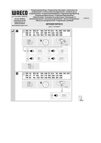
- The distance from the sensors to the ground should be at least 40 cm and a maximum of 50 cm (fig. 2).
- For the sensors to function optimally, the angle of the sensor to the road surface should be 90° (fig. 2). The angle may not be less than 90°, as the road will otherwise be interpreted by the sensor as an obstacle.
- The sensor holders included are suitable for all standard bumpers. Should the vehicle bumper be mounted at a steep angle, 20° sensor holders with a cover ring are available as an optional extra (see chapter “Accessories for WPS 900F/WPS 910” on page 29).
- The sensor holders included are not suitable for installation in metal bumpers. If your vehicle has metal bumpers, you will need special sensor holders with a silicon ring (see chapter “Accessories for WPS 900F/WPS 910” on page 29).
- Note that the sensor holder depends on the installation height and the angle of the bumper. Select the right sensor holder and the appropriate drill diameter by consulting the table in fig. 2. The instruction manual shows how to install the standard sensor holder (fitted from the inside of the bumper), which produces the best visual result. Alternatively, the sensors can also be fitted using the sensor holders with cover ring which are provided.
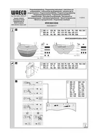
- Install the sensors in the correct position (fig. 5):
Colour of sensor Installation location
Blue (bl) Outer sides of the rear bumper
Black (sw) Middle sensors on the rear bumper
brown (br) Front bumper
4.3 Painting the sensors
See fig. 6

NOTE
The sensors may be painted. The manufacturer recommends having the sensors painted by a specialist workshop.
5 Fitting the parking aid

NOTICE!
On vehicles which feature metal reinforcement behind the bumpers, the sensors must not be touching this reinforcement. Otherwise there is no guarantee the parking aid will function correctly.
See fig. 7 to fig. 12
Supplements fig. 8

NOTICE! Risk of malfunction!
Align and attach the sensor holders correctly. Otherwise there is no guarantee the parking aid will function correctly.
The sensor holders must be attached with the retaining tabs pointing up and down.
▶Clean the adhesive surface on the inner side of the bumper with a primer.
▶Apply a small amount of grease inside the sensor plug connections.
Supplements fig. 11
Both the control electronics have been configured for front sensors by default. Define the control electronics for the rear sensors as follows:
▶Disconnect the cable bridges.
6 Connecting the parking aid

NOTE
- On some vehicles, the reversing light only works when the ignition is switched on. In this case, you must switch on the ignition in order to identify the positive and earth wires.
- You can set a switch-off time for the front system if you are unable to provide a speedometer signal for the front sensor control electronics (neither a digital connection via the CAN bus nor an analogue connection from the speedometer) (see chapter “Programming the system” on page 37 and fig. 19, parameter 1).
- You can connect the control electronics for the rear sensors directly to the continuous operating voltage or to the positive cable for the ignition (fig. 14) if you are unable to provide a reversing signal for the rear sensor control electronics (e.g. +12 V contact voltage from the reversing light). This is only an option if you use the CAN bus connection to the control unit, and the vehicle CAN bus provides the reversing signal (see vehicle-specific product overview on the WAECO homepage "http://www.dometic-waeco.de/wps900").
- A reversing signal is not provided via CAN bus on all vehicles which allow a CAN bus connection.
The complete circuit diagram can be found in:
- fig. 13 for reversing signal via reverse gear
- fig. 14 for reversing signal via CAN bus
No. Description
| 1 Control electronics for rear sensors |
| 2 Control electronics for front sensors |
| 3 Black/blue cable: connection to the reversing light |
| 4 Reversing light |
| 5 Brown cable: Connection to earth |
| 6 Black cable bridge (connected = front unit/disconnected = rear unit) |
| 7 Rear sensors |
| 8 Front sensors |
| 9 Brown cable: connection to the negative battery terminal. |
| 10 Black/blue cable: connection to the positive battery terminal. |
| 11 Yellow/black wire (for the front system only): Connection to earthOptional: connection to the speed signal from the speedometer |
| 12 Black/blue cable: connection to connected positive (+12 V) |
| 13 Black/red wire for the control unit: connection to the black/red wire of the external button |
| 14 External button |
| 15 Black wire from the external button: connection to earth |
| 16 Brown cable: connection to earth |
| 17 Orange/brown wire: connection to CAN Low |
| 18 Orange/green wire: connection to CAN High |
| 19 Control unit |
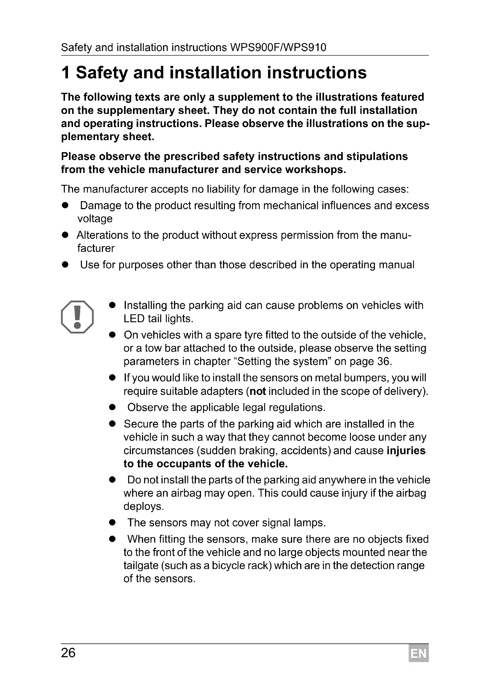
7 Detection range
See fig. 15
The detection range of the parking aid is divided into four zones (The figure applies accordingly for the front sensors):
- Zone 1
This zone is the first limit range. Small objects or those with poor reflective characteristics may not be detected here.
- Zone 2
Nearly all objects in this zone are displayed.
- Zone 3
Nearly all objects in this zone are displayed, however objects may only appear in the sensors' blind spot, or not be detected at all due to their consistency or small size.
- Stop zone (4)
If there are objects in this zone, the parking aid emits a continuous tone warning you to stop.
Nearly all objects in this zone are displayed, however objects may only appear in the sensors' blind spot or not be detected at all due to their consistency or small size.
The distance at which the parking aid starts signalling you to stop can be set to different levels.
The display of fixed objects, such as a trailer hitch, can be suppressed.
8 Setting the system

NOTICE!
Incorrect settings can impair the operational safety.

NOTE
To stop setting the parameters without saving your changes, or to stop the entire set-up: refrain from pressing any buttons for a while.
8.1 Control elements
The control unit features the following control elements:
| No. in fig. 16 Description |
| 1 Left button |
| 2 Red LED |
| 3 Yellow LED |
| 4 Right button |
| 5 Loudspeaker |
The external button features the following control elements:
| No. in fig. 16 Description | ||||||
| 6 | LED | |||||
| 7 | B | u | t | t | o | n |
8.2 Learning the system

NOTE
You must carry out the learning procedure within 4 minutes of activating the front sensors. Once these 4 minutes have elapsed, the front system will stop sending an ID code.
The system communicates by radio contact. The control unit must be programmed to ensure it recognises the codes from the other devices.
See fig. 17
Start the programming procedure as follows:
▶Connect the voltage supply for the front control electronics.
▶Switch on the ignition.
▶Engage the reverse gear.
▶ Press the left and right button on the control unit simultaneously for 5 seconds.
√ The loudspeaker will emit two tones and the red and yellow LEDs will light up twice.
▶Let go of the two buttons.
▶Wait for a high-pitched tone and for the yellow LED to light up.
▶ WPS910 only: Wait for a low-pitched tone and for the red LED to light up.
▶Wait for the loudspeaker to emit three tones and for the yellow and red LED to light up three times.
▶Switch the ignition off.
8.3 Programming the system

NOTE
Adapt the programming of the parameters to the type of installation you have carried out.
You can programme diverse settings.
See fig. 18
▶Start programming as follows:
- Switch on the ignition.
- Engage reverse gear.
- Press the left button on the control unit for 5 seconds.
The loudspeaker emits a peep tone once, and both LEDs light up.
▶ Set the preferred value (fig. 19; chapter “Programming functions” on page 39).
The right button of the remote control is used to set the tens, and the left button is used to set the units for the preferred value. For example, if you wish to set the function "24", press the right button twice and the left button four times.
▶Once you have set the desired value, wait until the loudspeaker beeps in accordance with the value you have set and the respective LED flashes accordingly.
▶Switch the ignition off.
Configuring the front sensors
The front parking aid is always activated when you:
- Switch on the ignition
- Engage the reverse gear (WPS910 only)
- Briefly press the right button on the loudspeaker (< 5 seconds)
- Press the external button (< 5 seconds)
Programming functions
You can also set the function for the front sensors by programming it once, using the following method, among others (see fig. 19):

NOTE
The default settings are printed in bold in the table fig. 19.
● Parameter 1: Speed signal/time-out front sensors (function 13 – 16)
Default setting: speed-dependent
Function 13 (speed-dependent) is set by default. If there is no speed signal available which is compatible, you have the alternative of using the time-out to deactivate the front parking aid. Once activated, the programmed time period starts counting down.
If there is an obstacle in the detection range when the time period is over, the front parking aid remains active. Only when no obstacle is detected for more than 5 s will the front parking aid shut down.
- Parameter 2: Duration of the front sensor signal Default setting: 1 sec.
- Parameter 3: Choose the speed signal source Default setting: Control unit
- Parameter 4: Detection range of the inner front sensors Default setting: 80 cm
- Parameter 5: Detection range of the inner rear sensors Default setting: 160 cm
- Parameter 6: Detection range of the outer front sensors Default setting: 55 cm
- Parameter 7: Detection range of the outer rear sensors Default setting: 55 cm
- Parameter 8: Stop zone for front sensors
Default setting: Corner sensors = 25 cm, middle sensors = 35 cm
● Parameter 9: Stop zone for rear sensors Default setting: 35 cm - Parameter 10: Volume of warning tones for front sensors Default setting: High
- Parameter 11: Volume of warning tones for rear sensors Default setting: High
- Parameter 12: Suppress display of fixed objects Default setting: Off
- Parameter 13: Shut-down delay for rear sensors Default setting: Off
- Parameter 14: Number of speed signal pulses Default setting: 3
- Parameter 15: CAN bus status Default setting: On
- Parameter 16: City function (function 66) or speed-dependent activation and deactivation (function 67)
Default setting: Speed-dependent activation and deactivation
Speed-dependent activation and deactivation (function 67)
The default setting automatically activates the front parking aid at speeds below 10 km/h and automatically deactivates at speeds above 10 km/h.
Connecting a compatible speed signal is essential for this function to work.
City function (function 66)
This function deactivates the front parking aid the first time a speed of 10 km/h is exceeded and does not activate it again when the speed falls below 10 km/h. It is only activated:
- the next time the reverse gear is engaged - when the right button on the loudspeaker is pressed - when the external button is pressed (< 5 s)
The next time the ignition is started, the initial 10 km/h limit is activated again.
Connecting a compatible speed signal is essential for this function.
This function is useful when, for example, the parking aid is considered a nuisance while driving in city traffic when roads are full, or in traffic jams.
● Parameter 17: Reset to default settings
9 Testing functions
Complete the functional test of the rear sensors as follows:
▶Switch on the ignition and engage the reverse gear.
Be very careful when you use the device for the first time, and make sure that you familiarize yourself with the various sequences of beeps (see fig. 15).

NOTICE!
In zone 4, some obstacles may not be detected, because they are no longer within range of the sensors (construction-related characteristic).
Test the front sensors the same way. To do so, drive slowly, for example, towards a wall.
10 Using the parking aid
The rear sensors are automatically activated when you engage the reverse gear when the ignition is on or the engine is running.
The front sensors are activated automatically:
- by starting the vehicle
● by engaging the reverse gear
● by lowering the vehicle speed to less than 10 km/h
● by pressing the right button on the control unit
● by pressing the external switch
When the front sensors are activated, the LED on the external button and the yellow LED on the control unit both light up.
If the speedometer signal cannot be detected, the front sensors are activated when the ignition is switched on. Once the adjustable switch-off time has elapsed, they are deactivated automatically.
As soon as there is an obstacle within the detection range, a steady signal tone is emitted repeatedly.
As you approach, the tone sequence will change according to the zone in which the obstacle is, thereby indicating the distance (fig. 15 applies to the front sensors).
Be very careful the first time you use the system, until you are familiar with the various sequences of beeps.
The front sensors are deactivated when
● the speed of the vehicle is more than 10 km/h
- you press the external button or the right button on the control unit briefly. Press one of the two buttons for at least 5 s to deactivate the front sensors until the next time the vehicle is started.

NOTICE!
Stop the vehicle immediately and investigate the situation (getting out if necessary), if the following happens while you are manoeuvring:
the device first indicates an obstacle and the tone sequence speeds up normally (e.g. from slow to medium) when manoeuvring. The signal tone suddenly slows down, or no obstacle is indicated at all.
This means that the original obstacle is in the blind spot of the sensors (construction-related characteristic), and there is still a potential for collision.

NOTICE!
Be especially careful when manoeuvring after the system has been disconnected from the front or rear sensors.
The system will indicate this fault by:
● the speaker will emit a double alarm tone.
- the red LED in the control unit and the LED on the external button flash continuously.

NOTE
When the stop zone is reached, the volume of the continuous tone will fall by about 50 % after a short time.
11 Troubleshooting
The device shows no function.
The cables to the reversing light are not connected or are not properly connected.
The plugs for the sensors are not connected or are not correctly plugged into the control electronics.
▶Check the plugs and make sure they lock into place.
The speaker emits a double alarm tone, and the red LED in the control unit and the LED on the external button flash continuously
The system has been disconnected from the front or rear sensors. This can occur due to interference in the frequency range. Reprogramme the control modules (see chapter “Learning the system” on page 37).
Audible error signal is emitted for three seconds after engaging the reverse gear, following by a sequence of tones.
One or more sensors are defective or no longer connected to the control electronics. The LEDs in the control unit and the LED on the external button are flashing rapidly. The sequence of tones following the continuous tone indicate which sensor is defective:
● high tones for the front sensors (e.g. two high tones for front sensor no. 2)
- low tones for the rear sensors (e.g. three deep tones for front sensor no. 3)
The sensor with the shortest cable is sensor no. 1, the one with the longest cable is sensor no. 4.
▶Check the plugs and make sure they lock into place.
▶Replace the defective sensor(s).

NOTICE!
The system does not work if one or more sensors are defective.
The front sensors shut down too early
The front sensors shut down before the speed reaches 10 km/h. The LEDs in the control unit and on the external button switch off.
▶Set parameter 14 (“number of speed signal pulses”) to function “59”, “61”, “62” or “63” (see chapter “Programming the system” on page 37).
Device indicates obstacles incorrectly
False alarms may have the following causes:
- Dirt or frost on the sensors
▶Clean the sensors. - Rain
▶ Check whether the front sensors are deactivated at a speed exceeding 10 km/h.
▶Check whether a compatible speed signal is available.
If there is no speed signal available, set parameter 1 (“Speed signal/Time-out front sensors”) to function “14”, “15” or “16” (see chapter “Programming the system” on page 37).
● The sensors were incorrectly installed.
▶ Adjust the position or height of the sensors (fig. 2).
▶Make sure that the appropriate sensor bracket was used (0°/12°/20°/bracket for metal bumpers).
● The sensors are in contact with the chassis.
▶Separate the sensors from the chassis.
No acoustic signal.
▶Check whether the yellow LED in the control unit and the LED on the external button light up.
When the LEDs are flashing, the system is in emergency mode. Start the vehicle again.
Objects on the vehicle (e.g. spare wheel) result in false alarms.
▶ Set parameter 12 (“Suppress display of fixed objects”) to function “52”, “53” or “54” (see chapter “Programming the system” on page 37).
12 Guarantee
The statutory warranty period applies. If the product is defective, please contact the manufacturer's branch in your country (see the back of the instruction manual for the addresses) or your retailer.
For repair and guarantee processing, please send the following items:
- Defect components
● A copy of the receipt with purchasing date
● A reason for the claim or description of the fault
13 Disposal
▶Place the packaging material in the appropriate recycling waste bins wherever possible.

If you wish to finally dispose of the product, ask your local recycling centre or specialist dealer for details about how to do this in accordance with the applicable disposal regulations.
14 Technical data
| MagicWatch WPS900F | MagicWatch WPS910 | |
| Item no. 9101500019 9101500020 | ||
| Detection rangeStop zone:Measuring range: | Approx. 0.1 m to 0.25 mApprox. 0.25 m to 0.9 m | Approx. 0.1 m to 0.3 mApprox. 0.3 m to 1.8 m |
| Ultrasound frequency: 40 kHz | ||
| Transmission frequency: 868 kHz | ||
| Supply voltage: 9–30 volts | ||
| Current consumptionOperating:Standby: | Max. 180 mA8.5 mA | Max. 240 mA8.5 mA |
| Operating temperature: -25 °C to +70 °C | ||
Certification: | ||

NOTE
The sensors may be painted. The manufacturer recommends having the sensors painted by a specialist workshop.
8 Stille inn systemet

PASS PÅ!
Dometic Australia Pty. Ltd.
1 John Duncan Court
Varsity Lakes QLD 4227
+61 7 55076000
+61 7 55076001
Mail: sales@dometic-waeco.com.au
AUSTRIA
Dometic Austria GmbH
The Gateway · 25 Canton Road,
Tsim Sha Tsui · Kowloon
Hong Kong
+852 24611386
吕 +852 24665553
Mail: info@dometic-waeco.com.hk
ITALY
Dometic Italy S.r.l.
Via Virgilio, 3
I-47100 Forll
+39 0543 754901
+39 0543 756631
Mail: info@dometic.it
NORWAY
Dometic Norway AS
Skolmar 24
N-3232 Sandefjord
+47 33428450
+47 33428459
Mail: firmapost@waeco.no
POLAND
Dometic Poland Sp. z o.o.
Ul. Puławska 435A
02-801 Warszawa
Poland
+48 22 414 32 00
+48 22 414 32 01
Mail: info@dometic.pl
RUSSIA
Dometic RUS LLC
Komsomolskaya square 6-1
107140 Moscow
Russia
+7 495 780 79 39
+7 495 916 56 53
Mail: info@dometic.ru
SLOVAKIA
Dometic Slovakia s.r.o.
Tehelná 8
SK-98601 Fil'akovo
+421 47 4319 107
+421 47 4319 166
Mail: info@dometic.sk
SPAIN
Dometic Spain S.L.
Avda. Sierra del Guadarrama, 16
E-28691 Villanueva de la Cañada
Madrid
+34 902 111 042
+34 900 100 245
Mail: info@dometic.es
SWEDEN
Dometic Scandinavia AB
Gustaf Melins gata 7
Dometic Switzerland AG
Riedackerstrasse 7a
CH-8153 Rümlang (Zürich)
+41 44 8187171
吕 +41 44 8187191
Mail: info@dometic-waeco.ch
TAIWAN
WAECO Impex Ltd.
Taipei Office
2 FL-3 · No. 56 Tunhua South Rd, Sec 2
Taipei 106, Taiwan
+886 2 27014090
+886 2 27060119
Mail: marketing@dometic-waeco.com.tw
UNITED KINGDOM
Dometic UK Ltd.
Dometic House · The Brewery
Blandford St. Mary
Dorset DT11 9LS
+44 844 626 0133
吕 +44 844 626 0143
Mail: sales@dometic.co.uk
UNITED ARAB STATES
Dometic Middle East FZCO
P. O. Box 17860
S-D 6, Jebel Ali Freezone
Dubai, United Arab Emirates
+971 4 883 3858
昌 +971 4 883 3868
Mail: info@dometic.ae
UNITED STATES OF AMERICA
Dometic Marine Division
2000 N. Andrews Ave. Extension
Pompano Beach, FL 33069 USA
+1 954 973 2477
+1 954 979 4414
Mail: marinesales@dometicusa.com