ML510EV - Garage door CHAMBERLAIN - Free user manual and instructions
Find the device manual for free ML510EV CHAMBERLAIN in PDF.
Frequently Asked Questions - ML510EV CHAMBERLAIN
User questions about ML510EV CHAMBERLAIN
0 question about this device. Answer the ones you know or ask your own.
Ask a new question about this device
Download the instructions for your Garage door in PDF format for free! Find your manual ML510EV - CHAMBERLAIN and take your electronic device back in hand. On this page are published all the documents necessary for the use of your device. ML510EV by CHAMBERLAIN.
USER MANUAL ML510EV CHAMBERLAIN
Manager, Regulatory Affairs
Chamberlain GmbH
Alfred-Nobel-Str. 4
D-66793 Saarwellingen
January 2013
Barbosa P. Keckhoft

1 General safety guidelines 2
2 Intended use 3
3 Scope of supply 3
4 Product overview 3
5 Before you begin 3
5.1 Preconditions 3
5.2 Preparation 3
5.3 Tools required 3
6Assembly of the door opener 3
6.1Assembling the rail 3
6.2 Tighten the chain 3
6.3 Fitting rail to the drive 4
7 Installation of the opener 4
7.1 Centre of the garage door 4
7.2 Mounting header bracket 4
7.3 Attaching drive to header 4
7.4 Hang opener 4
7.5 Mounting door bracket 4
7.6 Attaching door arm on the trolley 5
8 Electrical connection 5
8.1 Optional Accessories 5
8.2 Connecting the opener 5
9 Program opener and test 5
9.1 Adjust limits and force 5
9.2 Test the Safety Reverse System 5
9.3 Program another remote control 6
10 Operation of the door opener 6
11 Cleaning and maintenance 6
11.1 Cleaning 6
11.2 Maintenance 6
11.3 Replace batteries of the remote control 7
12 Replacing operator light 7
13 Disposal 7
14 Frequently asked questions 7-8
15 Specifications 9
16 Spare parts / Warranty 9
17 Accessory (optional) 9
18 Declaration of conformity 9
1 General safety guidelines
Before you begin the installation:
Please read the operating instructions and especially the precautions. Keep the manual for future reference and pass it on to a possible subsequent owner.
The following symbols are placed in front of instructions to avoid personal injury or property damage. Read these instructions carefully.

CAUTION
Personal injury or property damage

CAUTION
Danger due to electric current or voltage
Important safety information
The automated door opening system has been as a matter of course tested and designed for safe operation, but safety can be assured only if the safety instructions listed below are strictly adhered to during installation and operation.
Store these instructions without fail.
- The door should be balanced. Unmoving or stuck doors must be repaired. In an unbalanced state, garage doors, door springs, cables, discs, brackets and rails are under extreme tension, which can lead to serious injury. Do not attempt to loosen, move or realign the door, but contact service centre or a door specialist.
- During the installation or maintenance of a door opener, no jewellery, watches or loose clothing should be worn.
- To avoid serious personal injury due to entanglement, remove all cables and chains connected to the door before installing the door opener.
- During installation and electrical connection, the local building and electrical regulations must be observed. This device complies with Protection Class 2 and does not require grounding.
- To avoid damage to very light doors (such as fibre glass, aluminium or steel doors), an appropriate reinforcement should be added.
To do so, contact the door manufacturer.
The automatic safety reverse system should undergo a test. Upon contact with a 50~mm high barrier on the ground, the garage door MUST return. Failure to properly adjust the door opener can result in serious personal injury from a closing garage door. Repeat test once a month and make any needed changes. - This system must not be installed in damp or wet areas.
- During operation, the gate should not under any circumstances obstruct public passageways.
- To remind all operators of the safe operation, in addition to the illuminated wall switch a warning sign to protect children should be affixed. The warning signs about the risk of trapping should be placed in clearly visible spots.
- Children should be supervised to ensure that they do not play with the device.
This device is not intended for use by persons (including children) with restricted physical, sensory or mental abilities or lack of experience and/or knowledge, unless they are supervised by a person responsible for their safety or have received instruction in how to use the device. - All barriers / locks are deactivated to avoid damage to the door.
If necessary, installed control equipment MUST be mounted within sight of the door and out of reach of children. Children should not be allowed to operate the buttons or remote controls. Misuse of the door opener can result in serious injury. - The door opener should ONLY be used if the operator can see the entire door area and is assured that it is free of obstacles and the door opener is set correctly. No one may pass through the door while it is moving. Children must not be allowed to play in the vicinity of the door.
- Use the manual release only for the separation of the carriage from the drive and - if possible - ONLY with the door closed. Do not use the red handle to push the door up or pull it down.
- Before performing any repairs or removing covers, the door opener should be separated from the electric power supply.
- This product has a transformer with a special cable. In case of damage this MUST be replaced with an original transformer by a qualified technician.
Operation of the emergency release can lead to uncontrolled movements of the door, if springs are weak or broken or if the door is unbalanced. - Mount the release handle of the emergency release at a height of at least 1.80m
2 Ir.tended use
The device is intended for the opening and closing of tilt-up and sectional garage doors in the private sector. The device is not meant for commercial use but solely for the use in private garage doors that are appropriate for a single household.
Any improper use of the drive could increase the risk of accidents.
The manufacturer assumes no liability for such usage.
3 Scope of supply
Please check the supplied parts for completeness before starting the installation.
Note: The numbering only applies to the corresponding section.
Parts overview:
-
Door fixture 1x
-
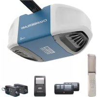
Drive head 1x
- Accessories bag 1x
- Handheld transmitter 2x
9.Rail 1x
3.Curved door arm 1x - Support bracket 2x
- Mounting bracket 3x
- Header bracket 1x
Hardwarebag:
-
Truss head screw
-
Safety cotter pin 1x
This figure always offers you a complete overview of the ready-assembled system during the step by step installation of the system.
-
Header bracket
-
Power cable
-
Chain
-
Drive head
3.Rail
-
Release
-
Carriage
-
Straight door arm
-
Connecting piece
-
Curved door arm
-
Mounting bracket
-
Door bracket
-
Support bracket
5 Before you begin
IMPORTANT NOTE
If your garage does not have a side entrance, an external emergency release should be installed. This allows for manual operation of the garage door from the outside during power failure.
5.1 Preconditions
The garage door opener is suitable only for installation in one-piece garage doors with horizontal guide rail (tilt-up door) (Fig. A) and in sectional doors with curved guide rail (Fig. B).
NOTE:
The system cannot be used for one-piece garage doors with horizontal and vertical guide rails and two-wing doors or overhead doors.
Preparation
First, check whether your door is balanced and in equilibrium. Open your door about halfway and let it go.
The door can now hardly change its position independently, but must remain in this position held by the spring force alone.
Motive force: maximum 15 kg.
- The rail of the garage door MUST be connected securely and firmly to the supporting wall or ceiling above the garage door.
- Additional brackets and mounting rails (not included in the supply) might be required, if the your garage ceiling has a cladding, boards or similar.
- If your garage does not have a separate side entrance, an external emergency release should be installed.
5.3 Tools required
Tool list:
Hacksaw
Ladder
Different drill bits
Marking pen
(8,6,5,4.5 mm)
Pliers
Box wrench
Drilling machine
Water level
Hammer
Screwdriver
Ratchet
Measuring tape
Assembly of the door opener

Important instructions for a safe installation.
Observe all assembly instructions.
Incorrect installation can cause serious injury.
6.1 Assembling the rail
The rail is largely preassembled and consists of 3 parts. The carriage, push rod, release handle, the guide pulley and the lintel bracket with chain tensioner are in the front part (A). The seating for the drive shaft and the sprocket are in the rear part (B). Lay the front and rear rail sections one behind the other.
-
Remove cable ties that secure the chain. Leave the transport lock (X) still in position.
-
Pull apart the two rail sections completely in order to create a gap for the middle section (C). This rail is designed in such a way so as to easily add the middle section. Slide the 2 connecting pieces (D) over the seams of the rail sections up to the markings. To secure the connecting pieces, bend the sheet metal lugs out-wards with a suitable tool.
The assembly of the rail is complete.
6.2 Tighten the chain
Tighten the chain of the rail until the spring (1) is compressed only by about half.
This must be able to bounce during operation.
6.3 Fitting rail to the drive
- Remove transport lock (X). Check if the chain is seated on the gearwheel. If the chain has slipped off during assembly, relax the chain, lay it and tighten again.
- Turn around the rail (1) and completely put on the opener (3) with the gear side (2).
- Secure the rail on the opener with two mounting brackets (4) and the screws (5).
This completes the assembly of the door opener.
7 Installation of the opener
7.1 Centre of the garage door
Eye protection goggles should be worn for overhead work. All available barriers / locks should be deactivated to avoid damage to the door.
To avoid serious injuries, remove all cables and chains connected to the door before installing the door opener. The door opener should be mounted at a height of at least 2.10m above the ground.
First, mark the centre line of the door (1). Draw a line to the ceiling starting from this point.
For installation on the ceiling, draw another line to the centre of the ceiling (2) perpendicular to the door starting from this line. Length approx. 2.80m .
7.2 Mounting header bracket
NOTE: Mount the rail max. 50mm above the top edge of the door. Depending on the door type, the top edge of the door is lifted by a few cm during opening.
A. Wall fastening:
Minimum space requirement above the door: 100mm
Mount header bracket (1) centrally on the vertical centre line (2); thereby its lower edge lies on the horizontal line. Mark all holes for the header bracket. Pre-drill holes with 4.5mm diameter and fasten the header bracket with wood screws (3).
NOTE:
In case of mounting on a concrete slab / concrete header, the provided concrete plugs (4) and screws (3) should be used. Drill hole size in concrete: 8 mm.
B. Ceiling suspension:
Minimum space requirement above the door: 35mm
Draw vertical centre line (2) further up to the ceiling and about 200mm along the ceiling. Attach header bracket (1) centrally on the vertical marking up to 150mm removed from the wall. Mark all holes for the header bracket. Drill holes with 4.5mm diameter and fasten the header bracket with wood screws (3).
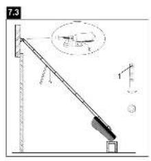
7.3 Attaching drive to header

It may be necessary to place the drive temporarily higher, so that the rail does not hit the springs in multi-piece doors. The drive must either be well supported (ladder) or held firmly
by a second person.
Put drive head on garage floor under the lintel bracket.
Lift rail up till the holes of the fixing part and the holes of the lintel bracket are aligned.
Insert screw (1) through the holes and secure with nut.
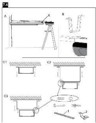
7.4 Hang opener
- Fully open the door, put down door opener on the door (Fig. A). Lay a piece of wood / cardboard on the marked spot (X).
- The mounting bracket must be mounted so far back that the carriage is not obstructed. The carriage can pass through below the bracket partially, but not the door arm. Mounting at the very back (Fig. B) is ideal.
- Bend ceiling fixtures (1) in such a way that they lie flat against the ceiling. Depending on how large the distance to the ceiling is, none, one or two of the support brackets are to be mounted (Fig. C1, C2 and C3).
- Mark the boreholes on the ceiling. Pay attention to the same lateral distance along the drawn centre line in each case.
- For concrete ceilings, boreholes with 8mm diameter are drilled into the ceiling and dowels used. Then, the ceiling fixtures are fastened in the ceiling with hexagon wood screws. While mounting on the wooden ceiling: fasten only on the supporting parts of the wooden ceiling. Drill boreholes with 4mm diameter and use hexagon wood screws.
- Place mounting bracket (2) around the rail, then align to the ceiling fixture and bolt them together.

Pay attention to a horizontal course of the rail along the ceiling. The distance can be adjusted by the given hole spacing. Protruding ends of the ceiling fixture can be reduced
if necessary.
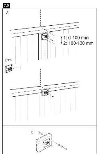
7.5 Mounting door bracket
Installation in sectional or one-piece doors:
The door bracket (1) has multiple mounting holes. Attach door bracket top centre on the inside of the door as shown. Mark holes and screw door bracket.
Mounting heights:
- One-piece or sectional door with a guide rail: distance to door top edge 0-100 mm.
- Sectional door with two guide rails: instance to door top edge 100-130 mm.
NOTE:
The attachment point on the door must be the frame or a stable place on the door panel. If necessary, drill through and screw (not included) together as shown in Fig. B.
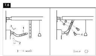
7.6 Attaching door arm on the trolley
The straight door arm is already pre-assembled.
Recommended installation:
The trolley can be separated from the drive by pulling the red handle and manually pushing towards the door. When the door is closed, fix the curved door arm (1) on the door bracket with the bolt (2) and secure with cotter pin (3). Connect straight and curved door arms together flush with an overlap of 2 holes with screw (4) and secure with nut (5). Choose the holes in such a way that the door arm stands at an angle of about 30 - 40^ .
NOTE:
The curved door arm can be omitted, if the door fitting has been attached at the far upper edge of the door.

Mount the release handle of the emergency release at a height of at least 1.80m
Attach the yellow label regarding the release of the garage
door opener (sticker) on the cord of the door handle.
8 Electrical connection

In order to avoid personal injury and damage to the device, the door opener should be operated only if such an instruction is explicitly stated in this manual. The power plug must
always be freely accessible for the purpose of disconnecting the mains supply.
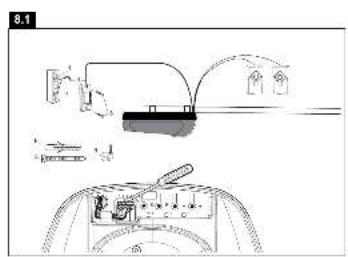
8.1 Optional accessories
Installation of photocells
After installing and adjusting the door opener, photocells can be installed (terminals 2 + 3 ). The installation instructions are included with the photocells.
The optional photocells ensure that the door is open, or remains open, if people, especially young children, are in the door area. By means of the photocells, a closing door is opened or an open door is obstructed from closing, if a person located in the door area interrupts the sensor beam.
Photocells are particularly recommended for families with young children.
Connecting the illuminated push button

All wall-mounted switches or buttons should be installed in sight of the door outside the door or door rail area at a height of 1.5 metres. In addition to these switches, the warning sign for the protection of children should be affixed
On the back of the push button there are two screw terminals
(1 & 2). The insulation is stripped up to about 6mm from the bell wire (4). Pull apart wires far enough from each other so that it is possible to connect the white/red wire to a screw terminal (1) and the white wire to the other screw terminal (2).
Illuminated wall switch: Mount on an inner wall of the garage using the supplied sheet metal screws (3). For dry or concrete walls, pre-drill holes with 5mm diameter and use dowels. It is recommended to undertake the assembly next to the garage side entrance out of reach of children. Tighten both screws carefully and do not tighten too much to avoid damaging the plastic housing. Run the bell wire along the wall over the ceiling up to the door opener. Attach the wire using nailing clips. Run bell wire from the top through the cable duct to the terminal.
The terminals are located in the recess next to the programming switches. Connect bell wire to the terminals 1 + 2
8.2 Connecting the opener
Connect opener in accordance with local rules and regulations to a properly installed earthed wall socket.
NOTE:
When the opener is switched on, the operator light is also turned on briefly.
9 Program opener and test

The door opener should only be used if the operator can see the entire door area and is assured that it is free of obstacles and the door opener is set correctly. No one may pass through
the door while it is moving. Before the first opening operation, check that all the facilities that are not needed are turned off. Remove all mounting aids and tools from the pivot area of the door.
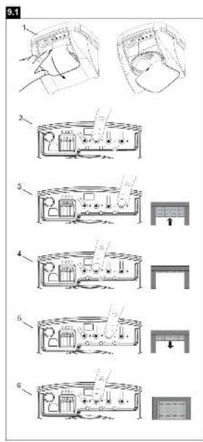
9.1 Adjust limits and force
- Open light cover.
- Press ^nP " and hold it until LED3 starts flashing (1).
- Press n + ^n and hold it until the door is completely open (2). If necessary adjust using n - ^n .
- Press ^nP^n briefly,LED2 starts to glow (3).
- Press "−" and hold it until the door is completely closed. The rail must not bend up (4). If necessary adjust using "+"
- Press "P" again briefly. The drive now automatically opens the door completely and then closes the door completely (5). During this process the force required by the opener is set.
NOTES:
Do not interrupt the opener during this process otherwise you have to repeat the whole procedure. In case the door pushes against the door frame and reverses, the „closed“ limit hasn't been set properly.
Repeat limit setting and make sure the rail doesn't bend when setting the closed limit.
Force adjustment:
Possibility 1: When installing the opener the travel (distance between the Open and Closed position) and the optimal pulling force is learned.
Possibility 2: Cut the opener from mains supply for approx.
10 seconds. Then open and close the door via remote control or wall switch.
NOTE:
Before any modification to the force adjustment check the door for proper functioning.
The opener is no support for a malfunctioning door. You can check proper functioning by releasing the opener and opening and closing the door manually.
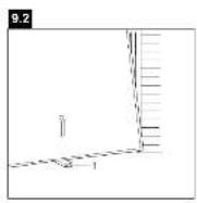
9.2 Test the Safety Reverse System

The safety reverse system test is important. Garage door must reverse on contact with a 50~mm obstacle laid flat on the floor. Failure to properly adjust opener may result
in serious personal injury from a closing garage door. Repeat test once a month and adjust as needed.
OBSCTACLE TEST:
Place a 50~mm high obstacle (1) under the garage door on the floor. Move door downwards. The door must reverse when it comes into contact with the obstacle. If upon contact the door stops, the door does not move down far enough. In this case repeat limit setting (see 9.1).
If the door reverses after contact with the 50~mm high obstacle, remove obstacles and open and close the door completely once
The door should not go back, if it reaches the door position "Closed". If it still reverses both limits must be reprogrammed (see 9.1).
OPENING TEST: Apply 20kg to the middle of the door.
The door should not open.
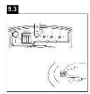
9.3 Program another remote control
The supplied remote control is already programmed.
When purchasing additional remote controls, program the receiver to match the additional remote control codes.
Program:
- Press "S" for 1-2 seconds. LED1 begins to glow (for approx. 10 seconds).
- Briefly press a button of the remote control twice.
- LED1 goes out. The Code is programmed.
NOTE: Only one of the two buttons can be programmed.
The last programmed button functions.
Delete:
All programmed remote control codes will be deleted. Press ,S" and hold it until LED1 goes out (approx. 8 seconds). All programmed codes are now erased. Reprogram each remote control you wish to use.
NOTE: Only the original remote controls from the manufacturer should be used. Remote controls that may look very similar, but do not originate from the manufacturer are not compatible. Such third-party remotes create malfunctions such as automatic opening, and the guarantee on the function and safety expires.
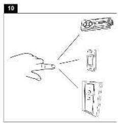
10 Operation of the door opener
Automatic opening / closing of the door:
The door opener can be operated using the following devices:
- Handheld transmitter: Press the button until the door starts to move.
- Wall switch (if this accessory is installed): Press the pushbutton until the door starts to move.
- External key switch or wireless keypad (if this optional accessory is installed).
Manual opening of the door (by hand):

If possible, the door must be closed completely. Weak or defective springs can cause a rapid shutting down of the opendoor, which can lead to property damage or serious
personal injury.
RELEASE: Briefly turn the red handle down. Then open the door by hand. Open close door without pulling the cable!
LOCK: With the next upward or downward movement, it is automatically locked again.
Function sequence:
When operating the door opener by radio control or wall switch:
- closes the door when it is fully open,
- opens the door when it is fully closed,
- stops the door if it opening or closing,
- the door moves in the opposite direction to the last completed move, if it is partially open,
- drives back the door to the open door position, if it hits an obstruction while closing,
- stops the door, if it encounters an obstacle during opening.
- Light barrier (optional): By means of the light barrier, a closing door is lifted up or an open door is obstructed while closing, if a person located in the door area interrupts the sensor beam.
The operator light switches on in the following cases:
- First turning on of the door opener (short)
- Power interruption (short)
- With each turning on of the door opener.
The light turns off automatically after 2 1/2 minutes.
11 Cleaning and maintenance

Before any maintenance, cleaning and related maintenance work, the mains supply plug should be pulled out. Danger from electric shock!
Maintenance of the door opener
A proper installation ensures the optimum performance of the door opener with minimum maintenance. An additional lubrication is not required. Gross dirt accumulation in the guide rail may impair the function and must be removed.
11.1 Cleaning
Clean the drive head, wall switch and handheld transmitter with a soft, dry cloth.
Do not use liquids.
11.2 Maintenance

Check the system often, especially cables, springs and fasteners, for signs of wear, damage or lack of balance.
Do not use if repair or adjustment work must be performed, be
cause an error in the system or an incorrectly balanced door may cause injury.
Once a month:
- Check automatic safety reverse again and reset if necessary.
- Operate door manually. If the door is unbalanced or stuck, please contact the service centre.
- Check for complete opening and closing of the door. Where appropriate, readjust limit switches and / or power.
Twice a year:
- Check the chain tension. For this, first disconnect the carriage from the drive. If necessary, adjust chain tension.
- Lightly lubricate the guide rail with standard grease (lubrication).
Once a year (at the door):
- Lubricate door roller, bearings and joints. An additional lubrication of the door opener is not required.
Do not grease the door rails!
Limit switch adjustment and force regulation:
These settings must be checked and undertaken properly during the installation of the opener. Due to weathering, minor changes can occur during operation of the opener that need to be addressed by a new setting. This can particularly happen in the first year of operation.
Follow the instructions for setting limit switches and traction (see 9.1) carefully and re-check the automatic safety reverse after each resetting.
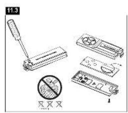
11.3 Replace batteries of the remote control
Battery of the remote control:
The batteries in the remote have an extremely long life. If the transmission range decreases, the batteries must be replaced.
Batteries are not covered by the guarantee.
Please observe the following instructions for battery:
Batteries should not be treated as household waste.
All consumers are required by law to dispose of batteries properly at the designated collection points.
Never recharge batteries that are not meant to be recharged.
Danger of explosion!
Keep batteries away from children, do not short-circuit them or take them apart.
See a doctor immediately, if a battery is swallowed.
If necessary, clean contacts on battery and devices before loading.
Remove exhausted batteries from the device immediately! Increased risk of leakage!
Never expose batteries to excessive heat such as sunshine, fire or the like!
There is increased risk of leakage!
Avoid contact with skin, eyes and mucous membranes. Rinse the parts affected by battery acid with plenty of cold water and consult a doctor immediately.
Always replace all batteries at the same time.
Use only batteries of the same type; do not use different types or mix used and new batteries.
Remove the batteries if the device is not being used for a long time.
Replacing battery:
To replace battery, turn remote control around and open the case with a screwdriver. Lift cover and lift control board below. Slide battery to one side and remove. Watch polarity of battery!
Assemble again from in reverse direction.
ATTENTION!
Danger of explosion if battery is replaced improperly.
Replacement only by identical or equivalent type (order 10A12-WH).
12 Replace operator light
The LED lighting has a very long life and is maintenance free.
Replacement and assembly:
- Unplug mains supply
- To replace the LED base, remove the opener's cover panel (detach 2 screws in the panel).
- Pull out plug of the LED base from the controller.
- Remove both screws on the panel beside the LEDs and detach the base.
- Reassemble in reverse order.
13 Waste disposal
The packaging is made from environmentally friendly materials. It can be disposed of in the local recycling bin. According to the European Directive 2002/96/EC on waste electrical and electronic equipment, this device must be properly disposed of after use to ensure the reuse of materials. The information on the possibilities of this waste disposal is provided by the local government or municipality.
14 Frequently asked questions
1. Door opener doesn't work with remote control:
- Is the opener connected to the power supply? If a lamp connected to the power socket does not turn on, check fuse or circuit breaker. (Some sockets are enabled via a wall switch).
- Are all door locks disabled?
See safety instructions!
- Does the control LED on the transmitter light up when the button is pressed? If not, either the battery is empty, or the transmitter is defective or too far removed from the opener.
Try operating with a new battery. - If you have two or more transmitters, of which only one works, check programming of the receiver.
- Is there snow / ice under the door? If yes, the door may be frozen onto the ground. Remove all obstacles.
- Perhaps the door spring is defective. This must be replaced by a specialist.
2. Transmission range of the device is too low:
Is a battery inserted? Put a new battery.
Try radio control in the car at another location.
- The transmission range diminishes for metal doors, aluminium or metal panels.
3. Door reverses for no apparent reason:
- Is the door hindered by anything? Pull manual release and operate door by hand. In case of unbalanced or stuck gate, please contact the service department.
- Re-programme operating power and stretch of way of the opener.
- Clear ice or snow in the closing area of the door.
- If the door reverses upon reaching the door position 'Closed', the limit switch must be set for this door position.
After completing every setting, the automatic safety reverse must be checked again:
- An occasional resetting of the end positions is not unusual. In particular, the weathering can shift the doorway.
4. The garage door opens and closes by itself:
- Delete all transmitters and then re-programme them. See „Programming of other handheld transmitters".
- Is the remote control button jammed in position „ON“?
- Use only original remote controls! The use of third-party products leads to disturbances.
- The remote control button was pressed accidentally (pocket).
- Cable of the wall switch is damaged (remove for testing purposes).
An accessory connected to the opener causes the drive (remove for testing purposes).
5. Door does not close completely:
- Re-programme stretch of way of the opener. Check for alterations in the mechanical components, e.g. door arms and fittings.
After each new setting of the door position 'Closed', the automatic safety reverse should be checked for function.
6. The door opens, but does not close:
- If installed, the light barrier should be checked. If the LED at the light barrier blinks, the alignment should be checked.
- Check transmitter or wall switch for function.
7. Operator light doesn't turn on:
- Open or close door. The light remains switched on for 2.5 minutes.
- Disconnect opener from the mains and connect again. The light comes on for a few seconds.
No power.
8. Operator light doesn't turn off:
- Disconnect the power from the mains supply for a short time and try again.
The 2.5 minutes are not yet over.
9. Motor hums and runs very briefly, but does not function:
- Garage door springs are defective. Close the door and disconnect from the opener by pulling on the handle of the carriage (manual release). Open and close door manually. If the door is properly balanced, it is held at each point of the doorway by the door springs alone. If this is not the case, contact your service centre.
- If this problem appears during the first use, the door may be locked. Deactivate door lock.
- Release opener from the door and try without door. If the door is fine, re-programme operating force and stretch of way.
10. Opener works only in one direction:
- Door springs may be defective or the door is stiff in one direction.
- If the door is fine, re-programme operating power and stretch of way of the opener.
11. The chain rattles on the rail:
- Adjust the chain tension. The cause is usually a very tight chain. The spring on the clamping device of the rail must not be compressed completely.
- The door runs unevenly and makes the drive vibrate. Improve door run.
12. Opener will not start due to power failure:
- Disconnect from the opener by pulling on the handle on the carriage (manual release). The door can now be manually opened and closed. If the opener is re-activated, the carriage also gets re-connected.
- If installed, the carriage is detached from the drive in case of power failure by an external emergency release from outside the garage.
13. Door reverses after the force was programmed:
- See if the rail bends. The opener requires a lot of power to move the door. Repair or install door correctly.
- Door is very heavy or in poor condition. Call a specialist.
14. Rail bends on the opener:
- Door is heavy, very heavy, stiff or in poor condition. Call a specialist.
- A swing of the rail while moving is a sign of an unevenly functioning door with constantly changing power requirements. Call specialist, possibly lubricate door. An additional suspension on the rail can be a remedy.
15. The opener „runs“ (audible turning of motor) but the carriage does not move:
The carriage is released from the opener.
- In a new installation: During the assembly of motor and rail, the pre-assembled adapter sleeve between the motor shaft and the rail was not installed. This sleeve is pre-assembled at factory, but can be removed. Standing behind the opener it can be observed whether the gearwheel turns in the rail or just the motor.
- In a new installation: The chain has come off from the gearwheel in the rail. Standing behind the opener, you can see the gearwheel.
- After years of use: Is the release defective or continuously disengaged?
After years of use: The sleeve between rail and motor or the motor control gear is defective.
16. The door releases by itself from the carriage and stops:
- An external release that has been installed during a power failure should be checked whether it stretches and releases during the opening of the door. Watch the mechanism and reset if necessary.
- The handle of the release mechanism should not get caught in other items.
17. The running path cannot be programmed, is de-programmed or is changing slowly:
- The programmed running path is too short. Programme a longer path for testing purposes.
- A small plastic knob is factory-mounted on the chain that is running in the rail. During the travel of the opener this little button must press the small switch located on the drive head. If the path is too short or the button was torn down by incorrect installation, it has to be fixed again. If the small switch is not pressed, the programming of the opener is not possible.
- A mechanical fault at the door due to deflected joints or the chain tension on the drive is too loose.
18.Description of LEDs
LED1
- Flashes briefly: A radio signal is received. Once the remote control is programmed it opens and closes the opener.
- Is constantly on for approx. 10 seconds: An additional remote can be programmed or all remotes will be deleted.
LED2
- Is constantly on: as long as the opener runs.
- Flashes: opener is in programming mode, "OPEN" position has already been programmed and opener is ready for position "CLOSED".
LED3
- Flashes: opener is in programming mode and ready for _OPENa position
15 Specifications
Input voltage 230-240 V 50 Hz
Max. pulling force 500 N
Power 80 Watt
Nominal torque 3.0Nm
Standby consumption 0,8 Watt
Input accessories 24V / 300mA
Length of travel 2.63m
Speed
10
cm/sec
Lighting LED 1W
Safety
Electronically
automatic force adjustment
Electrically
thermal fuse in transformer
Limit switch adjustment
manually
Dimensions
Length (overall)
3.14 m
Required clearance height
min. 35 mm
Suspended weight
10 kg
Radio receiver
Memory
16 remote controls
Operating frequency
433 MHz, 868 MHz
Battery
3 V, type CR2032 (10A20-WH)
16 Spare parts / Warranty
Please refer to www.chamberlain.eu or contact your local dealer. Also refer to the available Warranty Book.
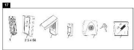
17 Accessory (optional)
- TX4RUNI
4-channel remote control
2.128REV
2-channel wireless wall control
3.747REV
keypad
4.75REV
illuminated push button
5.771REV
safety photocells
(Door reverses automatically without touching an obstacle)
6.1REV
external quick release
18 Declaration of conformity
Declaration of conformity
The listed automatic garage door opener corresponds to the applicable sections of the standards EN 55014-1 (2006), EN 55014-2 (2008), EN 61000-4-2 (2009), EN 61000-4-3 (2008), EN 61000-4-4 (2004), EN 61000-4-5 (2007), EN 61000-4-6 (2009), EN 61000-4-11 (2004), EN 62233 (2008), EN 300220-1 (V2.3.1), EN 300220-2 (V2.1.2), EN 60335-1 (2010), EN 60335-2-95 (2004) in accordance with the provisions and all amendments to the European Directives 2004/108/EC, 2006/95/EC, 2006/42/EC and 1999/5/EC.
Model: ML510EV
S./N: .xxxx000001 -xxxx99999
ManufacturerChamberlain GmbH
Alfred-Nobel-Str. 4
D-66793 Saarwellingen
All technical archive data for the opener and the associated accessories are kept safe by Chamberlain GmbH and will be provided to the authorities on request if required.
Barbara P. Kelkhoff

Manager, Regulatory Affairs
Chamberlain GmbH
Alfred-Nobel-Str. 4
D-66793 Saarwellingen
January 2013

Echelle Differents forets
ESSAI AVEC OBSTACLE:
Manager, Regulatory Affairs
Chamberlain GmbH
Alfred-Nobel-Str. 4
D-66793 Saarwellingen
January 2013
Banaa P. KeckhoH
C
Manager, Regulatory Affairs
Chamberlain GmbH
Alfred-Nobel-Str. 4
D-66793 Saarwellingen
January 2013
Babaa P. Keckhoft
C
Markeringsblyant (8, 6, 5, 4.5 mm)
Tang Stjernenogle
Boremaskine Vaterpas
Hammer Skruetraekker
Manager, Regulatory Affairs
Chamberlain GmbH
Aflred-Nobel-Str. 4
D-66793 Saarwellingen
January 2013
Dabaa P. KeckhoH
C E
Manager, Regulatory Affairs
Chamberlain GmbH
Alfred-Nobel-Str. 4
D-66793 Saarwellingen
January 2013
Babaa P. KeckhoH

1 Allmanna sakerhetsanvisningar 2
2 Aandamalsenlig anvanding 3
3 Leveransomfattning 3
4 Produktoversikt 3
5 Innan du bocrar 3
5.1 Forutsattninger 3
5.2Forberedelse 3
5.3 Nodvandiga verktyg 3
6Montera portens drivenhet 3
6.1Montera ihop skenan 3
6.2 Spänna kedjan 3
6.3Montera skenan pa drivenheten 4
7Montera in portens drivenhet 4
7.1Faststalla garageportens mitt 4
7.2Montera overstyckets feste 4
7.3 Fasta drivenheden pa overstycket 4
7.4 Hängauppportensdrivenhet 4
7.5Montera portens feste 4
7.6 Fasta portarmen pa Iopvangen 5
8 Elanslutting 5
8.1 Valfritt tillbehör 5
8.2 Ansluta drivenheten 5
9 Stalla in och testa porten 5
9.1 Stalla in andlagen och dragkraft 5
9.2 Testa automatisk sakerhetsreturledning 5
9.3Programmeraytterligarehandsandare 6
10 Manovrera portens drivenhet 6
11 Rengoring och underhall 6
11.1 Rengoring 6
11.2 Underhall 6
11.3 Byta handsandarens batteri 7
12 Byta drivenhetens belysning 7
13 Avfallschantering 7
14 Ofta stalda fragor 7-8
15 Tekniska data 9
16 Reservdilar/Garanti 9
17 Tillbehör (valfritt) 9
18 Forsakran om overensstammelse 9
LÄS FÜRST IGENOM FÖLJANDE SÄKERHETSANVISNINGARI!
1 Allmanna sakerhetsanvisningar
Innan monteringen paborjas:
Montera in portens drivenhet
Manager, Regulatory Affairs
Chamberlain GmbH
Alfred-Nobel-Str. 4
D-66793 Saarwellingen
January 2013
Babana P. Keckhoft
C
Manager, Regulatory Affairs
Dabaa P. KeckhoH
C
Chamberlain GmbH
Alfred-Nobel-Str. 4
D-66793 Saarwellingen
January 2013
Manager, Regulatory Affairs
Chamberlain GmbH
Alfred-Nobel-Str. 4
D-66793 Saarwellingen
January 2013


Ta navodila obvezno shranite.
2004/108/EGS, 2006/95/EGS, 2006/42/EGS in
1999/5/EU.:
Modell: ML510EV
S./N.: xxxx00001 - xxxx9999
Proizvajalec: Chamberlain GmbH
Alfred-Nobel-Str. 4
D-66793 Saarwellingen
Vse tehnicne arhivske podatke za pigeon in
ustrezen pribor hrani Chamberlain GmbH in ga
Manager, Regulatory Affairs
Chamberlain GmbH
Alfred-Nobel-Str. 4
D-66793 Saarwellingen
January 2013
Baalbana P. Keckhoh
C
8.Vite ST6.3 x 18mm 8x
A Anything.
A Anything.
A Anything.
A Anything.
A Anything.
A Anything.
A Anything.
A Anything.
A Anything.
A Anything.
Manager, Regulatory Affairs
Chamberlain GmbH
Alfred-Nobel-Str. 4
D-66793 Saarwellingen
January 2013
Babbaa P. Keckhoft
C
9.1 Regular as posicaoes finals e a forca de truncacao
Manager, Regulatory Affairs
Chamberlain GmbH
Alfred-Nobel-Str. 4
D-66793 Saarwellingen
January 2013
Barbana P. Keckhohff
C
Manager, Regulatory Affairs
Chamberlain GmbH
Alfred-Nobel-Str. 4
D-66793 Saarwellingen
January 2013
Dabbaa P. Kekkohff
C
Manager, Regulatory Affairs Chamberlain GmbH
Alfred-Nobel-Str. 4
D-66793 Saarwellingen
January 2013


Manager, Regulatory Affairs
Chamberlain GmbH
Alfred-Nobel-Str. 4
D-66793 Saarwellingen
January 2013
Barbana P. Keckhohff
C
Manager, Regulatory Affairs Chamberlain GmbH
Alfred-Nobel-Str. 4
D-66793 Saarwellingen
January 2013
Barbanna P. Keckhohff
C
1 Obiue npabina Tehnki 6e0nacnoctn 2
2IcnoJIb3OBAHnE no Ha3NaueHnIO 3
3 Komnlekt noctabkn 3
4Ob3op n3delen 3
5IpeedHaayamOMMOHTaKa 3
5.1 PpeBapntbIe ycnoBna 3
5.2 Podrotobka 3
5.3 Heobxodmbin Hnctpymert 3
6 MoNTaK npBbOda BopoT 3
6.1 C6opka uHHbI 3
6.2 Hatake He 3
6.3 CoeHHne HnHbI c npBODom 4
7 Yctanovka npmboda BopoT 4
7.1 Onpeidenenhe ueHTpa rapaKbIX BOpOT 4
7.2 YctaHbKa onopHoro KpOHTeHa 4
7.3 MoNTaK npNbOda 4
7.4 HabeunBaHne npBbOa BOpT 4
7.5 MoHTaK KpenEeKHOI nlaCTINbI K BopoTaM 4
7.6 KpennnepepbuHaBopotKkapetke 5
8 PoiocoeHHneK 3eKtpocetn 5
8.1doonHnntbHoeobopyoBaHne 5
8.2 PooknueHne 6noka npBoda .5
9 Perynilovka i npovepka Bopor 5
9.1 HacpoKa KOeHbIX nonoKeHn I TaroBOrO ycInna 5
9.2 PpOBepka aBToMaTuYeckoro o6paTHoro xOda 5
9.3Пограммоване потатиного nepedatчka 6
10 Ynpablenne npBODom BopoT 6
11 Ouchka n Texhnueckoe obcnykBaHne 6
11.1 Ouchka 6
11.2Texnueckoe obcnykBaHne 6
11.3 3aMeHa 6aTapeek Ha npTaTINBHom npeDaTnke .7
12 3aMeHa noDCBETKn npNBoDa 7
13ytinnaaia 7
14 ChTo 3aDaBaemble Bopocbl 7-8
15 Texnueckne xapakterpntikn 9
16 3anachbte yactn / TapaHTmHbte ycnoBna 9
17 ConyTCTBtuOuIe yctpoiCTBa (obopydOBaHne) 9
18 Dieknapaun o COOTBETCTBNI 9
BAXHbIe YKA3AHnI NO MOHTAKy I NCIIOJIb3OBAHNIQ
1 O6uIe npaBnla TexHKn 6e3OnaCHOCTN
IpeedHaayaJOM MoHTaJa:
PpntaTe, noKanyIcTa, HCTpyKuIO no 3KcNpyatauH, npeJde Bcero HnkeCJeDyUOme npabnla texnkn 6eOnacHocT. HCTpyKuIO HeoXoMIMO coxpaHTb npeDaTb eB0MaXHO cJeDyIOeMy BnaJeLBy.
Ipey kka3aHmM, npdynpkdaOuMM O BepoTHocTn TpaBMPOBaHn IIOeN INN NOBpeXdeHN NMyueCTBa, NOMEeHb CneDyUcne CMBONbl. ToxanyctA, BHIMATEbHO npouHTaTe 3TN yka3AHn.

OCTOPOXHO
TpaBmnpoBaHne IIOeN nnn IOBpeKdEHe NMyuEcTba

OCTOPOXKHO
Onachoctb npaxeHn 3NeKtpnueckm TOKOM HnHaPaxeHneM
Baxhblye yka3aHnno TeXHnke 6e3onacHocTn
PnBOD BOPOT cnpoeKTHPOBaH n npoJen NCbIaHna H npdMeT HaedKHOy npaBneHnO OHO MoKeT bItb rapaHTPOBaHO ToJIbKO pN yCIOBnE,ecnn BO Bpem MOtaxhIx pa60 TOnHO BInONHrOToTc,pepeNCHeHbte Hnke yKa3AHn NO TexNHke 6e3onacHOCTn.
Данна IMСТPyкцяdoлжha 6ытбобязateьho coхpaheHa.
Bopota doJHKbIb 6bIb c6bnHcnpoBaHb. Bopota, KOtOpBie He DnRAtCraN3aedaoT NOJnEkaT peMOHTy. RapaKhbIe BOPota, npYKHHbIMexAHm3M, KaBeJI, WKNBbl, KPOHSTeHbI HINbI HxOaTcN IO NOBbIeHHoH HArpy3Koi, YTO MOKeT CTAb TpAM. He PbTaTeCb OCBoDnTB BOPota, CDBHyt bX C MeCTa INN BbipOBHrT, NyUe ObpaTntecb 3a NOMUbIO B CnyKby TexMHueCKOrO cepBnca INN K CneuaJIncTAm no rapaKhbIM BOPoTAM.
- Pn moTaxke n TexobcnykBaHnn npBOba BOpT He pa3peaetc HaeBaTb yKpaehn, Yacbl nn OJexdy CBo6oHoro NOKpor.
-Bo 36ekane TaeKeBx TpaBM 13-3a HamaTbHaHn,peep MOHTaxOM npuBOa BOPOT Heo6xoIMO dEmoHTnpoBaTb BCE noDCoeHNHeHHble K BOPOTAM TPOcbI cENI.
- Pn MOtAkhbix paOax n NOkHueHN 3neKTPuuecknx KOMNOHETOB Heo6xOIMo Co5nOdaTb DeiCTByUOHe MeCThIe npEINcAHN NO npoeHIO CTPOnteHbIX n 3neKTPOMoHTaXHbIX paOot. DaHHO yCTpoJcTB OTeBeuaET Tpe6oBaHmR 2 Knacca 3auNTbl H He Tpe6yeT donONHtBHoTo 3a3emJIeHN.
-Bo n36ekahne noBpeKdHnB OPOt n3 oO6o NERKx MATEpHAnOB (HAP. cTeKIOBOKHa, aIHOHMnHn IIN CTaII) Heo6xoDmO yCTaHaBnBaTb COOTBeTcByUoune ycInuTeN. Tn 3TOrO o6paTteCb, NOkanyIcTa, K npOn3BOuNTeJIIO BOPt.
- ABTomatueckn 6paTHbI OoBOP Heo6xOIMIO npOBepaTb. Ppi KOtAKTE C npeTCTBHeM, BO3BbIaHooMNcR HaJ ypOBHeM 3eMJIH H50 MM, rapaxhbIe BOPota DOJXKbI OTbe3KaTb Ha3aI. Ppi 3akpbBaHmB OopT HenpaBnIbHO OTpeyHnPOBaHH I npBOd MOKeT cTaTb npuHHO TJeLChbIX TpaBM. POBepky cneDyET NOBTopA Tb pa3 B MecaI N ppi Heo6xOIMOCTN BHocHTb KoppeKTIpOBKn.
-ДанhoeобopydobAHHe HeДOLIXHOMOTNPOBaTcBBOBlaXhIxININCbIpyxNOMeueHnX.
- Pn3Kcnnyataun BPOTa He DoJNKbI NepeKpbBaTb OSeCTBeHHbIe NytDINXKeHNA.
- HANOMHNAHNO Heo6xOIMOCn 630nachoro ynpabneHn pRDOM CO CBETauec HAcTeHNO KHOIKO CNe dyet YCTaHaBnBaTb TaBnUky, HAnOMHaOuO Heo6xOIMOCn 3aunTbI OT dTee. TaKke B NONE 3peHn Hc6xOIMO yctahOBnTB TaBnUky, HAnOMHaOuO o6 onaCHOCTn 3aueMNEHn.
- Yro6bI dTeH He IrgpaIncb C yctpOoiCTBOM 3a HIMN Heo6xoJIMO npncMaTpuBaTb.
-DAHHoe ycTpoiCtBO He npEHa3HaeHo IINI NCNOB3OBAHN JIObMn (B TOM YNCNE DeTbMn) C ORpaHueHHbIM NCHXuYeCKIM, OprAHOENTNUeCKIM, YMCTBeHNbIMCnOCoBHocTAMN INI JIObMn, HE IMeOUsIMN ONbTa N/INN 3HaHN, ECNI TOJIbKO OHN He HAXoJrTCa NOI, pncmOTpOM nIua, OTBeauoUeero 3a IN 6e3OpNaChOCTb, INI He NOJyHInN OT Hero yka3aHn NcONb3OBaTb ycTpoiCTBO.
-Bo n36exahne nobpexdeHn BOpOT Heo6xoDmO DeakTbnpoBaTb BCE mHeouuece 6IoknapToPb/3anopbl.
-Bo3MoKHO, yCTaHaBnBaemble ycTpoCTBa ynpaBneHnI OJKNHbI MOHTnpoBaTbc B 3OHe BNIMocTN BOPOT IpeEanx HeIOcraeMocTN dIeTei. He pa3peuaiTe Detam 6aIIOBaTbc KONkAMn INIy ycTpoCTBaMn DInCTaHIOHOrO ynpabJIeHn. 3IOyNtpe6JIeHne npIBoDM BOPOT MoKeT npIBecTI K cepBe3HbIM TpaBMam.
- PnBOM pa3peaetc ynpabTb TOJbKO torda, KOrda noJIb3oBaTeHIO BmHa Bcra 30Ha y BOPOT, Bo3ne HIX He THKaHX npenrTCTBn, n ecnn npBOD npabNtbo OtperynpoBAn. He pa3peaetc npoxOHT bpe3 BOpTa, KOrda OHn eue Dnraotc. He pa3peaIte dTm irpaTb B6n3n BOPOT.
- IcnoIb3yIte pyuHyo pa36nOKpOBky TOnbKO dIa OTcoeINHeHna KapeTKn OT npBbOda, n IO BO3MOXHOCTN TOJIbKO npn 3akpbITbIX BOPoTAX. He noIb3yItecb dIra OTKpbITnI INI 3akpbITnBOPOT KpaCHOpyKoTkoI.
- Ipeed hauanom peMOHTbIX pa6oT nnn nepeed cHraTneM oBIOKn npINBOD BOPOT Heo6xOIMMo OTOeDNHTb OT 3NeKTPoNITaHm.
- DAnHoe 3dene Ochaueo TpaHcΦopMaTOpOM CneuaaNbHbIM Ka6eIeM. B cnyae nobpejdeHna KBaHnΦuropBaHbI cneuaanCT DOJIKeH 3aMeHHT erHa opunHaBbHt TaHcΦopMaTOp.
- PnB KNIUOHeH N ABAPINHO pa36bIOKIpOBKn, B cnpyae ecnn cnoa6n nn CNOMaHb npyKInbI, nnn eCNI BOPTa He cBaJIaHCpOBaHbI, TO OH MOrTy HauTb He KOHTPOINpYEmoe DnIXKeHne.
-PyKoTky abapnHoi pa36IOKINPOBKn yCTaHaBbNBAite Ha BBICOTe MNHMMyM 1,8 M.
2 NcnoJb3ObaHne no Ha3HaYeHHIO
UcTpoIcTBOpnpedHa3HaayetCnOtKpbBaHnN3aKpbBaHnnoDbEMhBix NceKIOHOHBxrapaxhBxBOPOTbAcTHOMceKTOpe. UcTpoIcTBOpHe npEHa3HaeyoDnPpOMbIeHHOROpnIMeHEna, aNCKIOHTeBHO DnNNCIOb3OBAHnHa BOPoTaXacTHbIXrapaKei, NcIOb3yEmbIX DnOdHOro DoMOBnaDeHEn. NcIOb3OBaHne npBODa HeNo Ha3HaehnIO MoKeT pINBeCTN K HeCuaHO.
PpO13BoIaTeB He HecET OTBeTBeHHOCTN B Cnyae NcIOlb3OBaHnH No HA3HaehnIO.
3 KomnJIeKT noCTaBKn
Ipeep Hauanom MOtaxa npOBpBe, nOxaynCTa, HAnuye BCex DeTanei KOMnKeTa. PnpMeuaHne: Hymepaunr deTanei OTHCNTc TOnbko K DaHHoR rnaBe.
Deta:
- Kopnyc npnboda 1x
7.Kpeneknna nlaactnHa K BOPOTAM 1x - NopTaTnBbI nepeDaTuK 2x
- NaKeT C KOMnJIeKTKUOUMM 1x
3.ИЗOrHyTЯТToNkaTeJIbHaJ - 1x
UtaHra 1x
4.Повьесна metanlneckar noIoca 2x
5.KpenEckna cko6a 3x - OnopHbIKpOHTeH 1x
Paketc Kpenekom
1.BINTcOcpepuueckoI TOIOBKO6X80MM
6.CToOpHbI WnNHT 1x
2.CamokoHTpuaCraikaM6
7.BnHT ST6X50MM 4x
3.BNTcIeCTnRpaHHOI ROJOBKO
8.BuHT ST6,3X18MM 8x
4.ΓaKaM6 4x
9.ДIO6eIb 4x
5. Wtnt 1x
4 O63op n3dJIIna
Ha daHHOM pncyHKe noka3aH no7aRObMy MOHTax yCTpoiCTBa HnONHbI o63Op nNOHocTbO yCTaHOBNeHHoro yCTpoiCTBa.
- OnopHbIKPOHHTeIN
- YcToPoIcTbO pa36NoKIpOBKn
- Lcnb
11.ПямаяТолкATEньнаг
3.ⅢHa
UtaHra - KapeTka
12.ИЗонгутая толкатьногштага - CoeHnHtJIb
- KpenKnHa nIacTnHa K BOpOTAm
6.Kpenexnayckoba
7.Побеваяmetаллунecая noloca - CTeBcKa6eNb
9.Пувовд
5 Npeed Haayalom MOHTaXa
BAXKHOE PIPIMEYAHNE
Ecnn BaH rapax He IMeet 60KOBOro BXOda, To Heo6xOJIMO yCTaHOBnTb HapyKHoe abapnHHe ycTpoCTBO pa36IOKIpOBKn. 3To IO3BOJNT OTKpbTb rapaXhBe BOpTa ChapyKn BpyHyI npn OTKIOUeHH HnpanKeHH.
5.1 PpeBapnteHbIe ycIOBna
YcTpoCTBOOTKpbIBAHINRAPaXbIXBOPOTnpedHa3HaeHoDnI YCTaHOBNBMcTeC OJNOCTBOPaTBIMRAPaXbIMN BOPoTMNCropnOHTaJIbHOxOBOoWuHIO(NoJbEMHbIEBOPoTa,pnc.A)uC CekUOnHHbIMN BOPoTMNCnOrHyToXoBOoWuHIO(pnc.B).
ПРИМЕЧАНО:
IcnoIb3OBAHne yctpoiCTBa BmEcTe C OJHOCTBOpTaBIMI rapaXHBIMN BOPOTAMCROPIN3OHaNbHbIMN BEPTKaNbHbIMN XODOBIMN UHNHAMN C DBYxCTBOpTaBIMN BOPOTAMN NIN C NODbEMHO-NOBOPOTBMIM BOPOTAMN HEB03MOXHO.
Iodrotobka
PpOBeBpTe 6aHaHcnpOBky BOpOT INx ypaBHObeeHHocTh. OTKpoIte BOPoT HAnoIOBmHy INOTyCTnTE INX. BOpota He IOnJHKbl CamOCToRrTeNbHO MeHrTB CBOero NNoOXKeHn, yedjNBAraC3a ChET CNbI y npYroCTn npyKnH. YcInne DnBKeHn: MAKc.15Kr.
1.ⅢHa rapaXbIX BOpOT dONXHA 6bTb HaedeXHO npoUHO npKpEnPHe H K Hecuey cTeNe HnN K nToTlky Ha rapaXhbIMB BOPOTAMi.
2. Ecnn noTOnOK BaWero rapaKa 06nIOBaH, IMeET 3ByKoN3OJIaIcHIO nIN HeYTO NoO6Hoe, TO B03MOxHO NOHaO6rTa DNOIHNTeNbHbE KPOHHTeHbI N KpeNEnXHbI peKn (HE BXOJRT B KOMNNEKT NOCTAbN).
3.EcnBawrapaXHe IMeETOTdEJIbHOro60KOBORBOxoJa, HEOxOJIMO yCTaHOBnTB HApYKHOe aBapNHOe ycTPOIcTBO pa36nOKIpOBKn.
5.3 Heo6xOaMbI INHcTpymeHT
Cnncok HhctpyMeHa
CTpeMnHa
Hokobka no Meaanny
MapknipoBouhbl KaPaHdaa
Cbepn8,6,5,4,5MM)
Kneu
HaKnHnOHraeHybI KInOu
3neKtpoDpeB
YpOBeHb (BaTepePnac)
Monotok
OTBepTk
TpeoTa
Pyrnetka
6 MoNTax npNbOda BOpOT

BaxHbIe yka3aHnI dIy HApExKHO MoTAtKa.
Co6HnOaIe Bce yKa3AHnI dIaMOHTaXhIx pa6oT.
HenpaBnIbHbIM MOHTaX MoXe I npNBecTn K cepB3HbIM TpaBMam.
6.1 C6opka uHbI
HnHa npEeBapntelbHo yKe cObaHa n CoCTOnT 3 3aucteN. B nepeHne qactn (A) pacnoLoKeHb KapTeKa, tonKaTeNbHa 7tHaRa, pyKoRTka abApuHoi pa36NoKIOPOBKn, o6BoHOH pONIK, a TaKke onOpHbI KpOHHTeH C HATaRKeTIeM CEIN. B 3aDHe qactn (B) pacnoLooKeH KoPENHeH dJa YcTaHOBKn npINOHorO Bana n 3y6aTaar WectepHry. YloXHTe NepeDHIIO N 3aDHIIO qACTb WInHb ONDHy 3a dpyroi.
- CHMNTe ka6eIbHbIe CTaJkN, KOToPbIe fKcnpyIOT cIb.
TpaHcnpToPbOBOHoe KpenneHne (X) noka He ChImaTe.
- OToDBHbTe oBe aactn uHbI TaK, TTo6bMeJdy HmM
6pa3oBaNoC bC06oDHOe MeCTO dRcpeHNx 3NeMeHTOB (C). UHa cKOHCTpyuPobAHaT, TQ TO B He MOXHO C8oBDOHO BCTaBtB cpeHne
3NeMeHTb. BCTaBbTe NOBepx CTbIKOB qACTeN uHbI 2 CoeHNHTeN (D) Do MeTOk. DnF KCaun COeHNHTeNbBIX 3NeMeHTOB 3aHnTe
Hapxy NdoXoDAuIM HnCTpyMeHTOM MetaJIINueCKMe BbICTynbl. MoHTak uHbI 3aKOHyHe.
6.2 Hataxehne ceenn
HaTnHe TcBb HAcToBko, YTO6bl npyKHa (1) CkaJacb ToBko HanoobHy.
Pn3KcnnyataaOnnOHa DoJXKa npyKHHtB.
6.3 CoeHHHeHne HnHbI c npNBOdom
- CHINMTe TpahcnpotnpoBOHoe KpeNneHne (X). PpoBepbTe, YTO6bl 9eB 6bIa Hane Ta Ha WeCTepHIO. Ecn npn c6opKe 9eB COCKOuHa, To eB Heo6xOIMO Ocna6nTb, HaeTb N HAHTHyTb CHOBA.
- PaaBepHnTe uHHy (1), n BCTaBBTe do KOHca B npNBOd (3) ToI CTopoHOH, rHe WeecTePHr (2).
- 3aФИКСИРУTe LInHy B npINBOe NocpeIcTBOM DByX KpeIeKHBIX CkO6 (4) nBnHTOB (5).
MONTAX IIpNbOda BOpO T3aBepWeH
7 UctaHOBka npNbOda BOpOT
71 OnpeJeHne ueHTpa rapaXbIX BOpOT
PnBbINHeHHpaobT Bbiue ypoBHr rONBBI dN3aunTbI rna3 HaeBaIte ouKn.Bo n36eXaHne NOBpeXdHnBPOTHeoXoDmO DeakTNBpuBaTB BCE mEIOUncsE 6nOKpyIOuNe yCTpOCTBa / 3anOpbl.
Bo n36eKaHHe TReKEnbIX TpaBM nepeD MOHTaKOM pInBODa BOPOT Heo6XoIMo DeMOHTnPOBaTb BCE NOCDoeHNHeHHbIe K BOPOTAM TpOcblu cenn.PINBOB OPOt yCTaHaBnBaETc H BaICote np6I.2,1 M OT nona.
Chauana npoloxnTe IHHIO ceHtpa BOpT (1).NcxOJa n3 3ToTouKn npoloxnTe IHHIO do NotOnka.
MOnTaKaNoNtOJky npoIoxKe No HnpaBneHIO K BOpTaM NO ceHTpy NToJka DpyTuO NHHIO (2),OTaKnBaacb OT ppeBdyu. M
7.2 YcTaHOBka onOpHoro KpoHsTeiHa
YKA3AHIE: MoHTIpOBaTb SHHy MaKcHMaJIbHO NIOTHO K BOpOTam. MaKcHymM 50 MM HAD cAMoB BbICOKO TOkOe. B 3aBcHmOCtN OT Tnna BOpOT BePXHRA KpOMKa BOpOT Ipi OTKpbIBAHm MOKeT NOHmAtbc Ha HEckOJIbKO caHTIMeTPOB.
A. YctaHOBKa Ha CTeHy:
MHHMaJIbHOe pacCTOHaHne HaB BOpTaMn: 100 MM
PpIIOXHTe onOpHbI KPOHHTeH No ceHTpy BepTtKaHbO nnHn
ceHTpa (2) npn 3ToM HnKHN kpa KPOHHTeHa DOJIKeH npoxoHTb no
roPi30HTaJIbHO nnHn. HaMeTbTe OTBepCTna DnI OnpHOrO
KPOHHTeHa.
PpocBepnTe OTBepctna DnAmetpom 4,5 MM n npKpeNte onopHbI KpoHwTeH camopezam dna DepeBa (3).
PIMMEUAHIE: PnMOHTaKe Ha 6eToHHbI NOToNOK/6eToHHyHOpeMbIky Heo6xOIMO IcNoJIb3ObaTb HIO6eIN DnIg 6eToHa (4) INBHTbI N3 KOMIIeKTA NoCTaBKn. Pa3Mep OTBepCTnI dIg CBepJeHnB B6eTOHe:8 MM.
B. YcTaHObKa Ha NoToJIOK
MHHMaJIbHoe pacCToHne HAD BOpTaMn: 35 MM
PpOeHrTne BepTKaIbHyIO IINHIO ceHTpa (2) do notoIka n daJe e no notoKy np6n. Ha 200 MM. PpJIoXnTe Ha BepTKaJIbHyIO IINHIO ceHTpa onOpHbI KPOHtEIN (1),OTcTyINB O tCteHb HA 150 MM. HamTe bTEOBpcTn DnA ONOPHO KPOHtEINHa. PpocBepInTe OTBePCTN dAnAMetPOM 4,5 MM n npIKpeNTe ONOpHB KPOHtEIN camope3Am nI depeBa (3).
7.3 MoHTax npNbOda

YTo6bluHa He CTaKNBalaCb C npyKINAMM MHOROCEUONHbIX BOpOT,MOXETNtpeBOBaTcBpeMeHHO NOJOKNTb pNBOD HEMHO BbIe. Pn 3OM npNBOd HaO
NOMECTNTb Ha HadeKHyIO onopy (CTpeMnHKy) INI erO doJKeH ydepKnBaT bTOPOI YeNOBek.
NoJXnTe KOpNc npB0da Ha non rapaxa noD onOpHbIM KPOHHTeHOM. PnIOHmMTE uHry Tak, qTO6bI OTBepCTNa KpeJxHOu cactn CcbnA CTBepCTnMn Ha ONOpHOM KpOHTeHe. BCTaBtE CKB03b OTBepCTN BuHT n HAKyTIne raIKY.
7.4 HabeunBaHne npBoda Bopot
- OTKpoIte NoJIHOCTbIO BOPoTa, NOJIOKNTe CBepyx npBBOD BOPOT (pnc. A). NIOJNOKNTe Byka3aHHom MeCe (X) DepeBraUky /kApToH.
- KpeKxHyo CkO6y Heo6xOJMoO yctHaBnBaTc3aDn KaK MoKHO DaJIbSe, YTO6bI OHa He npEraTCTBOBAJa DnBKeHNO KapeTKI. KapetKa MoKet YacTHUHO npoe3XaTb NOD CkO6oN, HO He pHaIarOM BOpOT. B IneAebHom Cnyaae MOHTnpoBaTb Hado B CaMOM KOHe (pnc.B).
- Notolouhoe KpennneHne (1) Heo6xOIMO BByHyb TaK, YTo6bl OHO a60IOTHO NnOcKO pNnERaNO K NOTOKy. B 3aBNCIMOCTN OT TOrO HAcTOnbKO BeNko paCtOraHne Do NOTOKa, INI erO Het, ycTaHaBnBaEeTc oHa nIN Obe NoDBeChbIe MeTaJIInueckHe nnOocbl.
- HAmEtBe Ha NotOJIke OTBepCTnI DA CBepJIeHn. COOTBeTCTBeHNO CNeIHTe 3a OINHAKOBbIM BOKOBbIM OTCTyNOM BDOJIb HAmEeHHo IINHIn CEHTpa.
5.B6eToHHbIX NOTOnKax Heo6xOAnMo CBePnITb OTBepCTNr DaNaMeTpOM 8 MM IN NCNoNtB3OBaT BIO6JIa. 3aTEM NOTOnOuHoe KpePnEHne KpeNTCk N NOTOnKY Camope3AmN NO DepeBy C WeCTNRpaHHoR rONOBKO. Pn KpePnEHN K DepeBraHHbIM NOTOnkAM: KpeNTe TOnbKO K HecyUIM 3IeMeHTam DepeBraHHoro NOTOnKa. PpocBepNTe OTBepCTNr DnAmeTPOM 4 MM IN BKpyTIne CaMoPe3bl No DepeBy C WcEtnrpaHHoR rONOBKO. - UCTAHOBNTe KpENEXHYO CKOBy (2) Ha WnHy, 3aTeM BbIPOBHrTe OTHOCHTeBHO NOTJIOUHOro KpENJIeHnI N CoEINHtBe BNHTaMn.

CneIte 3a TeM, YTO6bI uHnHa npoxOuHa rOpNtAunHo OTHOCHTBHO NOTJka. PacCToHHe MOxHO perynipOBaTb 3a CHT MHeOuXcR OTBepCTn. PnH Heo6xoDMocTN, BbCTyauOuue KOUbI NToTOnOuHOrO KpePJIeHn MOxHO yKOPOTNb.
7.5 MoNTaX 3JIeMeHTa KpeNJIeHnK BOpOTaM
YcTaHOBKa Ha CeKzIOHHbIe BOpTa NnHa OdHOCTBOpTaTbIE BOpTa;
KpenEHHa PnactHa K BOPoTAM (1) NMeET HeckonbKO OTBepCTN DnI KpenHeHn. PnIOxKNe KpenEeHyIO NpactHy K BOPoTAM BBepXy No CEHTpy BHYtpEHn CTOpOHb BOPOT, KaN Oka3aHO Ha pucyHke. HamTe Te OTBepCTn IN npNKpyTne KpenEeHyIO NpactHy.
BbICOTA MOHTaKa:
- OndocbupatbE BOPoTaNINCEKUNOHbIE BOPoTa COnHOH HapabnOeJ WnHO: pacCToHHe Do BepxHei KpOMKn BOpOT 0-100 MM.
2.Cekuohhbe BOPoTa CByMa HApBaIyUIMM UINHaMpaCToHHe Do BepxHe KpOMKn BOpT 100-130 MM.
PnmeaHne: MeCTom KpennHeHa BOpTox DoJnxHa 6bItb pama nn npouHoe MecTo Ha naHeiB BOPot. PnocBepnTe OTBepcTna KAK nok3aHo Ha pnc. B N 3akpeNte BnHTamn (HET B KOMnKeTke).
7.6 KpenennepepbiyaraBopotKkapetke
PpmaTOnKaTeBHaa TtAHa yKe yTaHOBnHeHa.
PekomeHnyembI NOPaOK MONTaKa:
OTcoeHnHte KapeKy OT npB0da,NotraHyB 3a KpaChyio pyKoRTky, INpeEBnHbTe eK BOPotam. Pn3ZakpbTbIX BOPotax npKnpennt E30rHyTuO ToIkaTeBHyIO WtAnry (1) NocpeDCTBOM WtNpTa K
KpenEHHoHnnactHe HABPOToxN3aФHKnpyTe WnJIHTOM(3). CoeHNHTnpMyIO N30rHyTuO TOnKaTeNbHbIe UTaHn C HaxNecTOM B DBA OTBepCTnI NOpeCDTBOM BnHTOB(4) n3akpyTNe raKn5.
OTBepCTnHaNo BbIpaTb TaK, YTO6bl PbUar BOpOT HaxOuINcnoD yrnom OK.30-40°
Pnmueyane:OTn30rHytoro pbyara BOPOT MOxHO OTKa3aTbC8,ecnn HAKnJaKBOPO76bIa npuKpennHeA BBepyNo KpOMKe BOpOT.

YcTaHOBnTe pyKoTky aBapHnHOn pa36JIOKNPOBKn Ha BbICOTe MmHmym 1,8 M. PnKpeNITe K TpOcy pyKoTkn BOpOT JeNTyO yKa3aTeIbHyIO HkNeKy o pa36JIOKNPOBKe.
8 PoiocoeHHeHne K 3JekTpoceTu

Bo n36eKaHHe TpaBmPobAHnIIOJeI NOBpeXJDeHnYcTpoCTBa npBbOD BOpOT pa3peWaaTeCBKIIouaTb, TOnbKOecnB H HactoIeM pykoBOdCTBe DaHbI NcpePbIBaOuIe
HnCTpykUIN. INIg OTKIOUeHINOT 3NEKTPocETN CTeBaR BNlKa DOJXHa HaxoDHTCB CBOOHO DcTynHom MecTe.
8.1doonHnTeIbHoe o6OpydoBaHne YcTaHOBka foTopeIeHoro 6apbepa
ΦotopeneHb6apbep yCTaHabnBaetc nocne MoHTaKaHaCTpoKn npBODa BOpOT. VHCTpykUINo YoCTaHOBKe HaxOHTcB KOMNtKeT noCTABKnΦOTopeeHOrO 6apbepa.DonOHNTeNBbI ΦOTopeneHb6apbep oecneuBAET, YTO6bl BOPOTA ocTabaJIncb OTKpbITbIMN, KOrDa B 30He BOpOT HaxOJTcNIOu, OOC6EHNO dtN. EcnI NIOu, HaxOJaUeCEB 30He BOpOT nepeceky T Lyu nepeDaTuHa, To 5NaorDaPAn FOTopeJeHOMy 6apbepy 3aKpbIBaUOuNEcC BOpTa POdHMaHTcBBExpNIIb6NoKpyHOcTc OTKpbIBaUOuNEc C BOpTa.
YcTaHOBka foTopeJeHoro 6apbepa ocObeHpo peKoMeHnyeTcIЯ cEmeI, Ie ectb MaJIeHbKne dtN.
IopKJIouHeHcBeteaeroCHaCTeHHoro KHONoCHOro BbIKJIOuChaTeJIa

Bce nepeKIOUcATEIN INI KONKN, yCTaHABINBaEMbIe Ha CTeHy, DOnKbHI HAXOINTbcr B NOJIe BNIMOCTN BOPOT, 3a npedenamn 30HbI HAnpaBIAHOxuIN HA BBICote OK.1,5M
PraOM C 3TMM BbIKIOuATeIaMn Heo6xOIMo NOMEcTtB Ta5NHyK, PpeDynpexKaIOUyO Heo6xOIMocTn 3aUNTb OT dTei.
Ha 6bpaTHo CTOpOHe BbIKHouaTeJI NMeTc DBe BnHTOBbIe KNeMMB1 (1,2). CHMNTe npmepHO Ha 6 MM n30JauIO CO 3BOHKOBOr pNOBOda (4).OTdEnITE npoBOda Ond OH nDpyrO, YTO6bI 6ENO-KpachbI npoBOd MOKHO 6blIO NOKNIOHTb K KNEMME (1), a 6Beln npoBOd K KNEMME (2). CBeTAAUcra HAcTeHHb KHNIOuHb BbIKHouaTeJI: PnKpeNITe BbIKHouaTeJI b BVHTpeHHne CTHe rapaXa NocPeCTBOM cMOHaope3bIX BNHTOB (3) nKOMPLeKTA NoCTABKn. PnY yCTAHOBKe HA cTeHb, BO3BeDEHHBe "CyXM" CNOC6OM CTPOENTbCTBa NnHa 6BeTONHbIe cTEHb, HeoBXoDMIO npDeBAupNTbHO pOCBepNTb OTBepCTNa DNAMETPOM 5 MM nYCTAHOBNTb DIOBJIN. UCTAHABINBATb peKomeHdyTc BA3OE 6OKOBOR BXODA B rapAK Bhe npedeJIOB DOCAEMOCtN DeTe. O6a Wypyna CnEDyET BKpyUNBAbT OCTOPOXHO n He CNIWKOcm CNlbHO 3aTARNBAtb, YTO6bI He NOBpeNTb PnACTMaCCOBBI KOpNyc. IpoNoXte 3BOHKOBII npoBOd BDOJI CTHe NnNOTOLKY K npINBOy BOPr. INaKPENHEHn IPOBODA nCNOJb3yIte CkO6bl CIO6eJIaMn. IpoTaNHTe 3BOHKOBII npoBOd yepe3 Ka6BJhki KaHAI K KNeMMe. CoeHNInTeNbHe KNEMMb (7) HxOJaTcRa HJeBOI CTopoHO npINOBA b Yrny6leHNI prdOM c nporpaMMpyEmb IM nepeKlIOaTeJIeM. POKnIOUHTe 3BOHKOBII npoBO d OTBepCTN 3TNX KNeMM: KpaCHO6bn npoBOd K kpaCHOI KNeMMe, a 6Beln K 6beln.
8.2 PoioknloyeHne 6loka npnboda
IopKIOHTe npBOB B OOPT B COOTBeCTBUN C IHCTpyKUIMN I DnpeKTHBAM, DeIcTBYIOUIMN B MecTe yCTaHOBKN, K PO3ETKE C 3a3EMJIAUIM KOHTaKToM, ycTaHOBJIeHHoC ORnAChO IpEaNCAHIM. PIPIMUEAHHE: Pnp BKIOUHeHm npBODa Ha KOpOTKe BpEm BKnIOHaetcN IONDCBETKa npBODa.
9 PerynipoBka n npOBepKa BOpO

PpBOD pa3pewaaTc BKNUaTaTObko, KOrDa NoJIb3ObaTeIIO BnDA Bc3 30Ha y BOPO,T Bo3Ne HxN Het NkKaNX npenTCTBm IeCIN pNBoD npabInbHO OtperynipoH.Anpe3waeTc
npoxoHbYepe3 BopoTa, KOra OHn Eue HaxOraTcB DBNKeHN.
Ipeep NepBbIM BKIOUeHHeN pOBepbTe, T06bl 6bln OTKIOUeHb BCE
ycTpOCTBa, KOtOpBe He NCNoB3yOtC. Y6epntn 330hbl ONyCaHnA
BOPOt BCE MOHTaXHbIe PNCHNOcoBHeHn HnHCTpyMeHTbl.
9.1 HactpoJa Ka KoHeuHbIX NpIoXeHn I TAgROBOrO yCnIINr
- CHINMITE npo3paHnyIO KpbIuKy (He noka3aHa Ha pncyHke).
- Haxmte KhoNky P" n yepKnBaIte HaxaToI, noka He 3amiraet CBETOIOID 3.
- HaxMMTE KhoNky "+"и удрхИBaIte HaKaToI, noka BopoTa He OTKPOIOTcdo KOHca. Пп NeO6x. OTKOppeKtIpyIte NOLoxHeNKeKhoKoN"-"
- CHOBA KOPOTKO HAXMITE KHONKY "P", HAHHT MIRATb CBeTOIDN2.
5.HaxMnTe KhONky"u ydepKmBaIte HaxaToN, noka Bopota nonHocbTO He 3aKpOIOcTc. MuHa He dOnJkHa N3r6aTbcBepx.Ppn Heo6x.OTkoppeKTpyIe NoNoKeHne KhONKO +". - Choba Kpatko HaxMMte KhoNky P". Tenepb npuBod aBTOMaTneckn do KOHcA OTKpoet BOPoTa N 3akpoet INx o6paTHO. Pnp 3tOM Heo6xoDmoe ycInne npuBOD 6ydt HAcTpoEHO aBTOMaTneckn. Yka3AHn:
He npepbIaIte pa6Otu npIVoDa BO BpeM 3ToIpocecca. PnnpnpbIbAHm BeB pIooCEP nPNDCTcN POBTOPIT ChaHaJa. EcnIBOpTa npIXKIMaHcTc K pAME BoPOT N OtB3e3KaHOT Ha3aD, To 3TO 3NaHT, TTO KOHeuHoe NPOJOKEHne IPNVbOa OTpeYlnpBaHO He HdeAINHO n PnIPbOD CNiUkOM CNIbHO npIXKImaeT BOpota K pAME.
BbnoHnTe NOBtophyIO HAcTPOky KOHeUHO NoNoXeHnI yctaHOBte 6oone KopoTkn Nyt bIXKeHn. B noNoXeHnN "Bopota 3aKpbItb" UINHa npBOda He doJnxHa CInbHo n3rmbaTbCra BBepx. HAcTPOka TROBOrO ycINNA npBOda:
Bo3MOXHOCTb 1: PnM MoHTaKe npBbOda ChauJa peryNpyeTc NyTb DInBeHn (OTpe30K OTKP - 3AKP) n onTmAmlbHoe pa6ooyee ycunne.
Bo3MOXHOCTb 2:Пи6Л. Ha 10 cek. BItaunHt b n3 npBODa ceTeByu Bnky. Nocne 3TO BKNHOHT b npBOD c NOMOUsbIO INCTaHUNHOHRo ynpaBHeHn HAcTeHHORO BbIKNIOVAteIe I NOHOCbIO OTKpbITb M 3aKpblTb BOPota.
PpmeaHne:
Ipeed kaxdbim N3MeHHeHem HactpoKIN TAROBOro yCINJnHEo6xOdmo npOBepntb 6eynpeuhyo pa6Oy BOpT (cB6oDhBn XoD).IpaNTOXO pa6OtaIOUXBOPOT pNBOH He 6yDet BCNOMORAeNBHM CpeCTBOM.
Поверяп Te 63унр ueHoe ФнкюнрOBaHme BOPOTpeД кждИ mI3MeHeHem HAcTpoeK npBODa,ДЯ Yero BOPOTA Heo6xOДМО OTOeINHTb OT npBODa n 3akpbBaTb/OTKpbBaTb BpyHyIO.
9.2 Поберка abTomatNueckoro o6paTHoro xOda

ABTomatueckn 60paTHbI XoB BOpOT Heo6xOIMNnpOBepr. Ppi KONTaTe C npenTCTBnEM,BO3BbIaHOUMcHnD yPOBHeM 3eMIn Ha 50 MM
rapaxHbIe BopoTa DoJxHbI Bo3BpaAaTbCra Ha3aJ. HenpaBnIbHo OTpeRyIInpoBaHHbI npINBOd MOKET cTAb IpnYHHo TAAKeJIbIX TeLeChbIX TpAM No npUnHe 3akpbIbAHnB Opor. IpoBepKy CJeDyEe NOBToprBa pa3 B MeCru NpN HeO6XoDMocTn BHOCntb KoppeKTnpOBKn.
PpOBepKa Ha KOHTaK T C ppeTCTBnEM:
IonoKHe Ha noJnOraPaxHbIMN BOpOTAMn npenrTCTBne (1) BBICOTOI 50 MM. OnyCTHTe BOpTa. PnKoTHaTe C npenrTCTBnEM BOpTa DOnxHb OTbExaTb Ha3a. Ecnn npu KOnTAKe BOpTa
OCTaHbNBAIOCTC,3TO 3NaHT, YTO OHHe NOCTaTOH ONYCKAIOCTCBHN. B 3TOM CUYae Heo6xOJIMO 3aHOBO 3anporpamMnpoBaTb 06aKOHeuHbIX NIOKeHn (CM.9.1).
Ecnnn nocne kohtakTa c npenrTCTBnEM BbICOTO 50 MM BOPoTa Ote3kHAOT H3aD, y6epnte npenrTCTBne N oDNH paa NOnHOCTbO 3aKpOteN ot KPOTeN oBOPa. BOPa He DoJIKNbI OTbe3KaTb H3aD, KOrDa OH NoCTINrHT NOJoxEHNA "3aKpITo". Ecnnn OHn BcE Xe Ote3kHAOT, 06a KOHeuBHX NIOJoxEHNA DJOJXHBi 6bITb 3aHOBO 3anporpaMMnpOBaHbI (cm.9.1).
PpOBepKa Ha OTKpbIbAHne: PpINIOXnTe K cHTpy BOpOT ycHnne B 20 Kr. BOpota He DoJxHbI NODHMaTbcS.
9.3 ПорогамmarpoBaHne nopTaTnBHoro nepeDaTUnka
NopTaNBHbIe nepeDaTcHKn 3KOMJIKeTA NOCTABKN yXe 3anporpammmpoBaHbI KONKOHa 3aBOJe. Pn nOKynke DOnoHNHTbHOrO npTaNBHOrO nepeDaTcHKa, OH DoJKeH 6bITb CHaHaJa 3anporpammmpoBaH, YTO6b O H pINHMajCra.
PporpaMMnpoBaHne:
1.HaxaTb KONky"SHa npBObe npm. Ha 1-2 cekyHdbI. HauHET MIRATb CBETOINoD 1 (Ha 10 cekyHd).
2. KopoTko nocJeIOBaTeIbHO HaKMITE Iba pa3a (2x) KhoNky H a nopTaTnBHom nepeJaTuKe.
3. CBeToIIOI 1 rachET. KoI 3aIporpaMMnpoBaH.
PpmeaHne:Ha kKaJbI nepeDaTmK MoKeT 6blb 3anporpaMMnPOBaHa ToJIbKO OJHa KHOJa. Bcerda fYHKUHOHPyET Ta KHOJa, KOtopa 6bla 3anporpaMMnpoBaHa nocJeHie.
YdaneHne: Pn ydaIeHm BceHa ydaIaIOCTcBce 3anporpamMPOBaHHbIe nopTaBHbIe nepeDaTKn. HaxmTe Ha npBdoE n yedeKbAte KhoNk "S", noka He noracHet CBeTOHIO1 (np6bn.8 cekyH).Bce CHTAHbIbe paHee KoDbI ydaIeHb. Tenepb cJeTyET 3aHOBO 3anporpamMPOBaTb KaKdbI Heo6XoDMbIIN oPntaTHBn IpePaTaN. PImMeuaHne: Pa3peMaTcNcNoIb3OBAbToIbKO opTNHbIe nepeDAtuKN pOn3BOITeN. NopTaBHbe nepeDaTKn, KOtOpBle noxoxn BHeUHe, Ho He n3rOToBNeHb HaWeJ KOMnAHe, He COBMcTeMb (cm. HakneKy Ha nepeDaTaNke). TaKe YCTpoCTBa DnCTaHIOHOrO ynpaBHeN MOrYT BblBbATb HenpaBnblhBe DeiCTBn, HApnPmep, CamocToTbeHoE OTKpbItne. TapaTnHa Ha cyHKUHOHPOBaHne n Be3onacNoctb AhHympyETc.
10 YnpaBneHne npNBOdom BOPOT
ABTomatnueckoe OTKpbITne/3akpbITne BOpOT:
PnBbO BOpT aKTHBnpyeTc npn NMOU nCneDyUOnx yCTPOINCTB:
- NopTaTnBHyI nepeaTuK: HaxkMaTe KhoNky, noka BOpTa He NaHHT DnIXKeHne.
HacteHHb BbIKHOateIb (ecnn 3TO o6OpyOBAHne yCTAHOBNeHO): HaxmMaTe KhoNooHb BbIKHOaTeIb, noka BOPota He hauHyT DBnKHeHae.
HapyKbBbIKIOaTeIb C KIOIOOM IIN 6ecnpoBOHO KoOBoB3AMOK (ecn 3TO DOnONIHTeIbHOe O6OpyOBAHne yCTaHOBHeHO).
OTkpBtne BOpO BPuyHyo (pyHOn peKm):

No BO3MOXHOCTN BOPoT aOJIKNbI bItb NOJHOCTbIO 3aKpbl. Ocna6nEHbI INI NIOOMAHHbI npyKnHbI MOrY TnpOBouPobAt b6ICTpoe naedHne BOpT, YTO MOKeT
nPBecTN K NOBpeKdeHIO NMyueCTBa HIN TpaBMnpoBAHIO IIOeI.
PA35IOKIOBOAHNE: KopoTko notaHTb BHN3 3a kpaCHyIO pyky. 3aTEM OTKpbITb BOPoTa pyKaIM. He oTKpbIbaIe/3akpbIbaIe BOpota 3a Tpoc!
BLOKPOBBA: BIOKPOBaHne BOPOT pOncxOaNT ABTOMaTnueckn npnocJeDyUoem DmBKeHN BBepX IIN BHN3
Функионповане
PnAkTbAaun PnpBOda BOPoT C NOMOuBIO NyIbTa DnCTaHcNHOHOr OynpaBHeHnn HacteHHoro BBykJNoUaTeJIa:
- BOPoTa 3aKpbBaIOTcra, ecn OHn 6blnn NOnHOCbIO OTKpbITbI;
- BOPaTo OTKpbBaHOTcA, ECIN OHN 6bJIn NOJIHOCTbIO 3AkPbITbI;
- BOPoTA OCTaHaBnBaHOTcA, ECNI OHN OTKpbIBAIOCT NIN 3aKpbIbAIOTc;
- BPOTo DnKxTcB HAnpAaHEnnn IpoTbONIOxHOM NocneHEmy BbINOnHeHHOMy DnXKeHHIO, ECIN OHN OTKpbIbI YaCTNuHO;
- BOPoTa Bo3BpaUaIOcra H3a3B OOTkpblTeoe NIOJoxHe BOpO,ecn np3akpbItm OHn HaTkHyJncb Ha npenrTCTBVE;
- BOPoTa ocTaHaBJIbAkoTcra,ecnI npn OTkpbltn OHN BCTpeTNIppeTCTBVE.
-ΦoTopeHnHb6apBep(DOnONHInTeNbHO):EcnnIIOHn HaxOJaUneCeB30He BOpOT nepecekyT NypePaTUnKa,TO 5NaOrApAΦoTopeHnOMy 6apBepy 3aKpbBaIOuJeCEBOPTa nOdHMaOTcB BBepx mNt OKpbBaHne BOpOT 6LOKpyETc.
POnCBtKa npB0Da BkHouaETcB CneDyUOxN CnyaX:
- NepBoe BKIOueHne npINbOa BOpT (HeHaOnro)
- OTKIIOHHe nOdauN ToKa (HeHaDoIro)
3.Пи Кадом Влочецни пьвда Ворот
Yepe3 2,5 MNHyTbI CBET ABOTOMaTHeCKN BbIKIOHaETcR.
11 OuNTka N TexHnueckoe o6cnyxmbaHne

Ipea KaKdbim npoBeHHeM pa60 nO yxOy, ouHcTke I texo6cnykuaBauHIO Heo6xoHIM BbITraBnBaTb ceTeByIO Bnky. Oanachoc7 IbopaxHn 3Jektpnueckm TokOM!
TexnuecknyxOa3 npBODOM BOPOT
BbINHHeHbIe HndIeKaUIM o6pa3OM MOHTaXHbIe pa6oTbI o6ecneuAT ONIMaJIbHyO yHKUIMOnaJIbHOCTb InpBOda BOPOT pRn MHNIMaJIbHbIX 3aPatax Ha TexO6cnyKbBaHne. DOnONHtEnbHa Cm3ka He Tpe6yTeC. Heo6XoMIO ydAnbIb KpyNIIbe YactInChr pr3n, nonaONaOuJe B XoDObYIO WHNi H npuyuOuJe eE pa6Oy.

OuInCTka
Kopnyc npBoda, HacteHHb BblKnIOuOaTeIb N nOpTaINBbI nepeDaTmK OUYMaTb ToJIbKO MraKoM cyXo TpRknO. He nCnoNb3OBaTB KNDKocTb.

TexHnueckoe 06cIyXnBaHne

Kak moxho yae npoepeIte oobpyoBaHne, BocobHeHOCTn npObOa n3JeMeNTb kpeIeHna Ha HauNue Ipu3HaKOB uHOca, NOpeXdEHHn HeDcTaOHyo BaanHCnpOBky. He
NIOb3yIeTcB npnBOdom,ecn OH Tpe6yeT peMOHTa NIN HAcTpoKIN,T.K. HeNCnPabHocTb o6OpyOBAHn IN IN HnPaBnLbHO OTBaNAHCnPOBaHHbE BOPota MOrY pInBeCTN K TpaBMam.
Odn pa3 B Meca:
- BbInOnHnTe NoBToPHyIO npOBepKy aBtOMaTnueckoro o6paTHoro XoDa BOpOT n pRn Heo6xOAnMoCTn peRyIuPObky.
- OtkpoTe/3akpoTe BopoTa BpyHyIO. EcIn BopoTa He 0t6aIanHCPOBaHbI INI 3aeJaIOT o6paTInTeCb, NOXaIyNCTa, B CnyK6y texHnueCKOrO cepBnca.
- PpOBepbTe, YTO6bI BOPoTa NOHocTbO OTKpbBAlNCb/3aKpbBAlNCb.
EcIN Heo6xoJIMo, OTPeynpyTe KOHeBOB BbIKIOUaTeJI b/nnTARBOe ycJInne.
Ba paa B ro:
-Поверяп Te Hataхжнe ZeHn.ДЯ 3TOrO ChaHaJa NaDo OTOcoeMHHTb OT npBODa KapeTky.
Ecn Heo6xOIMO, BbINONHHTb HATXKeHHe Lenn.
CJrKa CMA3aTb (DONOHHTeJIbHoe CMA3bIbAHne) XOBOyHO WnHy IMeIOUeICB INoDAxke KOHCINCTEHOTCMa3KoI.
OIN pa3 B roA: (Ha BopoTaX)
Cma3aTb polnK, noDwnHnKn uapHnpbl.
DOnonHnTeIbHa Cm3Ka npB0Da BOpOT He Tpe6yETc.
He cma3bIaIte xOIOBBe IINHb BOPOT!
PerynpoBka KOHcEBO RbIKNcTaTeaI TARBOrO yCmJIn:
Danhyo perynipOBky npOBepaHOT npn MOHTaKe npBODa n BbINOHNHO TnAeJaxmM o6pa3OM. B 3abncmocTn OT norOdbix ycNobn npn 3KcNpyatau npBODa BOPOT MOrY Bo3HkATb He3NaHTeNbHbIe OTKNOHeHn, KOTOpBe yCTpAHOTc DONoHNTeNbHO nperynpOBKO. Oc6eHHo 3To MoKet NMeTb MeCt B n PEBbl rOd EKcNpyatau. BbIOHNTE INCTpyKUnn IO HAcTPOKe KOHcBOr BO bIKNoUaTeN I TAgBOrO ycUNn (CM.NyHKT 9.1) n Co6NIOJaTe IN N B DaJIbHeNeM, Nocne kaoDo nOBTOPH perynipOBKn npOBepaTe
PpeoXpaHntelHyo FyHKunO aBTomatueckoro o6paTHORo XOA
BOPOT.
11.3 3aMeHa 6aTapeek Ha nopTaTHBHom nepeDaTCHke
BatapeKa nopTaNBHO nepeDaTHKa:
BaTapeKn B NopTaTbHOM NepeDaTnKe Upe3BbUaHNo DOIIOROBeHb.
PnCokpaSeHHN 30HbNepeDau CnHnA, Heo6XoIMO 3aMeHHTb
6BaTapeKn. Ha BaTapeKn rapaHTna He pacnpocTpHaaretc.
yUHTe cneDyIOuNue yKa3aHn, KacaIoUncnec 6aTapeek:
He pa3pe7aetc8yTnIIN3NpOBaTb6TaapeKnBMecTe C bblTOBbIM MycopoM.3aKoHOaTeJIbCTBO 063bHaET KAKDOROTpe6nteY yTnIIN3NpOBaTb 6TaapeKn HAnEkaUIm 06pa3OM B npedycMOtpeHHbx IJRA 3TOrO nyHKtaxC6opa.
Hikorda He 3apjkaTe 6aTapeKn, OHДТTORo He npedyCMTopeHb. OnachocTh B3pbIa!
XpaHNTe 6batapeBn B MeCTax, HeoctynbIX DnIaTei, HnepeMbkaIte IN I He pa3bupaIte.
EcInn Bbl nporItoHH 6aTapeKy, HemeJeHNo o6paTntecb K bpaU.
Ipeed yctahOBKO, npn Heo6xOIMOCTN 3aHCTNTe KOHTaKTbHa 6atapeKe n Ha yctpoiCTBe.
Pa3pndBwUc06 BaTapeKky 6e3oTnaRaTeIbHo N3BKeKnte N3 yctpoCTBa! NobiWeHHa OnaCHOct BbITEKaHn!
He noBepraTe 6aTapeKu Ype3MepHOMy nepepeBy, HapnMpE, Ha coNHe, Bo3ne OrHa n Dp!.
CyueCTByET NOBbIeHHaONaCHOCTb BbITEKaHnI!
I36eAaTe nonadHnHa KOxy, B rna3a n Ha cnn3nty0 oboonoyk.
MecTa,HaKOTOpbIe nonana Kncnota n3 6aTapeek,HemdneHNO npOMoTe
IOCTaTOUHbIM KOJNUeCTBOM XOJODHO BObi HEMeDNeHHO 6paTNTecb K BpaCy.
POn3BODInTe OINHOBpeMeHHy 3aMeHy Cpa3y BcEx 6aTapeek.
IcnoIb3yIte TOnIbKO 6aTapeKNOJHO TINa, He IcNoIb3yIte npyr c dpYROM 6aTapeKn pa3HbIX TINOB ININ IcNoIb3OBAHHble N HOBIIe 6aTapeKn.
Ecnn yctpoictBO npoONKITeNbHOB Bpemr He nCOnJb3yeTcra,TO 6atapeKHeo6xOIMMO H8BLey.
3aMeHa 6aTapeek:
Дязаменибаразецк,OTКроiteКорпссnomоьюКPECTоobpaHOn OTBeptknCOBpatHOCTOPOHbI.NODHTKpbIHKyNIM3BNeHb pacnoLoX-ehhBnTAM6NokynpaBHeHn.БaTapeKINOBepHyTB6OKOM NIM3BneHb.
Pn yctahOBke 6aTaapeek 6bpaTb BHNMaHHe Ha npabNbHyo nonpHocTB. Nocne 3TORO cHOba co6epnte nopTaTHBbI nepedaTtK.
BHUMAHNE!
PnHeppaBnBHO 3aMeHe 6aTapeek CyueCTBye ONaCHOCT B3pbBa.
BaTapeKn CnEpyet MeHrTaToIbKO Ha ToHOr TaKHe Xe HnHa OJHOHTINHbIe (HOMep nJa 3aKa3a 10A20-WH).
12 3ameHa nOdcBETKn npNbOda
CBeToIOHOHoeOCBeUeHHeOeHbDoJIroBcHoeN Tpe6yeT 06CnYKBAHn.
3aMeHa n6opka:
1.BbItauntb ceTeByIO BNIKy
2.ДЯЗAMeHbI OKONJI CBeToIOIOOB CHrTb KOJINaK IpiNBOJa (OTKpyTNb HaKOJINaKe DBA BnHTa).
3. BbIaHyb WTeKepeoKoJcBETOAnoDob
4. OTKpyTb oba BnHTa Ha KOJINaKe pIaOM CO CBeToIOJaM N CHrTb LOKOJIb.
5.C60pKa npoN3BOOHTbcra 8obpaTHOH NOcneDObaTeNbHOCTN.
13 ytnnn3aun
Ynakobka cocontI3 He HaHocraux yuep6a okpykaiouei cpeMaTePnaNoB. OHa MoKet 6bIty TynIn3NpObaHa B MeCThixKOHTeHepax dIy BTOpUHOI nepepa60Kn. CorJaCHo EbponeckoDnpeKTHBe 2002/96/EG 6 oTcnykNBxN xIeKtponpnp6opax 3TN pIN6OpbI DOJXKNb IOnce IcNOJIb3OBAHn yTynIn3NpObaTcbR HnAdnEkaeM nop4Ke IJrTO, YTObI obecneHt NobToPHOe IcNOJIb3OBAHn MaTePnaNoB. UnpaBNeHne 6ouHHI nI rOpoDA IHΦOpMnpyEt O Bo3MOKHOCTn DaHHoYtnN3aUN.
14 Yacto 3aDaBaemble BopocbI
1.PnBbO BOpOT He BKHooaETcIyJIbTOM dNCTaHNoHHOrO ynpabNeHn:
- PtoKIOHcHn pnpBOD K 3JIeKTPoNTaHIO? EcIN namna, BKNHOHNA Bpo3eTKy, He 3aRopaeTcra, npOBepbTe npEdoxpaHnteIb IIN BbIKHOuATenb MaKcMmAbHoHn Harpz3Kn. (HeKOTOpbIe po3eTKN BKNHOaIOTcYepe3 HaCTeHHb BbIKHOuAtenb.)
BceIIN6JIOKpaTopbI BOPOT DeakTNBipOBAHbl? CmToPn yka3aHnna no Texnke 6e3onacHOCTn
Korda HaxnmaeTcKa KHonka Ha nopTaTHBOM nepeDaTUnke, DonKeH 3aRopatbca KOthpoIbHbI CBToDIO. EcN 3TOr He npOnCxOJNT, To pa3paKeHa 6aTapeKa, HenCnpaBeH nopTaTHBbI nepeDaTuK INI paCCToRHe Do npNbOda CnWkOM 6oNbOe.
-Nonpo6ynte BkHIOHTb,yCTaHOBnHBOByo 6aTapeiKy. - Ecni y BAC DBA IINI 6ONJIe NOptaTHBIX NpepaTNUKA, IN3 KOTOpBX paBOtaET ToJIbKO OINH, nPoEBpTe npOgrpAMMPOBaHne pInEMNHka paADIOCrHANA.
- EcTb NOB BOPOTAMN CHER / JED? B 3TOM CNYAe BOPOTA MORIN npmep3HyTB K 3emne. YdaJIte BO3MOXHbIe PprrrTcBnR.
- Bo3MoKHO, cHOMaHa npyJnHa BOpT. Ee 3aMeHy Heo6xOdmo nopyuHTb CneuaHn3npoBaHHo KOMnaHHn.
2.CnIuKOM ManeHbKaJaIaIbHoCtB nepeDaUc HrHaNa npTaTnBHorO nepeDaTuKa:
-Пюверпье,Вставлесаиббатейка?ВставыTe HOByIO 6batapeky. -ПонpoшуTe BOCNoIb3OBAtbcra NyIbTomДИСТАЦИМНOrу ynpablenHЯ C DpyrO MoCteBa TpaHcNpTHom CpeDCTBE.
- Pnp MeTAnnueckn BOpTaX, BOpTaX cAnHmNHeBOn nIIMeTAnnuecko 6JIuOBoKo dAnbHOCTb Ipepaun CnHaNa yMeHbShaetc.
3. BopoTa 6e3 kaKoJ-Ni6o npuHbI oTbe3kaOT Ha3aI:
- PpOBePbTe, HeTnI nepeD BOpOTAmn npenrTcTBn? PToHInTe yctPoIeCTBO pUHOr npa36NoKOBKn OTKpoIe/3aKPOte BOpota bpyHyIO. EcnI BOPoTa He oTbaNHCPOBaHn IIN 3aeJaOT o6paTlTeCb, NoXanyIcTa, B cnyk6y TexHmHeCKOrO cepBnca.
BbInHnTe NoBtOpHoe nporpaMMnpoBaHne paOchero ycJIN nyTN nepeMeueHn npuOda.
OuICTe nei nn CHER B 30He 3aInpaHnB OPOT. - Ecnn npn DocntnxKeHH NIOxKeHn3aKpBTo' BOpTa OTbe3KaIoT o6paTHo, Heo6xoDMIO OTepyNtPOBaTb KOHcEBoB BbIKIOuAteJIb DnIaDHHORO NOxKeHnBOPOT.
Iocne kaKdo nperynnpOBKn Heo6xOIMn npOBepTb npedoxpaHntBHyIO yHKuHO ABTomuHeCKoro 6paTHoro xOda BOPOT:
- PepnoDnuecka perynipOBKa KOeHOro NIOXKeHr RaBnEeTcR o6bIHybIM DeNOM. PyTb DBNXKeHr BOpOT MoKet MeHrTbcr OcoBeHHO n3-3a NorOJhBx ycNoBn.
4. rapaXHbIe BopoTa OTKpbIbAIOTcN 3aKpbIbAIOTcR cAmOCTOrTeNbHO:
- YdaniTE KoDbI BCEx NopTaTbHbX IpepaTchKOB II BblONHITe NOBtOpHoe IporpaMMIOBaHne. CMOrPi NYHKT "IporpaMMIOBaHne nopTaTbHbX IpepaTchKOB".
-Поверъ, He 3aebaet Iи KhoNka IINCTaHcnoHHoro ynpaBneHn B noIoxKeHn "BKN."? - IcnoIb3yIte ToJIbKO opINHnHaIbHbIe NpIbTbI DInCTaHIOHOHor OynpaBHeHr! IcnoNtB3OBAHHe N3dEJIc CTOpOHHX IpOn3BOJNTeJe Bbl3bIbAet HENONaIK.
- KhoNka DnCTaHOnHO rO ynpabNeHr 6bJa HaxKaTa cnyaHOr (B KapMaHe).
-ПовржденпобODнacteHHOrOБИКПIOHATeTЯ(CHЯТь nocJI npOBePKN). - OДнИЗ KOMПКТУОПNX DeTaNeI, NOДСоЕДNHΗΝΑΚ ПИВΟΥ, aKTHINBPyET DBNIXEHN (CHrTB NOCNE PNOBEPKN).
5. Bopota nonHocTbIO He 3aKpbBaIOTc:
- BbINOHNHe NOBTOHoe NpOprMaMMPOBaHne NyTn NpeMeEeHnnpNBOda. PpOBepbTe MEXAHUeCKNe DeTaNN Ha NpeDMET N3MeHEnHnHaNP. pByaHn BOpOT nHaKnAaKn.
Pocne kaxdoi noBtropHn HactpoKn nnoXKeHn BOpOT "3akpbITo" Heo6xoDmIO CHOBa npOBepaTb ppeOxpaHntbHyHO yHKUIO ABTomatueckoro o6paTHoro XoDa BOpOT.
6. BopoTa OTKpbIBaHOTc, Ho He 3akpbIBaHOTc:
- PpOBePbTe foTopeHnHb bapbep, ecn OH yCTaHOBnEh. Ecnn Ha foTopeHnHOM 6apbepe Mrraet CBeTOJNO, Heo6xOJMo OTKOppeKTHPOBaTb HApBaJIeHne.
- PpOBepe TafoTy npTaTHBO rpeDaTHnKa n HAcTeHHOro BbIKNoHAteTn.
7.He BkIIOaTeTc NOcBcTeKa npNBOda:
- OTKpoTe nnn 3akpoTe BopoTa. NocBcTeKa ocTaeTc BKnHoueHHoN
2,5 MNHyTbl.
-OTKIIIOHTe pINBOID OT 3NEKTPOCeTN BKNIOHTe CHOBa. IOnCBETKa D0JKHBA BKIOUATbCRA HA HECKOJIbKO CEkyHd. - Tok He noctynaeT.
8. NocBETka npBOda He BbIKNoaTc:
- OTKJIIOUHTe npHbOd Ha KopoTkoE BpeM oT 3JIeKTpOnnTaHnI N pODKJIIOUHTe CHOBA.
- Eüe He npoJIO 2,5 MNHyTbI.
9.Дигателжжкпнппepemeaet npnBod Ha ouehb He6onbwoe paCtOHaHne, n daIbwe He pa6oTaE:
HeicnpaBhl npyKnbl rapaKbIbX BOpOT.3akpoTe BOpota, n,NOTHnYB 3a pykU, OTcoeHNHte KapeTKy OT npNBoDA (pyHna pa36loKnPOBa). OTkpoTe n 3akpoTe BOpota BpyHyu. EcnBOPota ObaIahCnpoBaHbNoT To KaJdoT OTuKe NytN nepemeueHHB BOpOT OH ydepKNaBIOc TOnbKO npyKnHaMn. Ecn 3To He TaK, To oBpatntecb CnkybTexhueckoro cepBnca.
- Ecnn daHnaH na6bneMa BO3HnkaeT npn nepBOM BBODe B 3KcNpyaTuO,TOB3MOxHO,TO TO BOPoTA 3a6NkPOBaHbI. DeakTNbPynte 6NoKIPOBKy BOPOT.
- OToeHNHTe npBOD OT BOPOT n npoBepbTe erO pa6Oy. EcNn BopoTaB npaJke, Bo3MOxHc, Heo6XoDmO nepenporpammmpoBaTb pa6OyeycNJInne NpytB nepeMeueHnnpBODa.
10. PnBOD DnHraeTc TOnbKO B ODHOM HAnpaBHeHN:
- Bo3MOxHNO, HeINcnpaBHBI npyKHHb BOpOT INN DnBxKeHne BOpOT B OndHy n3 CTOpOH 3aTpPyDHeHO.
- Ecni B OPOta B NOPaIKe, BblIOJIHITe NOBTOPHe IPOrpaMMIpOBAHne pa6oJero ycIIINu INyTn IpeMeUeHNn npB0da.
11.BHyTpH uHHbI rpeMnT cenb:
IcnpabTe HataKeHHe cienu. Yaue BcerO npuHa KPOETcB CnblHO HataHyToI cenu. PpyKHa HataKHoro yctpoCTBa uHbI He DoJnxHa CxMAtb PoNtHOCTbIO.
BopoTa DnKxTcHepaBHomepHO N BbI3bIAOT Bn6paUIO npNBoa. Heo6xoJIMO ynyuHTb DnKxeHne BOpT.
12. PpNBOD BOPOT He 3anyckaetc H3-3a OTCyTCTBnra TOKa:
- OTCOeINHnTE KapeTky OT npINbOda, nOTaHyB 3a pyKy (pyHna pa36bnknpOBka). Tenepb BOPota MOrYT OTKpbIBaTbcN 3akpbIBaTbcR bpyHyU. Korda npINbOD BOpT aKTtBnPyTeC hOba, To KapeTka ChOba npncoeHNHTbcr.
- Ppi npekpauehenn noaun ToKa KapeTka oTcoeHnHaeTcR oT npNBOda
- pni NOMOUI HApYKHO rCTPOICTBa aBapNIHO pa36IOKIpOBKn 3a
- npedeJAMn rapaKa, ecNI OHO yCTaHOBNeHO.
13. Bopota oTbe3kaHOT 6paTHO, nocne TOro KaK 6bINO HAcTpoEHO pa6oee ycunne:
- 06paTte BnHMaHne Ha SHHy, He n3rN6aeTcRn OHa. PpBody Heo6xOIMO DoCTaTOHcObIbwoe ycJIne, YTO6bl ynpabJIbTB BOPaMn. OTPMOHTpyte BOpota nn yctahOBnTe nx npabunbHo.
Bopota oueHb TaeKbe HnHaXoJrTcB nIOxOM COCTOHRN. 6bpaNTecb K cneuaancty.
14. Bbirn6aeTcHHa Ha npHBoJe:
Bopota TaeKneIbe, OeyHb TaKeIbe, IN DnBxKeHne 3aTpHyHeNo HnOH HaxOJaTcB nIOXOM CoCToRHH. ObpaTntecb K cneuaNtcy.
BnbpaaunbBo BpmepeMeeHnBOPytKa3bBaET Ha To, yTO BOPoTa FyHKUHOHyOT hepABHOmePBO,CnepeMeHHbIM TROBbIM ycINHE.PnIyrnACTe CneuAInCTa,IIN BO3MOXHO BOPoTA Heo6xOJIMO Cm3a3b. TyTEmycTaHeHn HenoJaKMOKET 6bIt TaKcE yCTAHOBKa DOnONHITEnbHoro NODeBeCHORO KPOHHTeHa.
15.Пивовpa6oTaET(cNbIweHwymMOTopa),HOKapeTka He DBNXKeTc:
KapeTka oTcoeHnHnaCb ot npNbOda.
- Ppi nepbom MOtaxe: Ppi c6bopke Motopa u shnbl npedBapntbHO yctanabnBaemepexoHna Btynka MeKdy BAlOM MOTOPa u shnoH ne 6blya yctanobneHa. Btynka 3apahee yctanabnBaetcHa 3aBoe, HO MoKet 6bItb ydaheHa. Ecn n CtaTb No3aPi npBOda, To MOxHo yBNTeB, BpaaetcI nn WecTePnHa HnHe, INn pa60TaET TOnbKO dBnraTeB.
-Пипьвом мontхаke:Cockoунla сиьсшесернHa shinHe. 电ctepHIO MOxHO yBnTeb, cTOr no3aI npBOda.
- Pocne npdoonkntbHoro nCnoB3oBaHnra: PpOBePte nCnpaBHOCTb yctpoCTba pa36nokpOBKn, He oTOceDHHIOCb nOHO.
- Pocne npoDOnKInTeBHorO nCnOnb3OBaHnA: CnOMaHa BtynKa MeJNy 1HHoN I 3NeKTpOMOTOpOM pRbOda.
16. Bopota OTOeHNHIOCTO T KapeKn cAmocToTeNbHO N OCTaHaBJIbNAOTCra.
- Ecnn Ha cnuyan nepkaeHnna nOaun ToKa yctahOBneHO HapyXhoe yctpoCTBO pa36bKnPOBkn, To Heo6xOAnMo npOBepNTb, HataRnBaetcnn OHO nOTcoEaHnKETcBO BVPmOtKpbMBAHnBOPOT. PnpOBpeMEXaHn3M, nPn Heo6x., oTperynpyIte 3aHOBO.
- He donyckaetc npBra3bBaTb K yctpoCTBy pa36nokpOBN dpyrne npedMeTbl.
17. He ydaetc yctahOBntb napameTpbl dny nytn nepemeHn, OH "CetaTATOT"nn NOhemHory n3MeHraTcR.
HacptpoeHHbIpyb nepemeeHnra CnIuKOM KOpOTKm. OIbIHTbIM nyTc 3anporpaMMpyte 6oJee nnHHbI pyb nepemeeHnra.
B cenn, kotopaa nepemeeaeTcno 7nne, ha 3aBoJe yctaHOBeHa HeboIbwa nactMaccobar KHonka. Bo Bpema nepemeeHn npIBOda 3Ta KHONKa DOxHnHa HaxIMaTB MKNPO-BbIKIOuAteNB, YCTaHOBNeHHbI Ha KOpNcpePbODa. Ecnnytbe nepemeeHn oueHb KopoTKn, nn Hcnn KONKa 6blNa copBaHa 13-3a HenpaBnHoro MOHTaKa, eE Heo6XoIMo npKpeNTb 6paTHo. EcnM NkPo-BbIKIOuAteNB He HaxIMaeTcR, To nporpaMMnpOBaHHe npIBOda BbINOHNbT HeBO3MOxHO.
MexaHueckn deeK T BOPOT 3-3a 3HOWeHHbIX WAPHNPOB INN Ocna6JeHo HATXKeHne CEINB PnPBOE.
18. Onncahne cBeToDnODoB
CBeToaNOa(CD)1
- 3aropaetcHa KopoTkoe Bpemr: PnHem padnoCirhana. Ecnn npTaTbHbI nepeaTtuk 3anpoPpaMMPOBaH, To npHBOD OTKpbIbAet nI 3akpbIbAet BOPota.
- TOpHT NocTOrHNO B TeUeHnE 10 c6K.: MoXHo InporpaMMnObaTa HOBbI NopTaTnBbI nepeDaTuNK INN ydaJIbT Bce NepeDaTuNK. Cd2
-Topnt noctoHHo: Noka pa6oTaet npBOD.
- Muraet: BbIOnHnEtc npOrpAmMnPoBaHne npTu npeMeueHnna npBODa, yKe HAcTpoEHO noLoXeHn BOpOT OTKP. n npOn3BoDnTCa HAcTPOEHa 3AKP.
C13
Miraet: AktnBnpoBaHO nporpaMMnpoBaHne nytn nepMeueHn npBOda. nPBOd roTOB K hAcTpoKe noNoXeHn BOpOT OTKP.
15 TexHnueckne xapaKTepeNCTnKN
BxOdHoe HnpanjKeHne 230-240 B50r
MaKc. TaRBoe ycnnne 500H
MoHocTb 80
HopmaIbHoeBpaauouee ycnJne 3,0HM
Ptope6nneBpeKMe cTeHd6a0,8BaTT
Paboya Tempepatya 24B/300MA
MaKc.BecBopOT 60Kr
3JNeKtpoBnraTeIb
PeykTop cpeBraHno nepeauei
HanpjaKeHne 24B
YpOBeHb Wyma 55dB
PnBODHOmexaHn3M
ДиHAхODOBOrOny2,63M
CKopoctb 10
PiocBETka C11BT
Be3onacHocTb
3JnKtpoHHa ABTOMaTHueckar
ycnnna
3neKtp. TempepaTpyhbl
npedoxpaHHTeB
TpaHcdpopMaTope
PyHnpeynipOBKa KOHeBOro BbIKIOyateTena
Pa3Mepbl
DnHa(o6ua)3,14M
Heo6xOIMMaB BbICota B CBeTe MmH. 35 MM
Bec B NODBeWeHHom COCTOHN 10 K
PnEMnK padnoocrHana
PamrTa 16 paHonepeaTtKOB
Paboya yactota 433 Mf,868 Mf
Manager, Regulatory Affairs
Chamberlain GmbH
Alfred-Nobel-Str. 4
D-66793 Saarwellingen
Januany 2018 Bka
Babaa P. Keckhoft
C
1Opce sigurnosne napomene 2
2 Uporaba u skladu s namjenom 3
3 Opseg isporuke 3
4 Pregled proizvoda 3
5 Prijne nego sto zapochnete 3
5.1 Preduvjeti 3
5.2 Priprema 3
5.3 Potrebiti alati 3
6 Montaza pogona vrata 3
6.1 Sastavjanje vodilice 3
6.2 Zatezanje Ianca 3
6.3 Montaza vodilice na pogon 4
7 Ugradnja pogona vrata 4
7.1 Uvtvrdivanje sredine garaznih vrata 4
7.2 Montaza elementa za zašitu od pada 4
7.3 Pričvršćenje pogona na element za zašitu od pada 4
7.4 Vjesanje pogona vrata 4
7.5 Montaza elementa za pričvršćenje na vrata 5
7.6 Pričvršćenje nosača vrata na klinzi mehanizam 5
8 Elektrichi priključak 5
8.1 Dodatni pribor, opcija 5
8.2 Prikljucenje pogonske"Justine 5
9 Namjestanje i testiranje vrata 5
9.1 Namješanje krajnjeg položaja i vučne sile 5
9.2 Testiranje automatskog sigurnosnog vračanja vrata 5
9.3 Programiranje dalnjih ručnih odašiljica 6
10 Rukovanje pogonom vrata 6
11 Cijsenje i odravanje 6
11.1 Cijscenje 6
11.2 Održavanje 6
11.3 Zamjena baterija u ručnom odašiljacu 7
12 Zamjena osvjetijenja pogona 7
13 Zbrinjavanje 7
14 Česta pitanja 7-8
15 Tehnicki podaci 9
16 Rezervni dijelovi / Jamstvo 9
17 Pribor (opcija) 9
18 Izjava o sukladnosti 9
1 Opé sigurnosne napomene
Manager, Regulatory Affairs
Chamberlain GmbH
Alfred-Nobel-Str. 4
D-66793 Saarwellingen
January 2013


5.3 Scule necessities
Lista de scule
Manager, Regulatory Affairs
Chamberlain GmbH
Alfred-Nobel-Str. 4
D-66793 Saarwellingen
January 2013
Dababa P. Keckhohff
C
Chamberlain Germany
Alfred-Nobel-Strasse 4
D-66793 Saarwellingen
www.chamberlain.eu
diy@chamberlain.eu
CHAMBERLAIN
Anbllungen BASIK N510REV
InlnductorsBASICML510EV
Institutions BMSC ML610EV
Inhibitor BASIC ML/IOEV
PANSSPPSCMSTCEV
P
FafuborBASICMLSTC
F
N95/96,Basic K5-10V
1atn2cnB8A3CML510EV
E Indpns BASC ML510EV
Instncknes BASIC ML510V
UimodatBASICML50LV
CbjectBASICML510Ev
ObsozyBASICML51CEV
MIRYANBASICMS10V
Upoc BASIC ML510EV
Innucur BASCML50CV
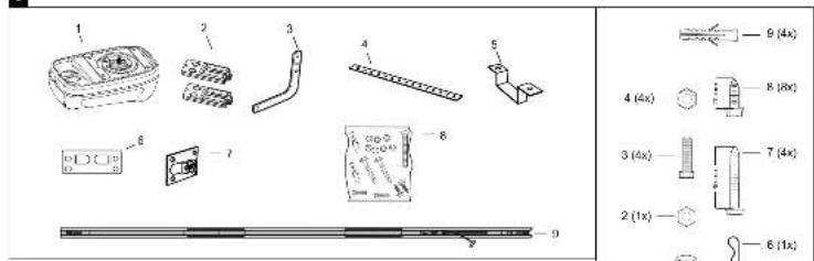
3
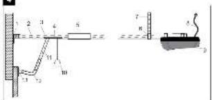
4
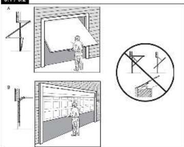
5.1/5.2
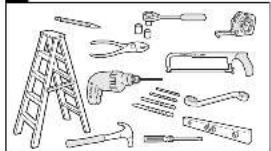
5.3
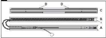
6.1
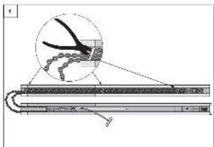
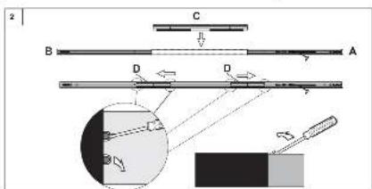
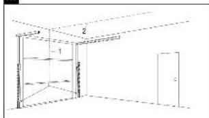
7.1
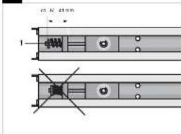
6.2
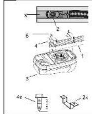
6.3
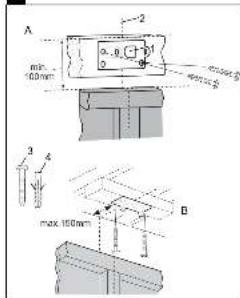
7.2