
B510C - Garage door CHAMBERLAIN - Free user manual and instructions
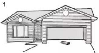
Find the device manual for free B510C CHAMBERLAIN in PDF.
| Product Type | Belt Drive Garage Door Opener |
| Brand | Chamberlain |
| Model | B510C |
| Power Supply | 120 V, 60 Hz |
| Motor Power | Med Lift Power System |
| Drive Type | Belt |
| Compatible Door Height | Up to 2.13 m (7 ft), extension possible |
| Wireless Technology | MyQ® and Security+ 2.0® (900 MHz) |
| Included Remotes | 2 pre-programmed 3-button remotes |
| Wall Control Panel | Multi-function with lock, light, and learn |
| Safety System | Protector System® (infrared reversing sensors) |
| Special Features | Timer-to-close, sleep mode, motion-detecting light |
| Manual Release | Emergency release handle with cord |
| Lighting | Incandescent A19 bulb (100 W max) or compact fluorescent (26 W max) |
| Accessory Memory Capacity | Up to 8 remotes, 2 wall controls, 1 wireless keypad |
| Maintenance | Monthly test of reversing system; lubricate rollers, bearings, and hinges |
| Warranty | Motor 10 years, parts 1 year, accessories 1 year, belt 5 years |
| Approximate Weight | Approximately 13 kg (29 lb) |
| Rail Dimensions | Assembled rail: approximately 2.13 m (7 ft) length |
Frequently Asked Questions - B510C CHAMBERLAIN
User questions about B510C CHAMBERLAIN
0 question about this device. Answer the ones you know or ask your own.
Ask a new question about this device
Download the instructions for your Garage door in PDF format for free! Find your manual B510C - CHAMBERLAIN and take your electronic device back in hand. On this page are published all the documents necessary for the use of your device. B510C by CHAMBERLAIN.
USER MANUAL B510C CHAMBERLAIN
natural_image
Exterior view of a modern office building (no signage)Owner's Manual
B503C • B510C
Belt Drive
Garage Door Opener
TO WATCH VIDEOS GO TO: tinyurl.com/lgh5x3h
CHAMBERLAIN®
Garage Opener
- Please read this manual and the enclosed safety materials carefully!
- Fasten the manual near the garage door after installation.
- The door WILL NOT CLOSE unless the Protector System * is connected and properly aligned.
-
Periodic checks of the garage door opener are required to ensure safe operation.
-
The model number label is located on the left side panel of your garage door opener.
- This garage door opener is compatible with MyQ* and Security+ 2.0* accessories.
- DO NOT install on a one-piece door if using devices or features providing unattended close. Unattended devices and features are to be used ONLY with sectional doors.

Contents
Preparation 2-5
Assembly 6-10
Installation 11-28
Install the Door Control .....21-22
Install the Protector System ^® ....23-26
Connect Power 27
Adjustments....29-31
Operation....32-36
Features 33
Using your Garage Door Opener .....34
Multi-Function Control Panel .....34
Remote Control and Keyless Entry 35 Homelink*
To Erase the Memory ....36
To Open the Door Manually .....37
Maintenance 38
Troubleshooting....39-40
Accessories......41
Warranty....42
Repair Parts 43-44
www.chamberlain.com
www.mychamberlain.com
Preparation
Safety Symbol and Signal Word Review
This garage door opener has been designed and tested to offer safe service pro operated, maintained and tested in strict accordance with the instructions and warning this manual.
WARNING
Mechanical
WARNING
Electrical
CAUTION

WARNING: This product can expose you to chemicals including lead, which State of California to cause cancer or birth defects or other reproductive information go to www.P65Warnings.ca.gov
Unattended Operation
The Timer-to-Close (TTC) feature, ^® SenarMyOne Control app,and ^® Mage Door and Gate Monitor are examples of unattended close and are to be used ONLY with device or feature that allows the door to close without being in the line of sight unattended close. The Timer-to-Close (TTC) feature, ^® SthertMyOne Control, and any other MyQ ^® devicesare to be used ONLY with sectional doors.
Check the Door
ided it is installed.
gs contained in
WARNING
TSignareventpossible SERIOUS INJURY or DEATH:
art • yALWAYS call a trained door systems technician if garage door binds, slicks, or is out of balance. If you App unbalanced garage door may NOT reverse when required.
- NEVER try to loosen, move or adjust garage door,door springs, cables, pulleys, b g their hardware, ALL of which are under EXTREME tension.
- Disable ALL locks and remove ALL ropes connected to garage door BEFORE operating garage door opener to avoid entanglement.
- DO NOT install on a one-piece door if using devices or features providing unattended close.
following attended devices and features are to be used ONLY with sectional doors.
CAUTION
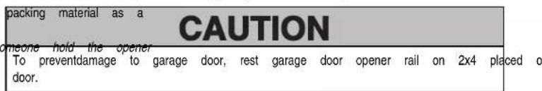
To preventdamage to garage door and opener:
are known to the ALWAYS disable locksBEFORE installing and operating the opener. harm for more ONLY operate garage door opener at 120V,60 Hz to avoid malfu
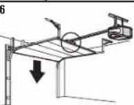
Before you begin:
- Disable locks and remove any ropes connected to the garage door.
- Lift the door halfway up. Release the door. If balanced, it should stay in place, supported entirely by its springs.
- Section doors. Low any the door to check for binding or sticking. If your door of the birds, sticks, or is out of balance, call a trained door system on spring technician.
- Check the seal on the bottom of the door.Anygap between the floor and the bottom of the door must not exceed 1/4 inch (6 mm). Otherwise, the safety reversal system may not work properly.
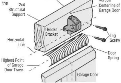
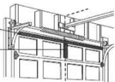
- The opener should be installed above the center of the door. If there is a torsion spring or center bearing plate in the way of the header bracket, it maybe installed within 4 feet (1.2 m) to the left or right of the door center. See page 12.
Preparation
Additional Items You May Need:
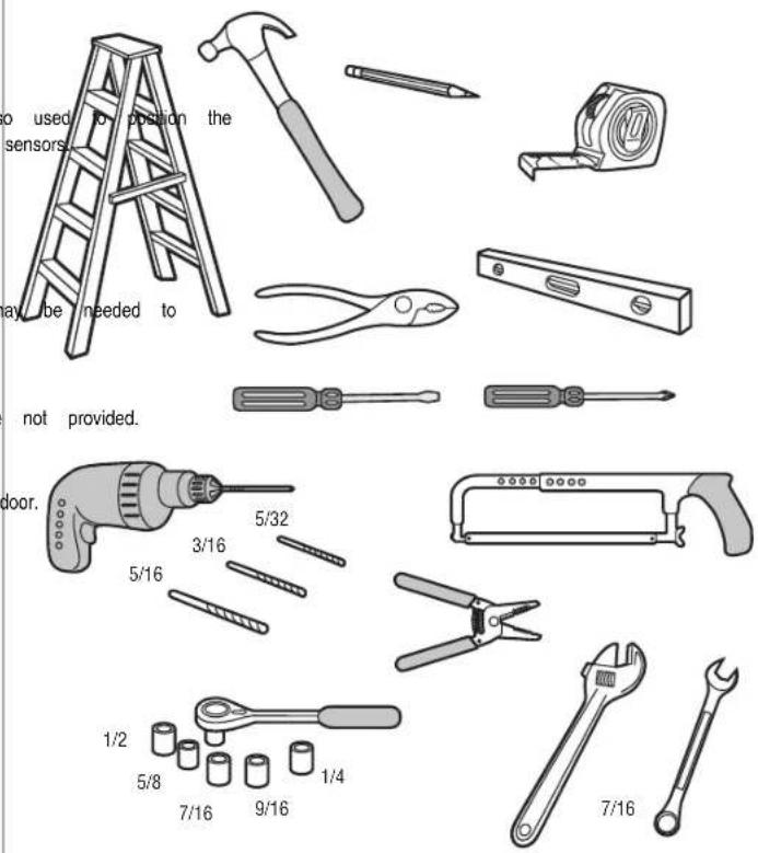
Survey your garage area to see if you will need any of the following items:
■ (2) 2X4 PIECES OF WOOD
Maybe used to fasten the header bracket to the structural supports. A garage door opener during installation and for testing the safetyreversing
■ SUPPORTBRACKET AND FASTENING HARDWARE
Must be used if you have a finished ceiling in your garage.
■ EXTENSION BRACKETS (MODEL 041A5281-1) OR WOOD BLOCKS
Depending upon garage construction, extension brackets or wood blocks may be needed to install the safetyreversing sensor.
■ FASTENING HARDWARE
Alternate floor mounting of the safetyreversing sensor will require hardware
■ DOOR REINFORCEMENT
Required if you have a lightweight steel, aluminum,fiberglassor glasspanel
■ RAIL EXTENSION KIT
Required if your garage door is more than 7 feet (2.13 m) high.
Tools Needed
Preparation
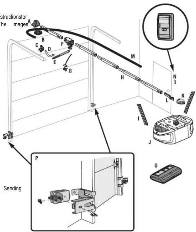
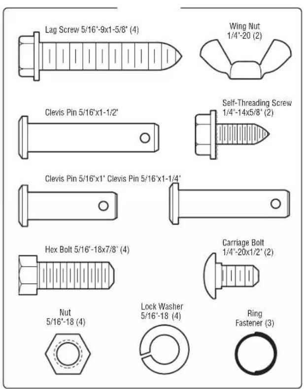
Carton Inventory
Save the carton and packing material until the installation and adjustment is complete. Instructions for
the accessories will be attached to the accessory and are not included in this manual. The images throughout this manual are for reference only and your product may look different.
| Model | Power | DoorControl | Remote | Control | Wireless | Keypad | ||
| B503C | Med | Lift | Power | SystemTM | Multi-Function | 3-button | (2) | |
| B510C | Med | Lift | Power | SystemTM | Multi-Function | 3-button | (2) | √ |
A. Header bracket
B. Pulley
C. Door bracket
D. Curved door arm
E. Straightdoor arm(Packaged inside front rail section)
F. Trolley
NOTE: Be sure to assemble the trolley before sliding onto rail.
G. Emergency release rope and handle
H. Rail (1 front and 4 center sections)
I. Hanging brackets (2) (Packaged inside the front rail section)
J. Garage door opener (motor unit)
K. Sprocketcover and screws
L. "U" bracket
M. Belt
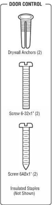
N. Door control
O. Remote control
P. The ProtectorSystem
Safety reversing sensors with 2 conductor white and white/black wire attached: Sending
Sensor (1). Receiving Sensor (1). and SafetySensor Brackets (2)
NOTSHOWN
WirelessKeypad
White and red/white wire
Owner's manual
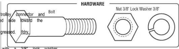
Hardware
Preparation
Hardware
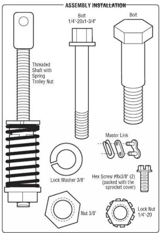
Assembly
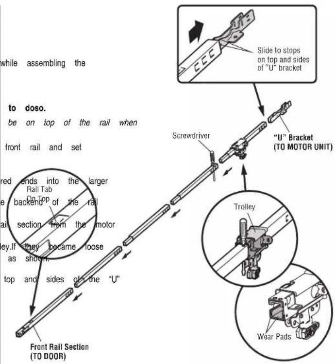
STEP 1 Assemble the rail and install the trolley
CAUTION
To prevent INJURY from pinching, keep hands and fingers away from the joints while assembling the rail.
To avoid installationdifficulties, donot run the garage dooropener until instructed
The front rail has a cut out "window" at the door end. The rail tab MUST assembled.
-
Remove the straight door arm and hanging bracket packaged inside the aside for Installation Step 5 and 9. NOTE: To prevent INJURY while unpacking the rail carefully remove the straight door arm stored within the rail section.
-
Align the rail sections on a flat surface as shown and slide the tapered ends into the larger ones. Tabs along the side will lock into place.
-
Place the motor unit on packing material to protect the cover, and rest the backend of the rail on top. For convenience, put a supportunder the frontend of the rail.
-
As a temporary stop, inserta screwdriver into the hole in the second rail section from the motor unit, as shown.
-
Check to be sure there are 4 plastic wear pads inside the inner trolley. If they became loose during shipping, check all packing material. Snap them back into position as shown.
-
Slide the trolleyassembly toward the screwdriver as shown.
-
Slide the rail onto the "U" bracket, until itreaches all the stops on the top and sides of the "U" bracket.
Assembly
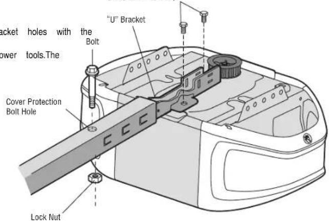
STEP 2 Fasten the rail to the motor unit
CAUTION
To avoid SERIOUS damage to garage door opener, use ONLY those bolts/ta top of the opener.
- Insert a 1/4"-20 x 1-3/4" bolt into the cover protection bolt hole on shown. Tighten securely with a 1/4"-20 locknut. DO NOT overtighten.
- Remove the bolts from the top of the motor unit.
- Use the carton to support the front end of the rail.
- Place the "U" bracket, flat side down onto the motor unit and align the bolt holes.
- Fasten the "U" bracket with the previouslyremoved bolts; DO NOT use any use of power tools may permanently damage the garage door opener.
teners mounted in the
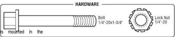
the backend of the rail as Bolts (Mounted in the garage door opener)
Assembly
STEP 3 Install the idler pulley
- Lay the belt beside the rail, asshown.Grasp the end with the hooked tr passapproximately 12" (30 cm) of belt through the window.Keep the ribbed rail,and allow it to hang until AssemblyStep 4.
- Remove the tape from the idler pulley. The inside center should be pre regrease to ensure proper operation.
- Place the idler pulley into the window as shown.
- Insert the idler bolt from the top through the rail and pulley. Tighten and nut underneath the rail until the lock washer is uncompressed.
- Rotate the pulley to be sure itspins freely.
- Locate the rail tab. The rail tab is between the idler bolt and the trolley in the front rail section. Use a flathead screwdriver and lift the rail tab until the tab is vertical (90°).
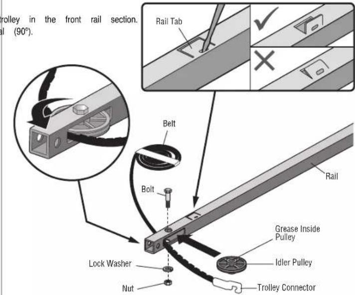
Assembly
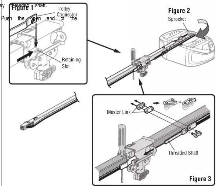
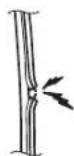
STEP 4 Install the belt
- Pull the belt around the idler pulley and toward the trolley. The ribbed pulley.
- Hook the trolley connector into the retaining slot on the trolley as shown
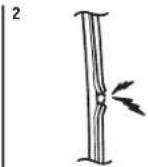
- With the trolley against the screwdriver, dispense the remainder of the belt length toward the motor unit and around the sprocket (Figure 2). The sp engage the belt.
- Check to make sure the belt is nottwisted. Connectthe trolley threaded link (Figure 3).
- Push pins of master link bar through holes in end of belt and trolley
- Push master link cap over pins and past pin notches.
-
Slide the closed end of the clip-on spring over one of the pins. clip-on spring onto the other pin.
-
Remove the spring trolley nut from the threaded shaft.
-
Insert the trolley threaded shaft through the hole in the trolley.
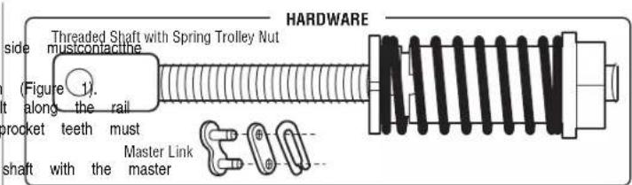
Assembly
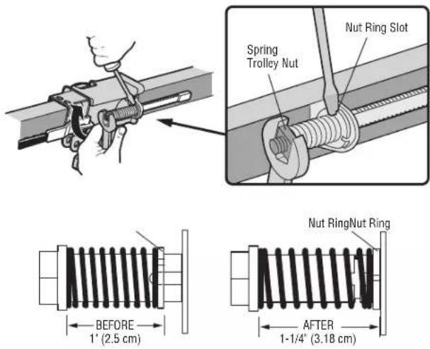
STEP 5 Tighten the belt
- By hand, thread the spring trolley nuton the threaded shaft until it isfin trolley.Do not use any tools.Remove the screwdriver.
- Insert a flathead screwdriver tip into one of the nut ring slots and brace trolley.
- Tighten the spring trolley nut with an adjustable wrench or a 7/16" ope quarter turn until the spring releases and snaps the nutring against the spring to optimum belt tension.
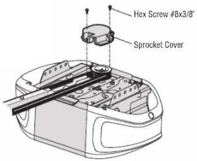
STEP 6 Install the sprocket cover
- Position the sprocket cover over the sprocket as shown and fasten to the 8x3/8" hex screws provided. Youhave now finishedassemblingyour garage door opener.Please read the followingw before proceeding to the installation section.
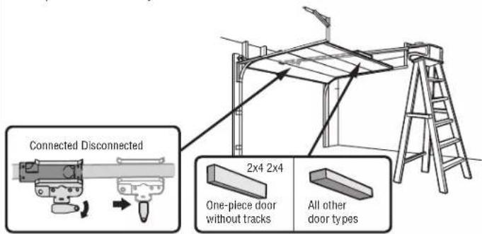
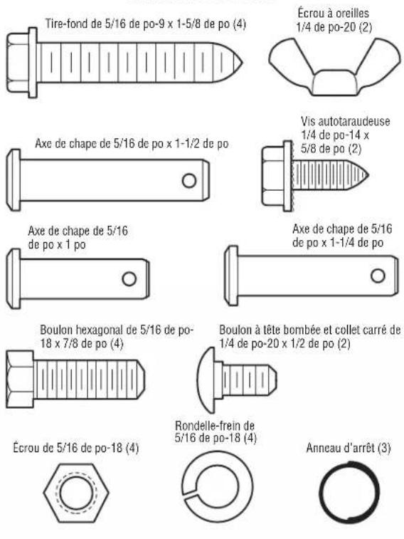
HARDWARE

Hex Screw #8x3/8* (Packed with the sprocket cover)
Installation
IMPORTANT INSTALLATION INSTRUCTIONS
WARNING
To reduce the risk of SEVERE INJURY or DEATH:
- READ AND FOLLOW ALL INSTALLATION WARNINGS AND INSTRUCTIONS. 9. Install wall-mounted garage door control:
- Install garage door opener ONLY on properly balanced and lubricated garage door. within sightofthe garage door.
improperly balanced door may NOT reverse when required and could result in SEVERE of reach of small children at a minimum height of 5 feet (1.5 m) above fl INJURY or DEATH. steps or any other adjacent walking surface. - ALL repairs to cables, spring assemblies and other hardware MUST be made by awayfained Arbor moving partsof the door.
systems technician BEFORE installing opener. 10. Place entrapment warning label on wall next to garage door control. - Disable ALL locks and remove ALL ropes connected to garage door BEFORE Installing an open release/safety reverse test label in plain view on inside of garage] door.
to avoid entanglement. 12. Upon completion of installation, test safety reversal system. Door MUST reverse on cor - Install garage door opener 7 feet (2.13 m) or more above floor. 1-1/2" (3.8 cm) high object (or a 2x4 laid flat) on the floor.
- Mount the emergency release within reach, but at least 6 feet (1.83 m) above 13 the Tlco avoid and SERIOUS PERSONAL INJURY or DEATH from electrocution, disconnect ALL
avoiding contact with vehicles to avoid accidental release. power BEFORE performing ANY service or maintenance. - NEVER connect garage door opener to power source until instructed to do14.so.DO NOT install on a one-piece door ifusing devices or features providing] unatt
- NEVER wear watches, rings or loose clothing while installing or servicing opened unaffected codes and features are to be used ONLY with sectional doors.
be caught in garage door or opener mechanisms.
Installation
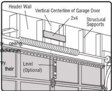
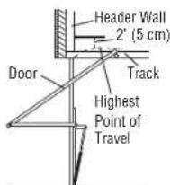
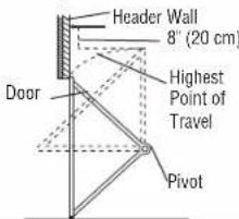
STEP 1 Determine the header bracket location
WARNING
To preventpossible SERIOUS INJURY or DEATH:
- Header bracket MUST be RIGIDLY fastened to structural supporton header wa otherwise garage door might NOT reverse when required.DO NOTinstall header drywall.
• Concrete anchors MUST be used if mounting header bracket or 2x4 into - NEVER try to loosen, move or adjust garage door, springs, cables, pulleys, brack hardware. ALL of which are under EXTREME tension.
- ALWAYS call a trained door systems technician if garage door binds, sticks, or is out of balance. An unbalanced garage door might NOT reverse when required.
Installation procedures vary according to garage door types. Follow the instructions which door.
- Close the door and mark the inside vertical centerline of the garage door.
- Extend the line onto the header wall above the door. You can fasten the 4 feet(1.22 m) of the leftor rightof the door center only if a torsion spring plate is in the way; or you can attach itto the ceiling (see page 13) with (It may be mounted on the wall upside down if necessary, to gain approx you need to install the header bracket on a 2x4 (on wall or ceiling), use provided) to securely fasten the 2x4 to structural supports as shown here and
- Open your door to the highest point of travel as shown. Draw an intersecting the header wall 2" (5 cm) above the high point:
- 2" (5 cm) above the high point for sectional door and one-piece door
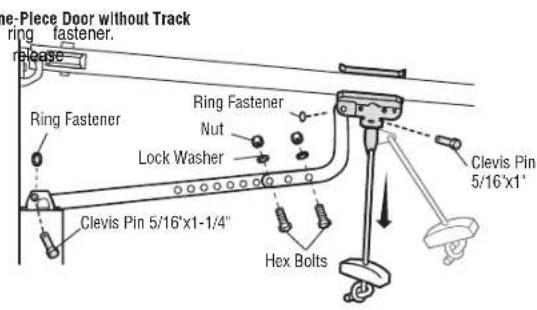
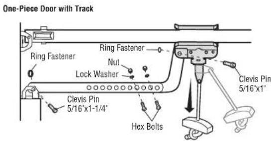
- 8" (20 cm) above the high point for one-piece door without track.
This height will provide travel clearance for the top edge of the door. NOTE: If the total number of inches exceeds the height available in your garage, use the maximum height possible, ceiling installation.
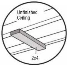
OPTIONAL CEILING MOUNT FOR HEADER BRACKET
which Sectional door with curved track
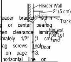
with track. Jamb hardware
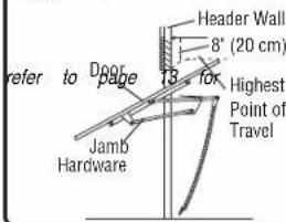
One-piece door with horizontal track
One-piece door without track: pivot hardware
Installation
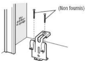
STEP 2 Install the header bracket
You can attach the header bracket either to the wall above the garage door, instructions which will work best for your particular requirements. Do not install the header bracket over drywall. If Installing into masonry, use concrete anchors (not provided).
Lag Screw 5/16"-9x1-5/8"
OPTION A WALL INSTALLATION
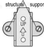
- Center the bracketton the vertical centerline with the bottomedge of the horizontal line as shown (with the arrow pointing toward the ceiling).
- Mark the vertical set of bracket holes.Drill 3/16" pilot holes and fasten structural supportwith the hardware provided.
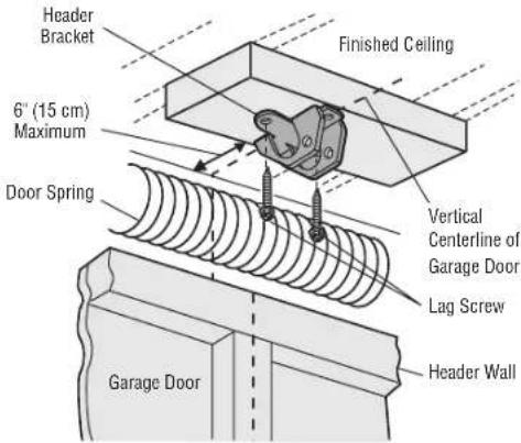
OPTION B CEILING INSTALLATION
- Extend the vertical centerline onto the ceiling as shown.
- Center the bracketon the vertical mark, no more than 6" (15 cm) from arrow is pointing away from the wall. The bracket can be mounted flush when clearance is minimal.
- Mark the side holes.Drill 3/16" pilot holes and fasten bracket securely to with the hardware provided.
WALL INSTALLATION
or to the ceiling.Follow Wall Mounting Holes
Optional Mounting Holes
bracketon the
the bracket securely to a
CEILING INSTALLATION
the wall. Make sure the against the ceiling Holes
Installation
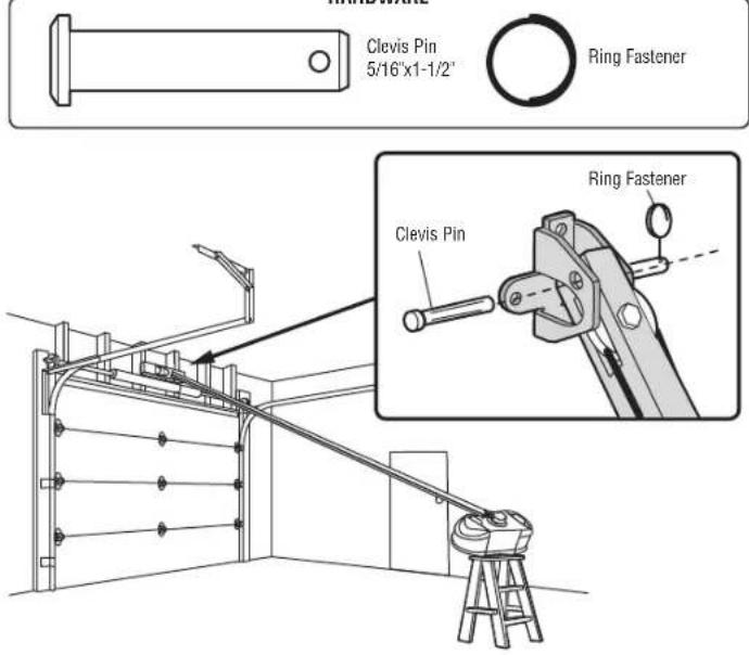
STEP 3 Attach the rail to the header bracket
- Position the opener on the garage floor below the header bracket. Use protective base.
NOTE: If the door spring is in the way, you will need help. Have securely on a temporary support to allow the rail to clear the spring. - Position the rail bracket against the header bracket.
- Align the bracketholes and join with a clevis pin as shown.
- Insert a ring fastener to secure.
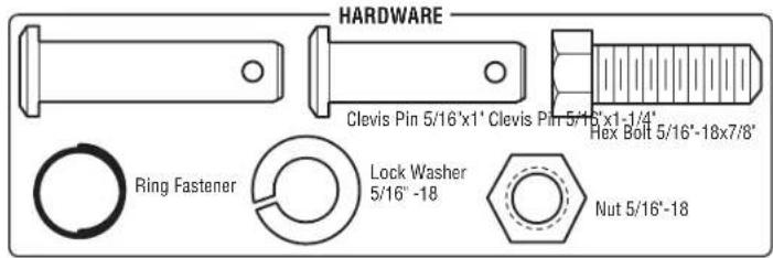
HARDWARE

STEP 4 Position the garage door opener
- Remove the packing material and lifthe garage door opener onto a ladder.
- Fully open the door and place a 2x4 (laid flat) under the rail. For one-piec tracks, lay the 2x4 on it's side.
NOTE: A 2x4 is ideal for setting the distance between the rail and the door. If the ladder is not tall enough you will need help at this point. If the door hits the trolley when it is r release arm down to disconnect the inner and outer trolley. Slide the outer trolley door opener. The trolley can remain disconnected until instructed.
Installation
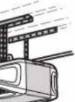
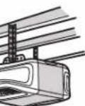
STEP 5 Hang the garage door opener
WARNING
To avoid possible SERIOUS INJURY from a falling garage door opener, faster structural supports of the garage. Concrete anchors MUST be used if installing masonry.
Hanging the garage door opener will vary depending on your garage.Below are installations. Your installation maybe different.For ALL installations the garage door connected to structural supports.The instructions illustrate one of the examples be
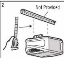
- On finished ceilings, use the lag screwsto attach a support bracket (not structural supports before installing the garage door opener.
- Make sure the garage door opener is aligned with the header bracket. Measure the from each side of the garage door opener to the support bracket.
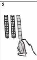
- Cutboth pieces of the hanging bracket to required lengths.
- Attach the end of each hanging bracket to the support bracket with provided).
- Attach the garage door opener to the hanging brackets with the hext nuts.
- Remove the 2x4 and manually close the door. If the door hit the rail,
opEXAMPLES MUST be
low.
provided) to
(1)
asure the d
(1)
m = 311
ts,lockwashers
Fim
raise the n
-
Lag Screw
(1)
(No text)
The Ground Truth image displays a single, solid horizontal line. According to Rule 2 (UNDERSCORE & LINE RULES), this is a stylistic or background line, not a placeholder underscore. Therefore, the OCR result must ignore it and output nothing or only meaningful text. The provided OCR content is "____", which consists of four underscores. This is an incorrect interpretation of the line as a placeholder, violating the rule that stylistic lines must be ignored. The OCR has hallucinated underscores where none should exist based on the GT's visual context. Hence, the OCR result is inconsistent with the Ground Truth.
(No text)
4
(1)
1
m = 311
1
Not
Provided
The Ground Truth image displays a single, solid horizontal line. According to Rule 2 (UNDERSCORE & LINE RULES), this is a stylistic or background line, not a placeholder underscore. Therefore, the OCR result must ignore it and output nothing or only meaningful text. The provided OCR content is "____", which consists of four underscores. This is an incorrect interpretation of the line as a placeholder, violating the rule that stylistic lines must be ignored. The OCR has hallucinated underscores where none should exist based on the GT's visual context. Hence, the OCR result is inconsistent with the Ground Truth.
|
low.
provided) to
1
asure the d
[Non-Text]
(2) 本说明仅供参考。
ppropriate ha
[Non-Text]
ts,lockwashers
Fin
raise the h
-
Lag Screw
1
The Ground Truth image displays a single, solid horizontal line. According to Rule 2 (UNDERSCORE & LINE RULES), this is a stylistic or background line, not a placeholder underscore. Therefore, the OCR result must ignore it and output nothing or only meaningful text. The provided OCR content is "____", which consists of four underscores. This is an incorrect interpretation of the line as a placeholder, violating the rule that stylistic lines must be ignored. The OCR has hallucinated underscores where none should exist based on the GT's visual context. Hence, the OCR result is inconsistent with the Ground Truth.
1
(No text)
4
4
1
m = 311
1
Not
Provided
The Ground Truth image displays a single, solid horizontal line. According to Rule 2 (UNDERSCORE & LINE RULES), this is a stylistic or background line, not a placeholder underscore. Therefore, the OCR result must ignore it and output nothing or only meaningful text. The provided OCR content is "____", which consists of four underscores. This is an incorrect interpretation of the line as a placeholder, violating the rule that stylistic lines must be ignored. The OCR has hallucinated underscores where none should exist based on the GT's visual context. Hence, the OCR result is inconsistent with the Ground Truth.
|
provided) to
1
asure the d
[Non-Text]
ppropriate ha
[Non-Text]
ts,lockwashers
HH
raise the h
-
Lag Screw
1
-
1
(No text)
4
4
ppropriate ha
(1)
ts,lockwashers Fin
rise the h
raise the n
三
Lag Screw
1
The Ground Truth image displays a single, solid horizontal line. According to Rule 2 (UNDERSCORE & LINE RULES), this is a stylistic or background line, not a placeholder underscore. Therefore, the OCR result must ignore it and output nothing or only meaningful text. The provided OCR content is "____", which consists of four underscores. This is an incorrect interpretation of the line as a placeholder, violating the rule that stylistic lines must be ignored. The OCR has hallucinated underscores where none should exist based on the GT's visual context. Hence, the OCR result is inconsistent with the Ground Truth.
(No text)
4
4
1
1
Not
Provided
[Non-Text]
|
5
m = 311
[Non-Text]
[Non-Text]
[Non-Text]
[Non-Text]
[Non-Text]
[Non-Text]
[Non-Text]
[Non-Text]
[Non-Text]
[Non-Text]
[Non-Text]
[Non-Text]
[Non-Text]
[Non-Text]
[Non-Text]
[Non-Text]
[Non-Text]
[Non-Text]
[Non-Text]
[Non-Text]
[Non-Text]
[Non-Text]
[Non-Text]
[Non-Text]
[Non-Text]
[Non-Text]
[Non-Text]
[Non-Text]
[Non-Text]
[Non-Text]
[Non-Text]


Unfinished Ceiling
Installation
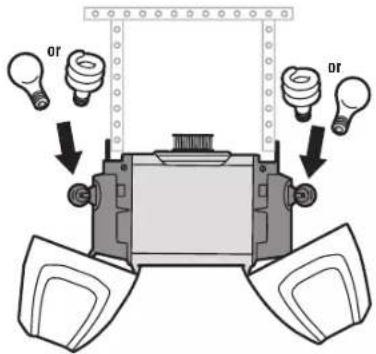
STEP 6 Install the light bulbs
CAUTION
To prevent possible OVERHEATING of the end panel or light socket:
-
Use ONLY A19 incandescent(100W maximum) or compact fluorescent(26W max bulbs.
• DO NOT use incandescent bulbs larger than 100W.
• DO NOT use compact fluorescentlight bulbs larger than 26W (100W equivalent)
• DO NOT use halogen bulbs.
• DO NOT use short neckor specialty lightbulbs. -
Pull on the top sides of the light lens and rotate the light lensdown.
- Insertan A19 incandescent (100W maximum) or compactfluorescent(26W,100W equivalent) light bulb into the light socket.
- Rotate the lens up to close.
NOTE: Do not use halogen, short neck, or specialty light bulbs as these may overheat the end panel or light socket. Do not use LED bulbs as they may reduce the range or pe controls.
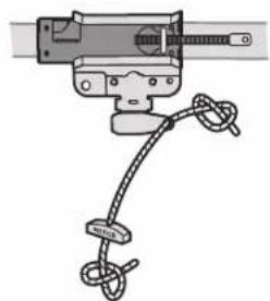
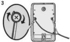
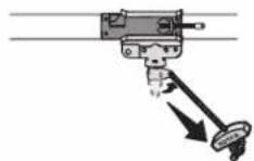
STEP 7 Attach the emergency release rope and handle
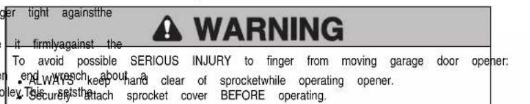
WARNING
To prevent possible SERIOUS INJURY or DEATH from a falling garage door: (m) If light possible, use emergency release handle to disengage trolley ONLY when garage CLOSED. Weak or broken springs or unbalanced door could result in an open rapidly and/or unexpectedly.
- NEVER use emergency release handle unlessgarage doorway is clear of persona obstructions.
-
NEVER use handle to pull door open or closed. If rope knot becomes untied,
-
Insertone end of the emergency release rope through the handle. Make sure is rightside up. Secure with an overhand knot at least1" (2.5 cm) from the preventslipping.
-
Insert the other end of the emergency release rope through the hole in the t Mount the emergency release within reach, but at least 6 feet (1.83 m) above floe contact with vehicles to prevent accidental release and secure with an overhand
NOTE: If it is necessary to cut the emergency release rope, seal the cut end with a match or lighter to prevent unraveling. Ensure the emergency release rope and handle are above the to avoid entanglement.
natural_image
Diagram of a mechanical clamp or spring device with rope and clasp (no text or symbols)Installation
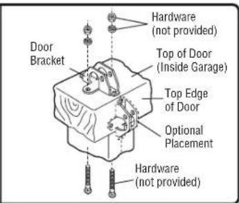
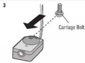
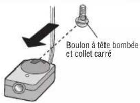
STEP 8 Install the door bracket
CAUTION
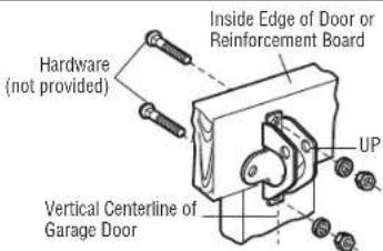
Fiberglass, aluminum or lightweight steel garage doors WILL REQUIRE reinforcement BEFORE installation of door bracket. Contact the garage door manufacturer or installing dealer reinforcement instructions or reinforcement kit. Failure to reinforce the top section according to the door manufacturer may void the door warranty.
A horizontal and vertical reinforcement is needed for lightweight garage doors (f steel, doors with glass panel,etc.) (notprovided). A horizontal reinforcement brace enough to be secured to two or three vertical supports.A vertical reinforcement height of the top panel. Contact the garage door manufacturer or installing dealer reinforcement instructions or reinforcementkit.
NOTE: Many door reinforcement kits provide for direct attachment of the clevis pin and door arm. In this case you will not need the door bracket; proceed to the next step.
OPTION A SECTIONAL DOORS
- Center the door bracket on the previously marked vertical centerline used bracket installation. Note correct UP placement, as stamped inside the bracket.
- Position the top edge of the bracket 2"-4" (5-10 cm) below the top edge directly below any structural support across the top of the door.
- Mark, drill holes and install as follows, depending on your door's construction.
Metal orlight weight doors usinga verticalangle iron brace between the door the door bracket:
- Drill 3/16" fastening holes. Secure the door bracket using the two 1/4"-14x5/8" self-threading screws. (Figure 1)
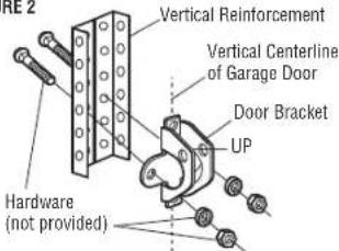
• Alternately, use two 5/16"-18x2" bolts, lock washers and nuts (not provided). (Figure 2)
Metal, insulated orlight weight factory reinforced doors:
- Drill 3/16" fastening holes. Secure the door bracket using the self-threading screws. (Figure 3)
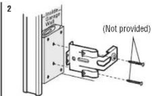
Wood doors:
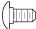
- Use top and bottom or side to side door bracket holes. Drill 5/16" holes through the door and secure bracket with 5/16"-18x2" carriage bolts, lockwashers and nuts (not provided). (Figure 4)
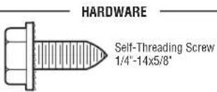
NOTE: The 1/4"-14x5/8" self-threading screws are not intended for use on wood doors.
Self-Threading Screw 1/4"-14x5/8"
for opener as required
Horizontal Reinforcement
berglass, aluminum.
should be long Vertical Reinforcement brace should cover the for opener
FIGURE 1
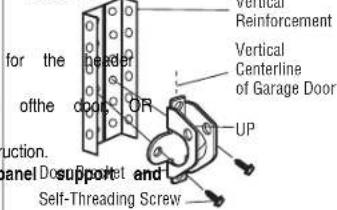
FIGURE 3 FIGURE
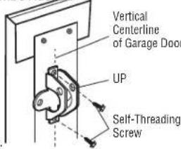
FIGURE 2
Installation
STEP 8 Install the door bracket (continued)
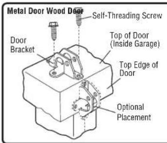
OPTION B ONE-PIECE DOORS
- Center the door bracket on the top of the door, in line with the header
- Mark either the left and right, or the top and bottom holes.
Metal Doors:
- Drill 3/16" pilot holes and fasten the bracket with the self-threading screws provided.
Wood Doors:
- Drill 5/16" holes and use 5/16"-18x2" carriage bolts, lock washers and nuts (not provided) or 5/16"x1-1/2" lag screws (not provided) depending on your installation needs.
NOTE: The door bracket may be installed on the top edge of the door if required for your installation. (Refer to the dotted line optional placement drawing.)
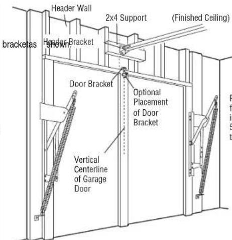
For a door with no exposed framing, or for the optional installation, use lag screws 5/16"x1-1/2" (not provided) to fasten the door bracket.
Installation
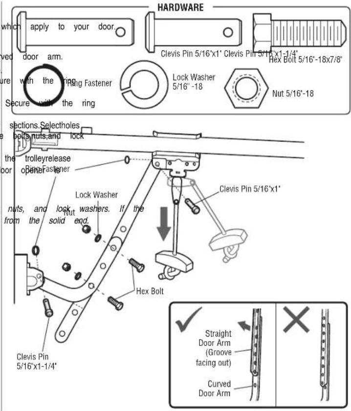
STEP 9 Connect the door arm to the trolley
Installation will vary according to the garage door type. Follow the instructions
OPTION A SECTIONAL DOORS
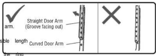
IMPORTANT: The groove on the straightdoor arm MUST face away from the curved
- Close the door. Disconnect the trolley by pulling the emergency release handle.
- Attach the straightdoor arm to the outer trolley using the clevispin. Secure fastener.
- Attach the curved door arm to the door bracket using the clevis pin. fastener.
- Bring arm sections together. Find two pairsof holes thatline up and join as far apartas possible to increase door arm rigidity and attach using the washers.
- Pull the emergency release handle toward the garage door opener until the arm is horizontal. The trolleywill re-engage automatically when the garage door activated.
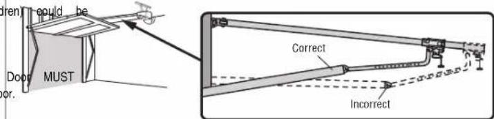
NOTE: If the holes in the curved door arm and the straight door arm do not align, reverse the straight door arm, select two holes (as far apart as possible) and attach using bolts, straight door arm is hanging down too far, you may cut 6 inches (15 cm)
Installation
STEP 9 Connect the door arm to the trolley (continued) OPTION B ONE-PIECE DOORS
IMPORTANT: The groove on the straight door arm MUST face away from the curved door
- Close the door. Disconnect the trolley by pulling the emergency release h
- Fasten the straight door arm and the curved door arm together to the (with a 2 or 3 hole overlap) using the bolts, nuts, and lockwashers.
- Attach the straight door arm to the door bracket using the clevispin. \$ fastener.
- Attach the curved door arm to the trolley using the clevis pin. Secure
- Pull the emergency release handle toward the garage door opener until arm is horizontal.
Installation
STEP 10 Install the door control


WARNING
To prevent possible SERIOUS INJURY or DEATH from electrocution:
- Be sure power is NOT connected BEFORE installing door control.
- Connectdoor control ONLY to 12 VOLT low voltage wires.
To prevent possible SERIOUS INJURY or DEATH from a closing garage door:
• Install door control within sight of garage door, out of reach of small children at a minimum
height of 5 feet (1.5 m) above floors, landings, steps or any other adjacent away from ALL moving parts of door.
- NEVER permit children to operate or play with door control push buttons transmitters.
- Activate door ONLY when it can be seen clearly, is properly adjusted, obstructions to door travel.
- ALWAYS keep garage door in sight until completely closed. NEVER permit an path of closing garage door.
INTRODUCTION
Compatible with MyCabled accessories, see page 41. Your garage door opener up to 2 ^® MyC controls. NOTE: Older Chamberlain door controls and third party products are not compatible.
Install the door control within sight of the door at a minimum height of 5 feet landings, steps or any other adjacent walking surface, where small children cannot from the moving parts of the door. For gang box installations it is not necessary drywall anchors. Use the existing holes in the gang box.
NOTE: Your product may look different than the illustrations.
HARDWARE
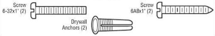
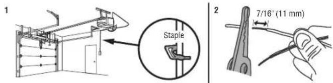
- Strip 7/16 inch (11 mm) of insulation from one end of the wire and separa
- Connect one wire to each of the two screws on the back of the door coil connected to either screw. If your garage is pre-wired for the door control cl wires to connect, note which wires are used so the correct wires are connected door opener in a later step.
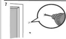
- Mark the location of the bottom mounting hole and drill a 5/32 inch hole.
- Install the bottom screw, allowing 1/8 inch (3 mm) to protrude from the wall.
- Position the bottom hole of the door control over the screw and slide dow
- Lift the push bar up and mark the top hole.
- Remove the door control from the wall and drill a 5/32 inch hole for the surface and position the bottom hole of the door control over the screw and slide dow
or remote top control screw.
|2 3

is compatible with
natural_image
Simple line drawing of a door with a magnified inset showing a screwdriver tip (no text or symbols)18
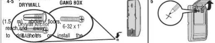
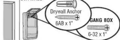
DRYWALL
Installation
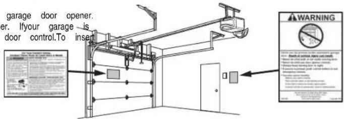
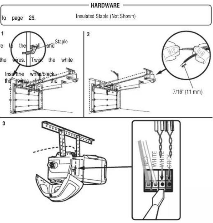
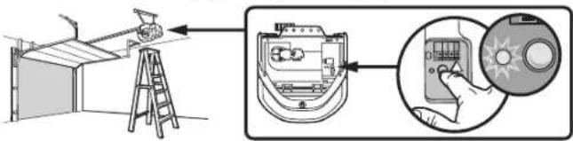
STEP 11 Wire the door control to the garage door oSTEP 12 Attach the warning labels
- Run the white and red/white wire from the door control to the garage door1. oathn Attachentrapmentwarning label on the wall near the door control with t wire to the wall and ceiling with the staple (not applicable for gang box 2. attached the manual release/safetyreverse test label in a visible location on the installations). Do not pierce the wire with the staple as this may cause a short or garage-pedoor.
- Strip 7/16 inch (11 mm) of insulation from the end of the wire near the garage door opener.
- Connect the wire to the red and white terminals on the garage door opener. If your garage is pre-wired make sure you use the same wires that are connected to the door control. To insert or release wires from the terminal, push in the tab with screwdriver tip.
HARDWARE
Insulated Staple (Not Shown)
3
Installation
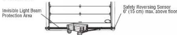
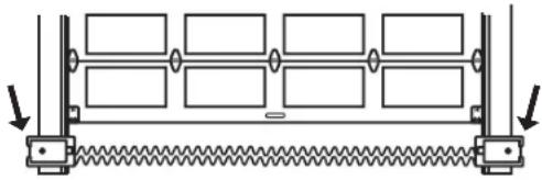
STEP 13 Install the Protector® System
WARNING
Be sure power is NOT connected to the garage door opener BEFORE ins sensor.
To prevent SERIOUS INJURY or DEATH from closing garage door:
- Correctly connect and align the safety reversing sensor. This required safety device MUST NOT be disabled.
• Install the safety reversing sensor so beam is NO HIGHER than 6" (15 cm) above garage floor.
IMPORTANT INFORMATION ABOUT THE SAFETY REVERSING SENSORS
The safety reversingsensors must be connected and aligned correctly before openerwillmove in the down direction.
The sending sensor (with an amber LED) transmits an invisible light beam to a green LED). If an obstruction breaks the lightbeam while the door is closing, the reverse to the full open position, and the garage door opener lights will flash. NOTE: For energy efficiency the garage door opener will enter sleep mode when closed. The sleep mode shuts the garage door opener down until activated. The sequenced with the garage door opener light bulb; as the light bulb turns off, off and whenever the garage door opener lights turn on the sensor LEDs will open will not go into the sleep mode until the garage door opener has co-power up.
When installing the safety reversing sensors check the following:
- Sensors are installed inside the garage, one on either side of the door.
- Sensors are facing each other with the lenses aligned and the receiving sensor lens does not receive direct sunlight.
- Sensors are no more than 6 inches (15 cm) above the floor and the unobstructed.
Facing the door from inside the garage
ling the safetyreversing
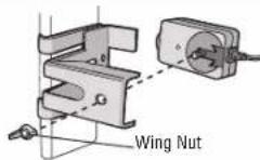
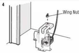
HARDWARE
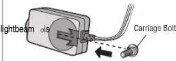
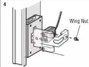
Carriage Bolt 1/4"-20 x 1/2"
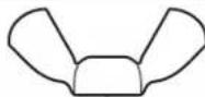
Wing Nut 1/4'-20
The safetyreversing sensors can be attached to the door track,the wall, or the floor be no more than 6 inches (15 cm) above the floor. Ifthe door track will not s wall installation is recommended. Choose one ofthe following installations.
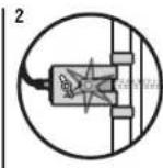
OPTION A DOOR TRACK INSTALLATION
-
Slide the curved arms of the sensor bracket around the edge of the door trap place so that the sensor bracket is flush against the track.
-
Slide the carriage bolt into the sloton each sensor.
-
Insert the bolt through the hole in the sensor bracket and attach with the win
on both sensor should pointtoward each other. Make sure the lensis not obsl
receiving sensor floor will stop and
101 times.
when the door is fully The sleep mode is off the sensor LEDs will light. The garage door completed 5 cycles upon
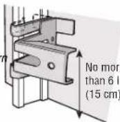
No more than 6 inches (15 cm)
2
3
Installation
STEP 13 Install the Protector® (Systemed)
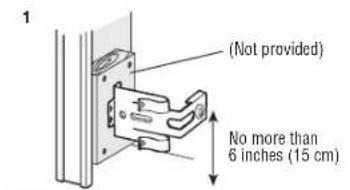
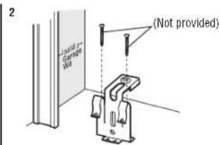
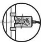
OPTION B WALL INSTALLATION
If additional clearance is needed an extension bracket (not provided) or wood Make sure each bracket has the same amountofclearance so they will align
- Position the sensor bracket against the wall with the curved armsfacing there isenough clearance for the beam to be unobstructed. Markholes.
- Drill 3/16 inch pilot holes for each sensor bracket and attach the ser using lag screws (notprovided).
- Slide the carriage bolt into the slot on each sensor.
- Insert the boltthrough the hole in the sensor bracket and attach with on both sensors should point toward each other. Make sure the lens sensor bracket.
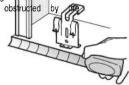
OPTION C FLOOR INSTALLATION
Use an extension bracket (not provided) or wood blockto raise the sensor bracket
- Carefully measure the position of both sensor bracketsso they will be the s blocks can be used by the wall and unobstructed.
correctly2. Attach the sensor bracketsto the floor using concrete anchors (notprovided). the Door Slide make the carriage bolt into the slot on each sensor. - Insert the bolithrough the hole in the sensor bracket and attach with the sensor brackets both sensors should point toward each other. Make sure the lens is no sensor bracket.
e wing put.The lenses
not obstructed by th
Installation
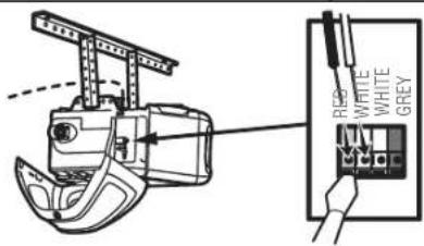
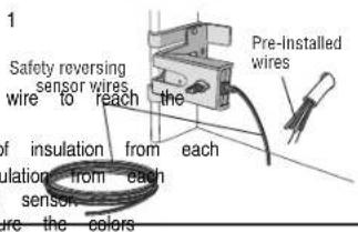
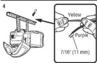
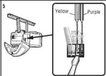
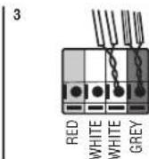
STEP 14 Wire the Safety Reversing Sensors
If your garage already has wires installed for the safety reversing sensors, proceed
OPTION A INSTALLATION WITHOUT PRE-WIRING
- Run the wire from both sensorsto the garage door opener. Attach the wire ceiling with the staples.
- Strip 7/16 inch (11 mm) of insulation from each set of wires. Separate the wires together. Twist the white/black wires together.
- Insert the white wires into the white terminal on the garage door opener, wires into the greyterminal on the garage door opener. To insert or remove terminal, push in the tab with a screwdriver tip.
Installation
STEP 14 Wire the Safety Reversing Sensors (continued) OPTION B PRE-WIRED INSTALLATION
- Cutthe end of the safetyreversing sensor wire, making sure there is enough pre-installed wires from the wall.
- Separate the safety reversing sensor wires and strip 7/16 inch (11 mm) end. Choose two of the pre-installed wires and strip 7/16 inch (11 mm) of end. Make sure that you choose the same color pre-installed wires for each
- Connect the pre-installed wires to the sensor wires with wire nuts making correspond for each sensor. For example, the white wire would connect the white/blackwire would connect to the purple wire.
- At the garage door opener, strip 7/16 inch (11 mm) of insulation from previously chosen for the safety reversing sensors. Twistthe like-colored wire
- Insert the wires connected to the white safetysensor wires to the white door opener. Insertthe wires that are connected to the white/blacksafety se greyterminal on the garage door opener.
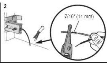
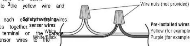
To insert or remove the wires from the terminal, push in the tab with a screwdriver tip.
Installation
STEP 15 Connect power
WARNING
To prevent possible SERIOUS INJURY or DEATH from electrocution or fire:
- Be sure power is NOT connected to the opener, and disconnectpower to removing cover to establish permanent wiring connection.
- Garage door installation and wiring MUSTbe in compliance with ALL local building codes.
- NEVER use an extension cord, 2-wire adapter, or change plug in ANY way to make it fit outlet. Be sure the opener is grounded.
To avoid installationdifficulties, donot runthe openerat this time.
To reduce the risk of electric shock, your garage door opener has a grounding grounding pin. This plug will only fit into a grounding type outlet. If the plug do have, contact a qualified electrician to install the proper outlet.
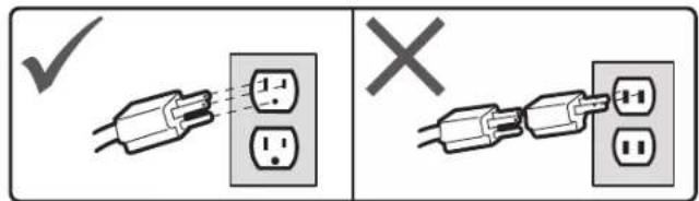
THERE ARE TWO OPTIONS FOR CONNECTING POWER:
OPTION A TYPICAL WIRING
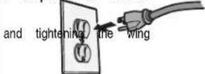
- Plug in the garage door opener into a grounded outlet.
- DO NOT run garage door opener at this time.
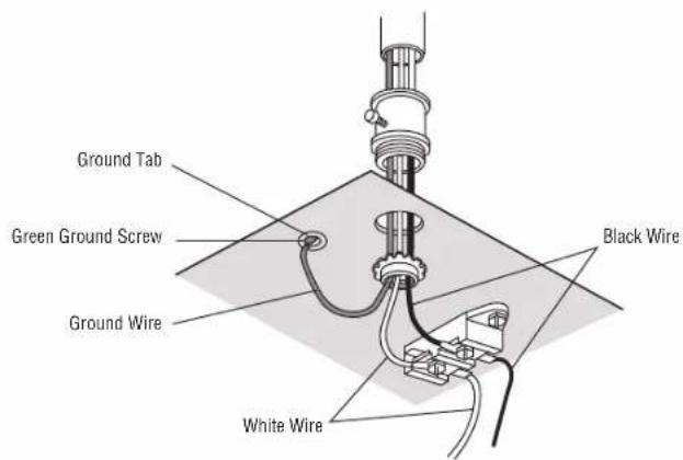
OPTION B PERMANENT WIRING
If permanent wiring is required by yourlocal code, refer to the following procedure. 1 electrical and permanent connection through the 7/8 inch hole in the top of the motor unit (code):
- Remove the motor unit cover screws and set the cover aside.
- Remove the attached 3-prong cord.
- Connect the black(line) wire to the screw on the brass terminal; the white
type plug screw on the silver terminal; and the ground wire to the green ground scr isn't fit in must be grounded.
- Reinstall the cover.
Installation
STEP 16 Aligning the safety reversing sensors
The door will not close if the sensors have not been installed and aligned
When the lightbeam is obstructed or misaligned while the door is closing, the garage door opener lightswill flash ten times. If the door isalreadyopen, it will
- Check to make sure the LEDs in both sensors are glowing steadily. will glow steadily if they are aligned and wired correctly.
The sensors can be aligned by loosening the wing nuts, aligning the sensors, nuts.
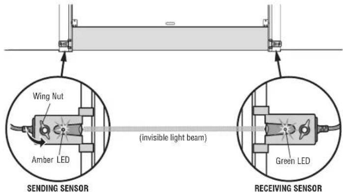
If the receiving sensor is in direct sunlight, switch it with sending sensor so it is on the opposite side of the door.
IF THE AMBER LED ON THE SENDING SENSOR IS NOT GLOWING:
- Make sure there is power to the garage door opener.
- Make sure the sensor wire is not shorted/broken. or will make sure and the sensor has been wired correctly:white wires to white terminal t close. wires to grey terminal.
The LEDsin both sensors
IF THE GREEN LED ON THE RECEIVING SENSOR IS NOT GLOWING:
- Make sure the sensor wire is not shorted/broken.
- Make sure the sensors are aligned.
1
STEP 17 Ensure the door control is wired correctly
If the door control has been installed and wired correctly, the command LED on the Control Panel will blink.
Adjustments
Introduction
WARNING
Without a properly installed safety reversal system, persons (particularly small child SERIOUSLY INJURED or KILLED by a closing garage door.
- Incorrect adjustment of garage door travel limits will interfere with proper operation of safety reversal system.
- After ANY adjustments are made, the safety reversal system MUST be tested. reverse on contact with 1-1/2" (3.8 cm) high object(or 2x4 laid flat) on
CAUTION
To prevent damage to vehicles, be sure fully open door provides adequate clea
Your garage door opener is designed with electronic controls to make setup and adjustments allow you to program where the door will stop in the open (UP) position. The electronic controls sense the amount of force required to open an force is adjusted automatically when you program the travel.
NOTE: If anything interferes with the door's upward travel it will stop. If anything interferes with the door's downward travel, it will reverse.
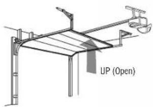
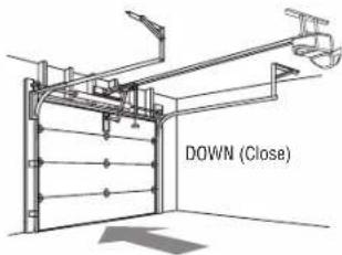
One-Piece Doors Only
When setting the UP travel for a one-piece door ensure that the door does not slant fully open (UP). If the door is slanted backward this will cause unnecessary bucking when the door is opening or closing.
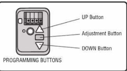
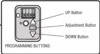
Programming Buttons
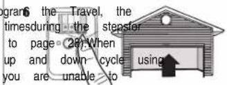
The programming buttons are located on the left side panel of the garage door open program the travel. While programming, the UP and DOWN buttons can be used to
needed adjustments easy. The and (DOWN)
Adjustments
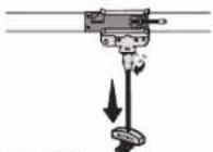
STEP 1 Program the Travel
WARNING
Without a properly installed safety reversal system, persons (particularly small children SERIOUSLY INJURED or KILLED by a closing garage door.
- Incorrect adjustment of garage door travel limits will interfere with proper operation of safety reversal system.
- After ANY adjustments are made, the safety reversal system MUST be tested. reverse on contact with 1-1/2" (3.8 cm) high object(or 2x4 laid flat) on
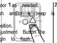
While programming, the UP and DOWN buttons can be used to move the door 1 as needed.
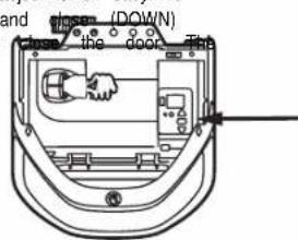
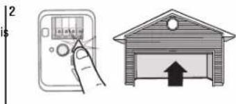
- Pressand hold the Adjustment Button until the UP Button begins to flas heard.
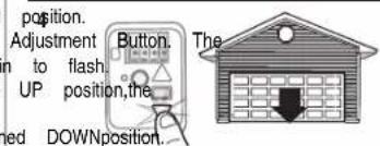
- Pressand hold the UP Button until the door is in the desired UP po
- Once the door is in the desired UP position press and release the Ad garage door opener lights will flash twice and the DOWNButton will be IMPORTANT NOTE: For one-piece door installations refer to page 29.
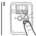
- Pressand hold the DOWNbutton until the door is in the desired DOWN
- Once the door is in the desired DOWN position press and release the garage door opener lights will flash twice and the UP Button will begin
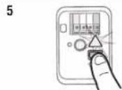
- Pressand release the UP Button.When the door travelsto the programmed DOWN Button will begin to flash.
- Press and release the DOWN Button. The door will travel to the program Programming is complete.
* If the garage door opener lights are flashing 5 times during the steps for Programming has timed out. If the garage door opener lights are flashing 10 Program the Travel, the safety reversing sensors are misaligned or obstructed (refer the sensors are aligned and unobstructed, cycle the door through a complete the remote control or the UP and DOWN buttons. Programming is complete. If operate the door up and down, repeat the steps for Programming the Travel.
natural_image
Illustration of a hand holding an electrical control panel next to a brick house with a downward arrow (no text or symbols)
To watch a video, go to tinyurl.com/lkwbnhj
Adjustments
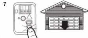
STEP 2 Test the Safety Reversal System
WARNING
Without a properly installed safety reversal system, persons (particularly small child SERIOUSLY INJURED or KILLED by a closing garage door.
- Safety reversal system MUST be tested every month.
-
After ANY adjustments are made, the safety reversal system MUST be tested. reverse on contact with 1-1/2" (3.8 cm) high object (or 2x4 laid flat) on t
-
With the door fully open, place a 1-1/2 inch (3.8 cm) board (or a centered under the garage door.
- Pressthe remote control push button to close the door. The door MUST makes contact with the board.
If the door stops and does not reverse on the obstruction, increase the down travel Step 1). Repeat the test. When the door reverses upon contact with the 1-1/2 inch board and open/close the door 3 or 4 times to test the adjustment. If the ga to fail the safety reversal test, call a trained door systems technician.
natural_image
Hand-drawn sketch of a two-story house with a garage and windows (no text or symbols)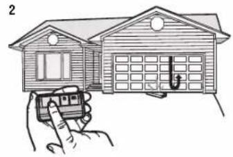
natural_image
Illustration of a house being held by hand, showing front and rear views (no text or symbols)STEP 3 Test the Protector® System
WARNING
Without a properly installed safetyreversing sensor, persons (particularly small children) SERIOUSLY INJURED or KILLED by a closing garage door.
Door 1 MUST Open the door. Place the garage door opener carton in the path of the do floor. Press the remote control push button to close the door. The door will not move inch (2.5 cm), and the garage door opener lights will flash 10 times.
2x4 The laid flat) on the floor, will not close from a remote control if the LEDin either s is off (alerting door to the fact that the sensor is misaligned or obstructed). If the ga reverse when it closes the door when the safety reversing sensor is obstructed (and the sensors are 6 inches [15 cm] above the floor), call for a trained door systemstechnician.
(refer to Adjustment
board, remove the arage door opener continues
natural_image
Line drawing of a two-story house with a garage and parked space (no text or symbols)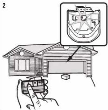
Operation
IMPORTANT SAFETY INSTRUCTIONS
WARNING
To reduce the risk of SEVERE INJURY or DEATH:
- READ AND FOLLOW ALL WARNINGS AND INSTRUCTIONS.
- ALWAYS keep remote controls out of reach of children. NEVER permit children to Safe pre-versor system MUST be tested every month. Garage door MUST revers play with garage door control push buttons or remote controls. with 1-1/2' (3.8 cm) high object(or a 2x4 laid flat) on the floor. Failure to
- ONLY activate garage door when it can be seen clearly, it is properly adjusted, and otherwise properly increases the risk of SEVERE INJURY or DEATH.
obstructions to door travel. - ALWAYS KEEP GARAGE DOOR PROPERLY BALANCED (see page 2). An in
- ALWAYS keep garage door in sight and away from people and objects until completely closed door may NOT reverse when required and could result in SEVERE NO ONE SHOULD CROSS THE PATHOF THE MOVING DOOR. DEATH.
- NO ONE SHOULD GO UNDER A STOPPED, PARTIALLY OPENED DOOR. 12. ALL repairs to cables, spring assemblies and other hardware, ALL of which an
- If possible, use emergency release handle to disengage trolley ONLY when garage EXTREME tension, MUSTbe made by a trained door systems technician. CLOSED. Use caution when using this release with the door open. Weak or 3.broKAWAYingsconnect electric power to garage door opener BEFORE making AM unbalanced door could result in an open door falling rapidly and/or unexpectedly and embossingovers.
the riskof SEVERE INJURY or DEATH. 14. This operator system is equipped with an unattended operation feature. The c - NEVER use emergency release handle unless garage doorways clear of persons and unexpectedly. NO ONE SHOULD CROSS THE PATHOF THE MOVING DOOR. 15. DO NOT install on a one-piece door if using devices or features providing obstructions.
- NEVER use handle to pull garage door open or closed. Ifrope knot becomes untied, that yended out devices and features are to be used ONLY with sectional doors.
16. SAVE THESE INSTRUCTIONS.
Operation
Features
Your garage door opener is equipped with features to provide you with greater garage door operation.
MyQ®
MyQ® technology uses a 900MHz signal to provide two-way communication between opener and MyCabled accessories. Your garage door opener is compatible with accessories. For Smartphone App control of your garage door open-accessor, either Chamberlain's MyCInternet Gateway (model CIGBUC) is required.
TIMER-TO-CLOSE (DO NOT enable on one-piece doors)
The Timer-to-Close feature is not available on all door controls. Below is a list Timer-to-Close feature:
041A7305-1 SmartControl Panel and 041A7327-1 Motion Detecting Control Panel The Timer-to-Close feature automatically closes the garage door after a specified time period. DO NOT
enable TTC if operating a one-piece door. TTC is tobe used ONLY with default is set to off. The garage door opener will beep and the lightswill
The TTC feature will deactivate if the garage door encounters an obstruction to reversing sensors are incorrectly installed. The garage door will reverse open and until the obstructions are clear or the safetyreversing sensors are correctly installed. Obstruction has been cleared or the safetyreversing sensors have been aligned, when the garage door opener isactivated. TTC WILL NOT workif the garage door by battery power or ifthe safety reversing sensors are misaligned. Thisfeature is the primary method of closing the door. A keyless entry should be installed accidentallock out when using this feature.
REMOTE CONTROLS AND DOOR CONTROLS® (MyQ
Your garage door opener has already been programmed at the factory to op control, which changes with each use, randomly accessing over 100 billion new MyQ® enabled accessories, see page 41.
NOTE: Older Chamberlain remote controls, door controls, and third party products are not compatible.
| MyQ®Accessories | MEMORY CAPACITY | |||
| Remote Controls Up to 8 | ||||
| Door Controls | Up to 2®dMyQ controls | |||
| KeylessEntries Up to 1 | ||||
THE PROTECTOR SYSTEM SAFETY REVERSING SENSORS)
When properly connected and aligned, the safety reversing sensors will detect an ot path of the infrared beam. If an obstruction breaks the infrared beam while the door the will garage and/or reverse to full open position, and the opener lightswill flash 10 time up to and MyQ remote control. However, you can close the door if you hold the button on the door entry until the door is fully closed. The safety reversing sensors do not effect the open
ENERGY CONSERVATION
For energy efficiency the garage door opener will enter sleep mode when the door sleep mode shuts the garage door opener down until activated. The sleep mode is garage door opener light bulb; as the light bulb turns off the sensor LEDswill turn garage door opener lightsturn on the sensor LEDswill light.The garage door opener's sectional operator factory till the garage door opener has completed 5 cyclesupon power to switch closing the door.
Service or the safety The garage door opener light bulbs will turn on when the opener is initially plugged and WILL NOT close I.e. restored after interruption, or when the garage door opener is activated. The lightswi automatically after 4-1/2 minutes. An incandescent A19 light bulb (100 wattmaximum) the door will close energy efficiency 26W (100W equivalent) compactfluorescent light (CFL) bulb may be do not use halogen, short neck, or specialty light bulbs as these may overheat t NOT intended to be socket. Do not use LED bulbs as they may reduce the range or performance of
Light Feature
The garage door opener is equipped with an added feature; the lights will turn on enters through the open garage door and the safetyreversing sensor infrared beam in rate with your remote added control over the light bulbs on your garage door opener, see page 34. codes.Compatible with
Operation
Using your Garage Door Opener
The garage door opener can be activated through a wall-mounted door control, wirelesskeyless entryor MyAccessory.
When the door is closed and the garage door opener is activated the door, it is an obstruction or is interrupted while opening the door will stop. When the door than closed and the garage door opener is activated the door will close. If the senses an obstruction while closing, the door will reverse. If the obstruction interrupts the garage door opener lightswill blink 10 times. However, you can close the door on the door control or keyless entryuntil the door is fully closed.
The safety reversing sensors do not affect the opening cycle. The safety reversing connected and aligned correctly before the garage door opener will move in
Multi-Function Control Panel
SYNCHRONIZE THE DOOR CONTROL
To synchronize the door control to the garage door opener, press the push bar opener activates (it may take up to 3 presses). Test the door control by pressing press of the push bar will activate the garage door opener.
MULTI-FUNCTION CONTROL PANEL FEATURES
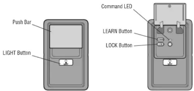
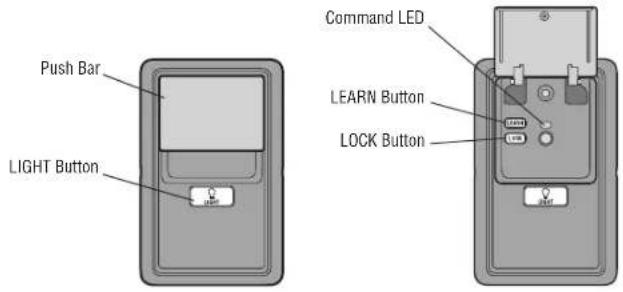
RUSH BARI,
Press the push bar to open or close the door.
will LIGHTS. Ifthe door senses
or is in any position other
Light button garage door opener
Press the LIGHT button to turn the garage door opener lightson or off. When the sensor beam is the one of the wheels, you stand on the button. Once the garage door opener is activated the lightswill turn off after the specified factory setting is 4-1/2 minutes). The LIGHTbutton will not control the lightswhen the
To change the amount of time the garage dooropener lights will stay on:
Press and hold the LOCK button (approximately 10 seconds) until the garage door The time interval is indicated by the number times the garage door opener flashes
• 1 flash is 1-1/2 minutes
• 2 flashes is 2-1/2 minutes
• 3 flashes is 3-1/2 minutes
• 4 flashes is 4-1/2 minutes
To the cycle through each time intervals repeat the step above.
Light Feature
The lightswill turn on when someone enters through the open garage door and the sensor infrared beam is broken.
- Deactivate: Press and hold the LIGHT button (approximately 10 seconds) until the garage door opener lightstum on, then offagain.
- Activate: Start with the garage door opener lights on. Press and hold the LIGHT button
(approximately 10 seconds) until the garage door opener lightsturn off, then c If the command LED is continuouslyblinking, the LOCK feature needs to be deactiva
Operation
Multi-Function Control Panel (continued)
LOCK
The LOCK feature is designed to prevent activation of the garage door opener while still allowing activation from the door control and keyless entry. This feature peace of mind when the home is empty (i.e. vacation).
- Activate: Press and hold the LOCK button for 2 seconds. The command LED will flash as long as the lockfeature is activated and your handheld remote control door at this time.
- Deactivate: Press and hold the LOCK button again for 2 seconds. The command LED will stop flashing and normal operation will resume.
PROGRAM
Any compatible remote controls, wireless keylessentry, accessories can be programmed the garage door opener by pressing the Learn button.
Remote Control and Keyless Entry\*
Pre-programmed remote control included, no need to program the remote.
To add or reprogram a remote control, follow the instructions below.Older Chamberlain controls are NOT compatible,see page 41 for compatible accessories.
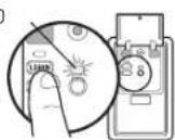
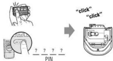
PROGRAM USING THE DOOR CONTROL
- Press the LEARNbutton on the door control to enter Programming Mode.
-
Press the LEARNbutton again, the LED will flash once.
-
Remote Control: Press the button on the remote control that you wish to operate your garage door.
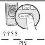
Keyless Entry: Enter a 4-digit personal identification number (PIN) of your cl keyless entry keypad. Then press the ENTER button.
The garage door opener lightswill flash (or two clicks will be heard) when the co-programmed.
1 The command LED will flash once.
2 The command LED will flash once again.
OR
* Not included with all models.
Operation
Remote Control (continued)
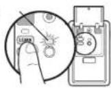
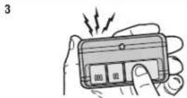
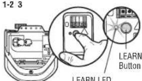
PROGRAM USING THE LEARN BUTTON
- Locate the Learn Button.
- Press and immediately release the Learn button. The Learn LED will seconds. Within 30 seconds...
- Remote Control: Press and hold the button on the remote control that you wish to use. Keyless Entry: Enter a 4-digit personal identification number (PIN) of your keyless entrykeypad. Then pressand hold the ENTER button.
Release the button when the garage door opener lights blink or two clicks are the light lens cover, ensure the antenna wires are hanging straight down.
1-2 3

To watch a video, go to tlnyurl.com/lcsf6xt
HomeLink®
If your vehicle is equipped with HomeLink, a Compatibility Bridge may be necessary for certain vehicles. Visit bridge.chamberlain.com to find out ifa Bridge is needed.
To Erase the Memory
ERASE ALL REMOTE CONTROLS AND KEYLESS ENTRIES
- Press and hold the LEARNbutton on garage door opener until the learn LE glow steady (approximately 6 seconds). All remote control and keylessentrycodes are now era Reprogram any accessory you wish to use.
ERASE ALL DEVICES (Including® enabled accessories)
- Press and hold the LEARNbutton on garage door opener until the learn LE heard. When approximately 6 seconds).
- Immediately press and hold the LEARNbutton again until the learn LED goes are now erased. Reprogram any accessory you wish to use.
Operation
To Open the Door Manually
WARNING
To prevent possible SERIOUS INJURY or DEATH from a falling garage door:
- If possible, use emergency release handle to disengage trolley ONLY when garage door is CLOSED. Weak or broken springs or unbalanced door could result in an open door falling rapidly and/or unexpectedly.
- NEVER use emergency release handle unlessgarage doorway is clear of persons and obstructions.
- NEVER use handle to pull door open or closed. Ifrope knot becomesuntied, you could fall.
- The door should be fully closed if possible.
- Pull down on the emergency release handle so the trolley release arm snaps to the vertical position. The door can now be raised and lowered as often as necessary.
- Pull the emergency release handle toward the garage door opener so the trolley release arm snaps to the horizontal position. The trolley will reconnect the next UP or DOWN operation, either manually or by using the door control or remote control.
Maintenance
Maintenance Schedule
EVERY MONTH
- Manually operate door. If it is unbalanced or binding, call a trained door systems technician.
- Check to be sure door opens and closesfully.Adjust if necessary, see page
- Test the safetyreversal system.Adjustifnecessary, see page 31.
EVERY YEAR
- Oil door rollers, bearings and hinges. The garage door opener does not require lubrication. Do not grease the door tracks.
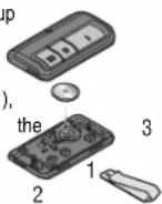
The Remote Control Battery
WARNING
To prevent possible SERIOUS INJURY or DEATH:
- NEVER allow small children near batteries.
• If battery is swallowed, immediately notify doctor.
To reduce risk of fire, explosion or chemical burn:
- Replace ONLY with 3V CR2032 coin batteries.
• DO NOT recharge, disassemble, heat above 212°F (100°C) or incinerate.
The 3V CR2032 Lithium battery should produce power for up to 3 years. If the battery is low, the remote control's LED will not flash when the button is pressed.
To replace battery, pry open the case first in the middle (1), then at each side (2 and 3) with the visor clip. Replace batteries with only 3V CR2032 coin cell batteries. Insert battery positive side up. Dispose of old batteries properly.

NOTICE: This device complies with Part 15 of the FCC rules and Industry Canada's license-ex Operation is subject to the following two conditions: (1) this device may not cause harmful int device must accept any interference received, including interference that may cause undesired op. Any changes or modifications not expressly approved by the party responsible for compliance co authority to operate the equipment.
This device must be installed to ensure a minimum 20 cm (8 in.) distance is maintained below and device.
This device has been tested and found to comply with the limits for a Class B digital devi addition rules and Industry Canada ICES standard. These limits are designed to provide reason against harmful interference in a residential installation. This equipment generates, uses and can frequency energy and, if not installed and used in accordance with the instructions, may cause to radio communications. However, there is no guarantee that interference will not occur in a if this equipment does cause harmful interference to radio or television reception, which can be turning the equipment off and on, the user is encouraged to try to correct the interference to following measures:
• Reorient or relocate the receiving antenna.
- Increase the separation between the equipment and receiver.
- Connect the equipment into an outlet on a circuit different from that to which the receiver is connected.
- Consult the 'dealer or an experienced radio/TV technician for help.
Your garage door opener is programmed with self-diagnostic capabilities. The UP and DOWN arrows on the garage door opener flash the diagnostic codes.
| DIAGNOSTIC CODE SYMPTOM SOLUTION | |||
| Up Arrow Flash(es) | Down Arrow Flash(es) | ||
| 1 | 1 | The garage door opener will not close and the light bulbs flash. | Safety reversing sensors are not installed, connected, or wires may be cut. Inspect sensor wires for a disconnected or cutwire. |
| 1 | 2 | The garage door opener will not close and the light bulbs flash. | There is a short or reversed wire for the safety reversing sensors. Inspect safety sensor wire at all staple and connection points, replace wire or correctas needed. |
| 1 | 3 | The door control will not function. | The wires for the door control are shorted or the door control is faulty. Inspect door control wires at all staple and connection points, replace wire or correctas needed. |
| 1 | 4 | The garage door opener will not close and the light bulbs flash. | Safety reversing sensors are misaligned or were momentarily obstructed. Realign both sensors to ensure both LEDs are steady and not flickering. Make sure nothing is hanging that would interrupt the sensor's path while closing. |
| 1 | 5 | Door moves 6-8" (15-20 cm) stops or reverses. | Manually open and close the door. Check for binding or obstructions, such as a broken spring or door lock, correctas needed. Checkwiring connections at travel module and at the lo travel module if necessary. |
| No movement, only a single click. | Manually open and close the door. Check for binding or obstructions, such as a broken spring or door lock, correctas needed. Replace logic board if necessary. | ||
| Opener hums for 1-2 seconds no movement. | Manually open and close the door. Check for binding or obstructions, such as a broken spring or door lock, correctas needed. Replace motor ifnecessary. | ||
| 1 | 6 | Door coasts after it has come to a complete stop. | Program travel to coasting position or have door balanced by a trained door systems technician. |
| 2 1-5 | No movement, or sound. Replace logic board. | ||
| 3 | 2 | Unable to set the travel or retain position. | Check travel module for proper assembly, replace if necessary. |
Troubleshooting
| DIAGNOSTIC CODE SYMPTOM SOLUTION | |||
| Up Arrow Flash(es) | Down Arrow Flash(es) | ||
| 4 1-4 | Door is moving stops or reverses. | Manually open and close the door. Check for binding or obstructions, such as a broken spring or door lock, correct as needed. Ifthe door isbinding or sticking contact a trained door system is not binding or sticking attempt to reprogram travel (refer to page page 30). | |
| 4 | 5 | Opener runs approximately 6-8" (15-20 cm), stop reverses. | Communication error to travel module.Check travel module connections, replace travel necessary. |
| 4 | 6 | The garage door opener will notclose and the flash. | Slight by reducing sensors are misaligned or were momentarilyobstructed. Realign both sensors both LEDs are steady and not flickering.Make sure nothing is hanging or mounted or interrupt the sensor's path while closing. |
The garage door opener can beep for several reasons:
- Garage door opener has been activated through a device or feature such as Timer-to-Close or garage door monitor, see page page 33.
My remote control will not activate the garage door:
- Verify the lockfeature is not activated on the door control.
• Reprogram the remote control. - If the remote control will still not activate the door check the diagnostic codes to ensure the garage door opener is working properly.
My doorwill not close and the light bulbs blink on my motor unit:
The safety reversing sensor must be connected and aligned correctly before the garage door opener will move in the down direction.
- Verify the safety reversing sensors are properly installed, aligned and free of any obstructions.
My garage door opener light(s) will not turn off when the door is open:
The garage door opener is equipped with a feature that turns the light on when the safety reversing sensors have been obstructed. These features can be disabled using the door control, see page 34. My neighbor's remote control opens my garage door:
Erase the memory from your garage door opener and reprogram the remote control(s).
My vehicle's Homelink ^® is not programming to my garage door opener:
Compatibility Bridge ^TM (not included) may be necessary for certain vehicles. Visit bridge.chamberlain.com to find out if a Bridge is needed.
Accessories
8808CB

8 Foot (2.4 m) Rail
Extension:
To allow an 8 foot (2.4 m) door to open fully.
041A5281-1

Extension Brackets:
(Optional) For safety reversing sensor installation onto the wall or floor.
940EVC Wireless Keypad:

For use outside of the home to enable access to the garage using a 4-digit PIN. Works with ALL Chamberlain openers from 1993-present. MyQ ^® compatible.
953EVC

Remote Control:
Works with ALL Chamberlain openers from 1993-present. MyQ® compatible. Includes visor clip.
8810CB

10 Foot (3 m) Rail Extension:
To allow a 10 foot (3 m) door to open fully.
CLLP1 Laser Parking Assistant:

Park in the right spot every time! A laser beam is activated by your garage door opener and projected on to the dashboard of your vehicle to guide perfect parking.
956EVC Keychain Remote Control:

Works with ALL Chamberlain openers from 1993-present. MyQ® compatible. With key ring.
MyQ® Accessories
PILCEVC MyQ
^8 Remote Lamp Control:
Monitor and control this plug in lamp switch with the MyQ ^® Smartphone App.

WSLCEVC MyQ ^® Interior/Exterior Light

Switch
Monitor and control this wall light switch with the MyQ ^3 Smartphone App.
CIGBUC
MyQ ^® Internet Gateway:
Offers longer range wireless signal than standard Wi-Fi. Plugs into your home router as an optional way to provide MyQ® Smartphone Control for your garage door opener and MyQ® light controls.
Warranty
STOP!
This garage door opener WILL NOT work until the safety reversing sensors are properly installed and aligned.
natural_image
Pure mechanical diagram showing a spring-loaded frame with no text or symbolsContact Information
For installation and service information:
www.chamberlain.com
1-800-528-9131
Before calling, please have the model number of the garage door opener.
If you are calling about a Troubleshooting issue, it is recommended that you have access to your garage door opener while calling.
If you are ordering a repair part please have the following information: part number, part name, and model number.
CHAMBERLAIN® LIMITED WARRANTY
The Chamberlain Group, Inc. ^6 ("Seller") warrants to the first retail purchaser of this product, for the residence in which this product is originally installed, that it is free from defects in materials and/or workmanship for a specific period of time as defined below (the "Warranty Period"). The warranty period commences from the date of purchase.
| WARRANTY PERIOD | |||
| Parts Motor Accessories | Belt | ||
| 1 Year 10 Years 1 year 15 | Years | ||
The proper operation of this product is dependent on your compliance with the instructions regarding installation, operation, and maintenance and testing. Failure to comply strictly with those instructions will void this limited warranty in its entirety. If, during the limited warranty period, this product appears to contain a defect covered by this limited warranty, call 1-800-528-9131, toll free, before dismantling this product. You will be advised of disassembly and shipping instructions when you call. Then send the product or component, pre-paid and insured, as directed to our service center for warranty repair. Please include a brief description of the problem and a dated proof-of-purchase receipt with any product returned for warranty repair. Products returned to Seller for warranty repair, which upon receipt by Seller are confirmed to be defective and covered by this limited warranty, will be repaired or replaced (at Seller's sole option) at no cost to you and returned pre-paid. Defective parts will be repaired or replaced with new or factory rebuilt parts at Seller's sole option. [You are responsible for any costs incurred in removing and/or reinstalling the product or any component.] ALL IMPLIED WARRANTIES FOR THE PRODUCT, INCLUDING BUT NOT LIMITED TO ANY IMPLIED WARRANTIES OF MERCHANTABILITY AND FITNESS FOR A PARTICULAR PURPOSE, ARE LIMITED IN DURATION TO THE APPLICABLE LIMITED WARRANTY PERIOD SET FORTH ABOVE FOR THE RELATED COMPONENT(S), AND NO IMPLIED WARRANTIES WILL EXIST OR APPLY AFTER SUCH PERIOD. Some States do not allow limitations on how long an implied warranty lasts, so the above limitation may not apply to you. THIS LIMITED WARRANTY DOES NOT COVER NON-DEFECT DAMAGE, DAMAGE CAUSED BY IMPROPER INSTALLATION, OPERATION OR CARE (INCLUDING, BUT NOT LIMITED TO ABUSE, MISUSE, FAILURE TO PROVIDE REASONABLE AND NECESSARY MAINTENANCE, UNAUTHORIZED REPAIRS OR ANY ALTERATIONS TO THIS PRODUCT), LABOR CHARGES FOR REINSTALLING A REPAIRED OR REPLACED UNIT, REPLACEMENT OF CONSUMABLE ITEMS (E.G., BATTERIES IN REMOTE CONTROL TRANSMITTERS AND LIGHT BULBS), OR UNITS INSTALLED FOR NON-RESIDENTIAL USE. THIS LIMITED WARRANTY DOES NOT COVER ANY PROBLEMS WITH, OR RELATING TO, THE GARAGE DOOR OR GARAGE DOOR HARDWARE, INCLUDING BUT NOT LIMITED TO THE DOOR SPRINGS, DOOR ROLLERS, DOOR ALIGNMENT OR HINGES. THIS LIMITED WARRANTY ALSO DOES NOT COVER ANY PROBLEMS CAUSED BY INTERFERENCE. UNDER NO CIRCUMSTANCES SHALL SELLER BE LIABLE FOR CONSEQUENTIAL, INCIDENTAL OR SPECIAL DAMAGES ARISING IN CONNECTION WITH USE, OR INABILITY TO USE, THIS PRODUCT. IN NO EVENT SHALL SELLER'S LIABILITY FOR BREACH OF WARRANTY, BREACH OF CONTRACT, NEGLIGENCE OR STRICT LIABILITY EXCEED THE COST OF THE PRODUCT COVERED HEREBY. NO PERSON IS AUTHORIZED TO ASSUME FOR US ANY OTHER LIABILITY IN CONNECTION WITH THE SALE OF THIS PRODUCT.
Some states do not allow the exclusion or limitation of consequential, incidental or special damages, so the above limitation or exclusion may not apply to you. This limited warranty gives you specific legal rights, and you may also have other rights, which vary from state to state.
Repair Parts
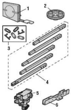
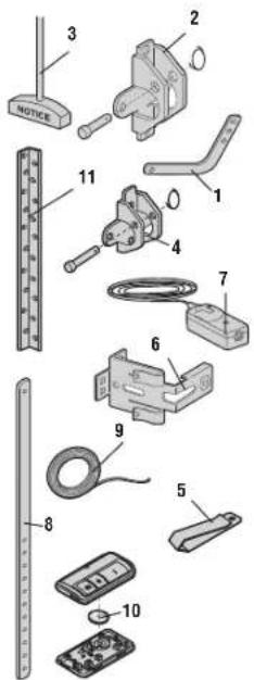
Rail Assembly Parts
| Description Part Number |
| 1 Belt 041A5250 |
| 2 Pulley 144C54 |
| 3 Master Link 4A1008 |
| 4 Rail 041A5665 |
| 5 Trolley Assembly 041C5141-2 |
| 6 "U" Bracket 041D0598-1 |
| Not Shown |
| Wear Pads 183A163 |
| Hardware Bag 041A7920-2 |
Installation Parts
| Description Part Number | ||
| 1 | Curved Door Arm 178B35 | |
| 2 | Door Bracket with Clevis Pin and Fastener | 41A5047-1 |
| 3 | Emergency Release Rope and Handle | 41A2828 |
| 4 | Header Bracket with Clevis Pin and Fastener | 41A5047-2 |
| 5 | Remote Control Visor Clip | 29B137 |
| 6 | Safety Sensor Bracket 041A5266-3 | |
| 7 | Safety Sensor Kit Receiving and sending sensors with wire | 41A5034 |
| 8 | Straight Door Arm | 178B34 |
| 9 | White and Red/White Wire | 41B4494-1 |
| 10 | 3V CR2030 Lithium Battery 10A20 | |
| 11 | Hanging Brackets 12B776 | |
| Not Shown | ||
| Owner's Manual | 114A5064 | |
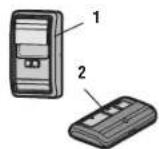
Accessories
| Description Part Number | |
| 1 Multi-Function Control Panel | 041A7185-1 |
| 2 3-Button Remote Control 953ESTD | |
Repair Parts
Garage Door Opener Parts
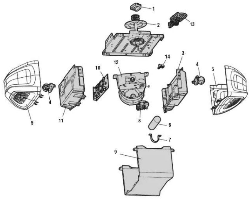
| Description Part Number | |
| 1 Sprocket Cover 041A4371 | |
| 2 Gear and Sprocket 041A4885-5 | |
| 3 End Panel with Light Socket 041A7760 | |
| 4 Light Socket 041C0279 | |
| 5 Light Lens 041D7572 | |
| 6 Capacitor 030B0532-1 | |
| 7 Capacitor Bracket 12A373 | |
| 8 Travel Module 041D7742-7 | |
| 9 Cover 041D8810 | |
| 10 Receiver Logic Board 045ACT | |
| 11 End Panel for Receiver Logic Board with Light Socket | 041D7638 |
| 12 Motor with Travel Module 041A7442 | |
| 13 Line Cord 041B4245-1 | |
| 14 Terminal Block 041A3150 | |
| Not Shown | |
| Wire Harness | 041A7948 |
natural_image
Exterior view of a modern office building (no signage)Préparation
Fixations
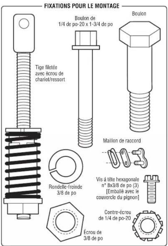
FIXATIONS POUR LA POSE
MATÉRIEL DE
LA COMMANDE
DE PORTE
Montage
OPTION A INSTALLATION AU MUR
natural_image
Diagram of a mechanical clamp or spring device with attached clamps and a handle (no text or symbols)Installation
natural_image
Architectural line drawing of a building facade with window grilles and structural beams (no text or symbols)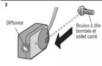
OPTION C POSE AU SOL
natural_image
Technical line drawing of a mechanical assembly with a tool and bracket (no text or symbols)2
3
IL Y A DEUX OPTIONS CONCERNANT LA PRISE D'ALIMENTATION :
OPTION A CÂBLAGE TYPIQUE
natural_image
Line drawing of a two-story house with a garage and windows (no text or symbols)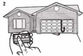
natural_image
Illustration of a house being held by hands, showing front and rear views (no text or symbols)3e Essai du Protector System
AVERTISSEMENT
natural_image
Line drawing of a two-story house with a garage and parked space (no text or symbols)2
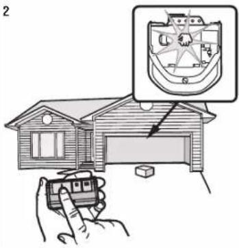
natural_image
Illustration of a house with a hand holding a camera, showing a close-up of a mechanical component inside a boat (no text or symbols present)Fonctionnement
IMPORTANTES CONSIGNES DE SÉCURITÉ


AVERTISSEMENT
Fonctionnement
natural_image
Pure mechanical diagram showing a spring-loaded frame with no text or symbolsCoordonnées
GARANTIE LIMITÉE CHAMBERLAIN
Accessoires
© 2017, The Chamberlain Group, Inc.
The Chamberlain Group, Inc.
300 Windsor Drive
Oak Brook, IL 60523