
GCN 4515 Professional - Stapler BOSCH - Free user manual and instructions
Find the device manual for free GCN 4515 Professional BOSCH in PDF.
| Product type | Pneumatic stapler/nailer |
| Brand | Bosch |
| Model | GCN 4515 Professional |
| Dimensions (H × W × D) | 267 mm × 133 mm × 270 mm |
| Weight | 2.5 kg (according to EPTA 01/2003) |
| Power supply | Compressed air, pressure 5–8 bar, max 10 bar |
| Magazine capacity | Up to 120 nails (coil) |
| Fastener types | Staples and nails on coil, length 19–45 mm, diameter 3 mm |
| Trigger modes | Single shot with safety / Contact burst |
| Impact energy | 37.3 Nm at 6.3 bar |
| Sound level | Sound pressure 92 dB(A), sound power 105 dB(A) |
| Vibration | 3.2 m/s² (uncertainty K=1.5 m/s²) |
| Maintenance and cleaning | Regular lubrication with SAE 10 or 20 oil; cleaning with compressed air |
| Safety | Anti-trigger protection, magazine lock, automatic stop in case of jam |
| Spare parts and repairability | Repair by authorized Bosch service center; original parts available |
| Compliance | EN 792, Directive 2006/42/EC |
Frequently Asked Questions - GCN 4515 Professional BOSCH
User questions about GCN 4515 Professional BOSCH
0 question about this device. Answer the ones you know or ask your own.
Ask a new question about this device
Download the instructions for your Stapler in PDF format for free! Find your manual GCN 4515 Professional - BOSCH and take your electronic device back in hand. On this page are published all the documents necessary for the use of your device. GCN 4515 Professional by BOSCH.
USER MANUAL GCN 4515 Professional BOSCH
OBJ.BUCH-100-001StockPage1FinaS,Mua25,20111.57AM
GCN 45-15 Professional
1
(一)相关风险的分析
tinal
1
中

Robert Bosch GmbH
00
70745 H H E H 8
www.buch-pt.com
1609920X20 2011.00P5/218 UN

de Originalerbsarketan
mng
1
it
mOgnpnnepeeep
da original busing
W
1
Htpumcncnepnncnep
YkpaHcbKa CtopiHa 140
Româna. 148
Быгарский.. 155
Srpski Strana 163
Slovensko Stran 171
Senior Vice President Head of Product
Engineering Certification
Robert Bosch GmbH, Power Tools Division
D-70745 Leinfelden-Echterdingen
General Safety Rules for Pneumatic Tools
4WARNING
Read and observe all safety warnings and instructions. Failure to follow the following safety warnings
and instructions may result in electric shock, fire and/or serious injury.
Save all warnings and instructions for future reference.
Work area safety
- Keep work area clean and well lit. Cluttered or dark areas invite accidents.
Do not operate the pneumatic tool in explosive atmospheres, such as in the presence of flammable liquids, gases or dusts. While working the workpiece, sparks can be created which may ignite the dust or fumes. - Keep children and bystanders away from your workplace while operating the pneumatic tool. Distractions from other persons can cause you to lose control over the pneumatic tool.
Pneumatic tool safety
- Use compressed air of Quality Class 5 in accordance with DIN ISO 8573-1 and a separate maintenance unit close to the pneumatic tool. The compressed air supplied should be free of foreign material and moisture to protect the pneumatic tool from damage, contamination, and the formation of rust.
Check the connections and the air supply lines. All maintenance units, couplers, and hoses should conform to the product specifications in terms of pressure and air volume. Too low pressure impairs the function of the pneumatic tool; too high pressure can result in material damage and personal injury.
Protect the hoses from kinks, restrictions, solvents, and sharp edges. Keep the hoses away from heat, oil, and rotating parts. Immediately replace a damaged hose. A defective air supply line may result in a wild compressed-air hose and can cause personal injury. Raised dust or chips may cause serious eye injury.
Make sure that hose clamps are always tightened firmly. Loose or damaged hose clamps may result in uncontrolled air escape.
Personal safety
Stay alert, watch what you are doing, and use common sense when operating a pneumatic tool. Do not use a pneumatic tool while tired or under the influence of drugs, alcohol, or medication. A moment of inattention while operating a pneumatic tool may result in personal injury.
Use personal protective equipment. Always wear eye protection. Protective equipment such as dust mask, non-skid safety shoes, hard hat, or hearing protection used for appropriate conditions will reduce personal injuries.
Prevent unintentional starting. Make sure that the pneumatic tool is switched off before connecting it to the air supply, picking it up or carrying it. When your finger is on the On/Off switch while carrying the pneumatic tool or when connecting the pneumatic tool to the air supply while it is switched on, accidents can occur.
Remove any adjustment tools before switching on the pneumatic tool. A wrench or key left attached to a rotating part of a pneumatic tool may result in personal injury.
Do not overreach. Keep proper footing and balance at all times. This enables better control of the pneumatic tool in unexpected situations.
Dress properly. Do not wear loose clothing or jewellery. Keep your hair, clothing and gloves away from moving parts. Loose clothes, jewellery or long hair can be caught in moving parts.
If devices are provided for the connection of dust extraction and collection facilities, ensure these are connected and properly used. Use of dust collection can reduce dust-related hazards.
Do not directly inhale the exhaust air. Avoid exposing the eyes to exhaust air. The pneumatic tool's exhaust air can contain water, oil, metal particles and debris from the compressor. This can cause damage to one's health.
Pneumatic tool use and care
- Use the clamping devices or a vice to secure and support the workpiece. Holding the workpiece by hand or against your body will not allow for safe operation of the pneumatic tool.
Do not overload the pneumatic tool. Use the pneumatic tool intended for your work. The correct pneumatic tool will do the job better and safer at the rate for which it is designed. - Do not use a pneumatic tool that has a defective On/Off switch. A pneumatic tool that cannot be controlled with the switch is dangerous and must be repaired.
- Disconnect the air supply before making any adjustments, changing accessories, or placing the pneumatic tool aside. This safety measure prevents accidental starting of the pneumatic tool.
- Store idle pneumatic tools out of the reach of children. Do not allow persons unfamiliar with the pneumatic tool or these instructions to operate the device. Pneumatic tools are dangerous in the hands of untrained users.
- Maintain the pneumatic tool with care. Check for misalignment or binding of moving parts, breakage of parts and any other condition that may affect the pneumatic tool's operation. Have damaged parts repaired before using the pneumatic tool. Many accidents are caused by poorly maintained pneumatic tools.
Use the pneumatic tool, accessories, application tools, etc. according to these instructions. Take into consideration the working conditions and the activities to be carried out. Use of the pneumatic tool
for operations different from those intended could result in hazardous situations.
Service
Have your pneumatic tool repaired only through a qualified repair person and only using original replacement parts. This will ensure that the safety of the pneumatic tool is maintained.
SafetyWarnings for Compressed-air Nailers/Staplers

Wear safety goggles.
Always assume that the pneumatic tool is loaded with fasteners. Careless handling of the pneumatic tool can lead to unexpected shot actuation of fasteners and cause injury.
- When working, hold the pneumatic tool in such a manner that your head and body cannot be injured in case of sudden kickback due to a malfunction of the energy supply or from hard objects/locations in the workpiece.
Never point the pneumatic tool at yourself or at persons close by. Unexpected actuation will expel a fastener, which can lead to injury.
Do not actuate the pneumatic tool until firmly placed against the workpiece. When the pneumatic tool is not in contact with the workpiece, the fastener can bounce away from the fastening point and overload the pneumatic tool.

Do not work on ladders or scaffolds when the actuation system "Contact actuation" is set. In particular, do not move from one fastening location to another, close boxes or enclosures, or fasten transport-securing fix
tures on e.g., vehicles and wagons, via scaffolds, stairs, ladders or ladder-like constructions, such as roof battens. With this actuation system, a fastener will be discharged each time when accidentally applying the pneumatic tool while the discharge lock-off is pressed in. This can lead to injury.
Observe the conditions of the job site. It is possible that fasteners can burst through thin workpieces or be deflected when working in corners or against edges, and harm persons.

Disconnect the air supply, when the fastener is jammed in the pneumatic tool. When the pneumatic tool is still connected to the power supply, it can accidentally be actuated when removing a jammed fastener.
- Use caution when removing a jammed or stuck fastener. The system can be under tension and cause the fastener to be shot or thrust out, while attempting to clear the jam.
Do not use this to pneumatic tool to fasten electrical wiring. It is not suitable for fastening electrical wiring, can damage the insulation of electric cables and thus lead to electric shock and danger of fire. - Never use oxygen or flammable gases as the energy source for the pneumatic tool. Flammable gases are dangerous and can cause the pneumatic tool to explode.
- Use appropriate detectors to determine if utility lines are hidden in the work area or call the local utility company for assistance. Contact with electric lines can lead to fire and electric shock. Damaging a gas line can lead to explosion. Penetrating a water line causes property damage or may cause an electric shock.
The pneumatic tool may only be connected to lines, for which the maximal permissible pressure of the pneumatic tool cannot be ex
16 | English
ceeded by more than 10% for higher pressures, a pressure control valve (pressure reducer) with preceding pressure-limitation valve in the compressed-air line must be installed. Excessive pressure leads to abnormal operation or breakage of the pneumatic tool, which can lead to injury.
Product Description and Specifications

Read all safety warnings and all instructions. Failure to follow the warnings and instructions may result in electric shock, fire and/or serious injury.
Intended Use
The pneumatic tool is intended for connecting work in roofing, encasing, battening, manufacturing wall and ceiling elements, wood facades, pallets, wood fences, noise-reduction walls and boxes.
Only the fasteners (nails, staples, etc.) specified in table "Technical Data" may be used.
Product Features
The numbering of the product features refers to the illustration of the pneumatic tool on the graphics page.
1 Air outlet
2 Handle
3 Air connector
4 Magazine lock
5 Trigger, when working with single actuation
6 Magazine
7 Magazine cover
8 Trigger, when working with contact actuation
9 Outlet
10 Discharge lock-off
11 Thumbwheel for depth stop adjustment
12 Air-connection coupling
13 Supply-air hose
14 Rubber ring
15 Locking pin
16 Actuation lever
17 Actuation spring
18 Actuation bolt
19 Magazine spindle
20 Nail role*
21 Shot duct
22 Feeder hook
23 Guide groove
24 Driver blade
25 Spacer block
26 Button for spacer block adjustment
*Accessories shown or described are not part of the standard delivery scope of the product. A complete overview of accessories can be found in our accessories program.
Noise/Vibration Information
Measured noise values determined according to EN 12549.
Typically the A-weighted noise levels of the pneumatic tool are: Sound pressure level 92 dB(A); sound power level 105 dB(A). Uncertainty
K = 2dB . Wear hearing protection!
Overall vibrational values determined according to EN ISO 20643:
Vibrational emission value ah = 3.2m / s2 Uncertainty K = 1.5m / s2
Technical Data
| Compressed-air nailer GCN 45-15 | ||
| Professional | ||
| Article number | 3601D91C. | |
| Driving forceat 6.3 bar (91 psi) | Nm 37.3 | |
| Actuation systems- Single actuation with safety run | ● | |
| - Contact actuation | ● | |
| Fastener-Type | Nail roleRoofing nails | |
| - L e n g t h | mm | 19-45 |
| -D i a m e t e r | mm | 3 |
| Magazine angle | ° | 15 |
| Magazine capacity, max. | 120 | |
| Engine oilSAE 10, SAE 20 | ml | 0.25-0.5 |
| Internal volume | ml | 362 |
| Rated pressure | bar | 5-8 |
| Connecting thread | " | 3/8 |
| Supply-air hose | ||
| - Max. operating pressure at 20°C | bar | 10 |
| - Inner diameter of hose | " | 3/8 |
| -M a x . h o s e l e n g t h | m | 30 |
| Air consumption per driving procedureat 6.8 bar (100 psi) | l | 1.3 |
| Dimensions | ||
| - H e i g h t | mm | 267 |
| -W i d t h | mm | 133 |
| - L e n g t h | mm | 270 |
| Weight according to EPTA-Procedure01/2003 | kg | 2.5 |
Declaration of Conformity C
We declare under our sole responsibility that the product described under "Technical data" is in conformity with the following standards or standardization documents: EN 792 according to the provisions of the directives 2006/42/EC.
Technical file at:
Robert Bosch GmbH, PT/ESC,
D-70745 Leinfelden-Echterdingen
Dr. Egbert Schneider Dr. Eckerhard Strötgen
Senior Vice President Head of Product
Engineering Certification
ppa. 1. V. Mioy
Robert Bosch GmbH, Power Tools Division
D-70745 Leinfelden-Echterdingen
Connecting the Air Supply
Make sure that the pressure of the compressed-air system is below the maximum permitted rated pressure of the pneumatic tool. Firstly, set the air pressure to the lower value of the recommended rated pressure (see "Technical Data").
When in doubt, check the pressure at the air inlet with a pressure gauge with the pneumatic tool switched on.
For maximum performance, the values for the supply-air hose 13 (connection thread, maximum operating pressure, inner hose diameter, maximum hose length; see "Technical Data") must be observed.
The compressed air supplied should be free of foreign material and moisture to protect the tool from damage, contamination, and the formation of rust.
All fittings, connecting lines and hoses must be dimensioned for the pressure and the required air volume.
Avoid restrictions in the air supply, e.g., from pinching, kinking, or stretching!
Connecting the Air Supply to the Pneumatic Tool (see figure A)
Empty the magazine 6.
(See "Emptying the Magazine", page 18)
For the following worksteps, a fastener can be discharged when interi- or parts of the pneumatic tool are not in the starting position due to repairs, maintenance or transport.
- Connect the air connector 3 with a supply-air hose 13 equipped with an air connection coupling 12.
- Check the proper function by placing the outlet 9 of the pneumatic tool against a piece of scrap wood or wood material, and discharging once or twice.
Changing the Trigger (see figures B1-B2)

Disconnect the air supply before making any adjustments, changing accessories, or placing the pneumatic tool aside. This safety measure prevents accidental starting of the pneumatic tool.
The pneumatic tool can be operated with two different actuation systems. The actuation system is selected by installing the appropriate trigger.
Symbol Trigger Actuation system

Trigger 5 (grey) Single actuation with safety run

Trigger 8 (red) Contact actuation
Removing the Trigger
- Pull off rubber ring 14 from locking pin 15.
- Pull locking pin 15 out of the housing.
- Pull the trigger toward the rear bottom out of the housing.
Mounting the Trigger
- Select the matching trigger to the desired actuation system.
Note: When mounting the grey trigger 5, pay attention that actuation lever 16 is in the correct position (see figure B2).
- Slide the trigger into the housing.
Make sure that actuation spring 17 encloses actuation bolt 18 and exerts force against trigger lever 16.
Align the trigger mounting holes with those of the housing and slide locking pin 15 through the holes.
- Slide rubber ring 14 onto the groove of locking pin 15.
Loading the Magazine (see figures C1-C3)

Disconnect the air supply before making any adjustments, changing accessories, or placing the pneumatic tool aside. This safety measure prevents accidental starting of the pneumatic tool.
Use only original Bosch accessories (see "Technical Data"). The precision parts of the pneumatic tool such as the magazine, the outlet and the shot duct are matched to Bosch staples, nails and brads. Other manufacturers use other steel qualities and sizes.
Using fasteners not permitted, can damage the pneumatic tool and cause injuries.
While loading the magazine, hold the pneumatic tool in such a manner that the outlet 9 is not pointed at your own body or at other persons.
Clean and lubricate shot duct 21 as required and make sure that the magazine 6 is not dirty/soiled.
- Press magazine lock 4 and open magazine cover 7.
The magazine spindle 19 must be adjusted to the length of the nails so that the nails can be rolled off easily into the outlet.
Pull the magazine spindle 19 upward and turn the magazine spindle until it engages in the desired position.
| Nail Length | 19 mm - 32 mm | 32 mm-44 mm |
| Magazine labeling | 3/4-1 1/4 | 1 1/4-1 3/4 |
| Position of magazine spindle | Top | Bottom |
| Rotation direction | Clockwise | Anticlockwise |
- Place the nail role 20 over the magazine spindle 19.
Unwind a sufficient amount of nails, so that the first nail can be positioned in shot duct 21 and the second in feeder hook 22.
Position the nail heads into guide groove 23.
- Shut magazine cover 7 so that magazine lock 4 engages.
When inserting the nail role, pay attention not to damage or de
form the wire winding of the nails. Because of a damaged wire winding or an incorrectly inserted nail role, it is possible that the magazine cover can no longer be correctly shut. This leads to a malfunction of the pneumatic tool.
Operation
Actuation systems
The pneumatic tool can be operated with two different actuations systems:
- Single actuation with safety run
With this actuation system, the discharge lock-off 10 must first be firmly pressed against the workpiece. A fastener is not discharged until the trigger is pulled.
Afterwards, further discharging procedures can only be actuated, when the trigger and the discharge lock-off have first been set back to the starting position.
- Contact actuation
With this actuation system, the trigger must be pulled first. A fastener is always discharged when the discharge lock-off 10 is firmly pressed against the workpiece while the trigger is pressed.
This enables a higher working speed to be achieved.
18 | English
The actuation system is selected by installing the appropriate trigger. (see "Changing the Trigger", page 17)
Starting Operation

Disconnect the air supply before making any adjustments, changing accessories, or placing the pneumatic tool aside. This safety measure prevents accidental starting of the pneumatic tool.
Working with Single Actuation (see figure D)
- Mount the grey trigger 5. (see "Changing the Trigger", page 17)
- Firmly position the outlet 9 against the workpiece until the discharge lock-off 10 is pressed in completely.
- Afterwards, briefly press trigger 5 and release again.
A nail is discharged. - Allow the pneumatic tool to bounce back from the workpiece.
- For another driving procedure, completely lift the pneumatic tool from the workpiece and position it firmly at the next desired location.
Working with Contact Actuation (see figure E)
- Mount the red trigger 8. (see "Changing the Trigger", page 17)
- Press and hold the trigger 8.
- Firmly position the outlet 9 against the workpiece until the discharge lock-off 10 is pressed in completely.
A nail is discharged. - Allow the pneumatic tool to bounce back from the workpiece.
- For another driving procedure, completely lift the pneumatic tool from the workpiece and position it firmly at the next desired location.
- Move the pneumatic tool uniformly over the workpiece by lifting it off and applying it again.
Each time when applying the pneumatic tool while the discharge lockoff is pressed in, a nail will be discharged.
- As soon as the desired amount of nails have been driven in, release trigger 8 again.
Working Advice

Disconnect the air supply before making any adjustments, changing accessories, or placing the pneumatic tool aside. This safety measure prevents accidental starting of the pneumatic tool.
Check the proper function of the safety and actuation devices, and the tight seating of all screws and nuts each time before using.
Disconnect a defective or not properly operating pneumatic tool immediately from of the air supply and contact an authorised service agent for Bosch power tools.
Do not perform any incorrect manipulations on the pneumatic tool. Do not disassemble or block any components of the pneumatic tool, such as the discharge lock-off.
Do not carry out "emergency repairs" with unsuitable means. The pneumatic tool is to be maintained regularly and properly (see "Maintenance and Cleaning", page 19).
Avoid any weakening and damage whatsoever of the pneumatic tool, e.g., through:
- Imprinting or engraving.
Retrofitting measures not approved by the manufacturer,
Guiding along templates manufactured of hard material, e.g. steel, - Dropping on or sliding over the floor,
-Using as a hammer,
Applying any kind of force.
Make sure to check whatever is below or behind your workpiece. Do not shoot nails into walls, ceilings or floors, when persons are behind them. The nails can burst through the workpiece and injure someone.
Do not shoot a nail onto an already driven-in one. This could cause the nail to deform, the nails could become jammed or the pneumatic tool could move uncontrolled.
When the pneumatic tool is used under cold ambient conditions, the first nails will be driven in slower than usual. Once the pneumatic tool has warmed up during working, normal operating speed will be regained.
Avoid blank shots in order to reduce the wear of the impact striker.
For longer work breaks or after finishing work, disconnect the pneumatic tool from the air supply and empty the magazine.
Emptying the Magazine
- Press magazine lock 4 and open magazine cover 7.
- Remove the nail role 20.
- Shut magazine cover 7 so that magazine lock 4 engages.
Adjusting the Depth Stop (see figure F)
The driving depth of the nails can be set with thumbwheel 11.
Empty the magazine 6.
(See "Emptying the Magazine", page 18)
Nails are driven in too deeply:
To reduce the driving depth, turn thumbwheel 11 in anticlockwise direction.
Nails are not driven in deep enough:
To increase the driving depth, turn thumbwheel 11 in clockwise direction.
- Refill the magazine.
(See "Loading the Magazine", page 17)
- Test the new driving depth on a test workpiece. Repeat the worksteps as required.
Clearing Jams (see figure G)
Single nails can become jammed in the shot duct. If this should occur frequently, please contact an authorised service agent for Bosch power tools.
Empty the magazine 6.
Empty the magazine 6.
(See "Emptying the Magazine", page 18)
- Remove the jammed nail. For this, us a pair of pliers, if required.
- When driver blade 24 is extended, push it back into the piston using a lubricated screwdriver or other suitable lubricated object.
Lubricate the shot duct with 2-3 drops of engine oil (SAE 10 or SAE 20). - Refill the magazine.
(See "Loading the Magazine", page 17)
Note: When the driver blade does not return after clearing a jam, please contact an authorised service agent for Bosch power tools.
Adjusting the Spacer Block (seefigure H)
The spacer block 25 enables you to maintain the same clearance, e. g., when fastening roofing shingles.
The spacer block engages approx. every 7 mm:
- Least adjustable clearance to the outlet: 12cm
Largest adjustable clearance to the outlet: 21 cm.
- Press button 26 and move the spacer block 25 until the desired clearance is set.
Transport and Storage
For transport, disconnect the pneumatic tool from the air supply; especially when using ladders or moving in an unusual stance or posture. At the workplace, carry the pneumatic tool only by the handle 2 and with the trigger released.
Maintenance and Service
Maintenance and Cleaning

Disconnect the air supply before making any adjustments, changing accessories, or placing the pneumatic tool aside. This safety measure prevents accidental starting of the pneumatic tool.
If the pneumatic tool should fail despite the care taken in manufacture and testing, repair should be carried out by an authorised customer services agent for Bosch power tools.
In all correspondence and spare parts orders, please always include the 10-digit article number given on the type plate of the pneumatic tool.
Have maintenance and repair work carried out only through qualified persons. This will ensure that the safety of the pneumatic tool is maintained.
An authorized Bosch after-sales service agent will carry out this work quickly and reliably.
Maintenance Schedule
Always keep air outlet 1, discharge lock-off 10 and trigger clean and free of foreign material (dust, chips, sand, etc).
Always store the pneumatic tool disconnected from the air supply and at a clean and dry location.
When not using the pneumatic tool for a longer period of time, cover steel parts with a fine oil coating. This prevents the formation of rust.
Lubricating the Pneumatic Tool (see figure I)
When the pneumatic tool is not connected to a maintenance unit, it must be lubricated at regular intervals:
- For light-duty use 1x per day.
-For heavy-duty use 2x per day.
Apply 2-3 drops of lubricant into air connector 3. Do not apply too much lubricant, which could then accumulate in the pneumatic tool and be emitted via air outlet 1.
Use only the lubricants recommended by Bosch.
SAE 10 mineral engine oil (for use at very cold ambient conditions)
SAE 20 mineral engine oil
Observe all applicable environmental regulations when disposing of old grease and solvents.
Removing Debris/Contamination from Tar (see figure J)
When fastening roofing felt, the pneumatic tool can become contaminated from tar.
For cleaning, use only flame-retardant solvents and clean the discharge lock-off and the outlet with a clean cloth.
Wear protective gloves.
Clean the magazine 6. Remove any plastic or wood chips that may accumulate in the magazine during operation.
Clean the pneumatic tool in regular intervals using compressed air.
| Measure Explanation Action | ||
| Draining the exhaust filter daily. | Prevents the accumulation of dirt/ debris and moisture in the pneumatic tool. | - Open the drain valve. |
| Keeping the lubricator filled at all times. | Ensures the lubrication of the pneumatic tool. | - Fill lubricator with the recommended lubricants. (See "Lubricating the Pneumatic Tool", page 19) |
| Cleaning the magazine 6 and the feeder hook 22. | Prevents the jamming of nails. | - Blow out the mechanism of the magazine/feeder hook daily with compressed air. |
| Ensuring that the discharge lock-off 10 functions properly. | Promotes your work safety and efficient usage of the pneumatic tool. | - Blow out the mechanism of the discharge lock-off daily with compressed air. |
| Lubricating the pneumatic tool. | Reduces the wear of the pneumatic tool. | - Apply 2-3 drops of lubricant into air connector 3. (See "Lubricating the Pneumatic Tool", page 19) |
| Draining the compressor. | Prevents the accumulation of dirt/ debris and moisture in the pneumatic tool. | - Open the drain valve of the compressor tank. |
20 | English
Correction of Malfunctions
| Problem Cause Corrective Measure | ||
| The pneumatic tool is ready for operation but no nails are discharged. | A nail is jammed in the shot duct. - Clear the jam. | (See "Clearing Jams", page 18) |
| The infeed of the nails is blocked. | - Clean and lubricate the feeder hook 22 as required and make sure that the magazine 6 is not dirty/soiled. | |
| The spring of the feeder hook is too week or 22 defective. | - Contact an authorised service agent for Bosch power tools. Have the component replaced there. | |
| The fasteners being used are not permitted. - Use only original accessories. Only the fasteners (nails, staples, etc.) specified in table "Technical Data" may be used. | ||
| The magazine 6 is empty. - Refill the magazine. | (See "Loading the Magazine", page 17) | |
| The nails are discharged very slowly and with too little pressure. | The rated pressure of the compressed-air supply is too low. | - Increase the compressed-air supply. 8 bar may not be exceeded. |
| The driver blade is damaged. - Use only the lubricants recommended by Bosch. (See "Lubricating the Pneumatic Tool", page 19) | ||
| The sealing ring of the piston is worn or damaged. | - Contact an authorised service agent for Bosch power tools. Have the component replaced there. | |
| The buffer is worn. - Contact an authorised service agent for Bosch power tools. Have the component replaced there. | ||
| The length and diameter of supply-air hose 13 do not correspond with the data of this pneumatic tool. | - Use a supply-air hose with the correct dimensions. (See "Technical Data", page 16) | |
| The supply-air hose 13 is bent/creased. | - Correct the bend/crease in the supply-air hose. | |
| The nails are driven in too deep. | The rated pressure of the compressed-air supply is too high. | - Reduce the compressed-air supply. 5 bar may not be fallen below. |
| The depth stop is set too deep. - Adjust the depth stop to the desired depth. (See "Adjusting the Depth Stop", page 18) | ||
| The buffer is worn. - Contact an authorised service agent for Bosch power tools. Have the component replaced there. | ||
| The nails are not driven in deep enough. | The rated pressure of the compressed-air supply is too low. | - Increase the compressed-air supply. 8 bar may not be exceeded. |
| The depth stop is set too high. | - Adjust the depth stop to the desired depth. (See "Adjusting the Depth Stop", page 18) | |
| The length and diameter of supply-air hose 13 do not correspond with the data of this pneumatic tool. | - Use a supply-air hose with the correct dimensions. (See "Technical Data", page 16) | |
| The supply-air hose 13 is bent/creased. | - Correct the bend/crease in the supply-air hose. | |
| The pneumatic tool skips nails or has a too large cycle feed. | The fasteners being used are not permitted. - Use only original accessories. Only the fasteners (nails, staples, etc.) specified in table "Technical Data" may be used. | |
| The magazine 6 is not operating correctly. | - Clean and lubricate the feeder hook 22 as required and make sure that the magazine 6 is not dirty/soiled. | |
| The spring of the feeder hook is too week or 22 defective. | - Contact an authorised service agent for Bosch power tools. Have the component replaced there. | |
| The sealing ring of the piston is worn or damaged. | - Contact an authorised service agent for Bosch power tools. Have the component replaced there. | |
| Frequent jamming of nails in the shoot duct. | The fasteners being used are not permitted. - Use only original accessories. Only the fasteners (nails, staples, etc.) specified in table "Technical Data" may be used. | |
| - Contact an authorised service agent for Bosch power tools. | ||
| The driven nails are bent. | The driver blade is damaged. - Contact an authorised service agent for Bosch power tools. Have the component replaced there. | |
| Contrary to working with normal operat-ing speed, the nails are not driven in deep enough at higher operating speed. | The interior diameter of the supply-air hose is too low. | - Use a supply-air hose with the correct dimensions. (See "Technical Data", page 16) |
| The compressor is not suitable for fast operating speeds. | - Use a compressor that is sufficiently dimensioned for the number of connected pneumatic tools and the operating speed. | |
Accessories
For more information on the complete quality accessories program, please refer to the Internet under www.bosch-pt.com or contact your specialist shop.
After-sales Service and Customer Assistance
Our after-sales service responds to your questions concerning maintenance and repair of your product as well as spare parts. Exploded views and information on spare parts can also be found under:
www.bosch-pt.com
Our customer service representatives can answer your questions concerning possible applications and adjustment of products and accessories.
Great Britain
Robert Bosch Ltd. (B.S.C.)
P.O.Box 98
Broadwater Park
North Orbital Road
Denham
Uxbridge
UB95HJ
Tel. Service: +44 (0844) 736 0109
Fax:+440844)7360146
E-Mail: boschservicecentre@bosch.com
Ireland
Origo Ltd.
Unit 23 Magna Drive
Magna Business Park
City West
Dublin 24
Tel. Service: +353 (01) 466 67 00
Fax: +353 (01) 4666888
Australia, New Zealand and Pacific Islands
Robert Bosch Australia Pty. Ltd.
Power Tools
Locked Bag 66
Clayton South VIC 3169
Customer Contact Center
Inside Australia:
Phone: +61 (01300) 307 044
Fax: +61 (01300) 307 045
Inside New Zealand:
Phone: +64 (0800) 543 353
Fax:+64(0800)428570
Outside AU and NZ:
Phone: +61 (03) 9541 5555
www.bosch.com.au
Republic of South Africa
Customer service
Hotline: +27 (011) 6519600
Gauteng - BSC Service Centre
35 Roper Street, New Centre
Johannesburg
Tel.: +27 (011) 4939375
Fax:+27(011)4930126
E-Mail: bsctools@icon.co.za
KZN - BSC Service Centre
Unit E, Almar Centre
143 Crompton Street
Pinetown
Tel.: +27 (031) 7012120
Fax:+27(031)7012446
E-Mail: bsc.dur@za.bosch.com
Western Cape - BSC Service Centre
Democracy Way, Prosperity Park
Milnerton
Tel.: +27 (021) 551 25 77
Fax:+27(021)5513223
E-Mail: bsc@zsd.co.za
Bosch Headquarters
Midrand, Gauteng
Tel.: +27 (011) 6519600
Fax:+27(011)6519880
E-Mail: rbsa-hq.pts@za.bosch.com


22 | Français
Disposal
The pneumatic tool, accessories and packaging should be sorted for environmental-friendly recycling.
Observe all applicable environmental regulations when disposing of old grease and solvents.
If your pneumatic tool can no longer be used, deliver it to a recycling centre or return it to a dealer - for example, an authorized Bosch after-sales service agent.
Subject to change without notice.
Français
Senior Vice President Head of Product
Engineering Certification
ppa. Meuta i.v. Mojgcu
Robert Bosch GmbH, Power Tools Division
D-70745 Leinfelden-Echterdingen
Robert Bosch (France) S.A.S.
Senior Vice President Head of Product
Engineering Certification
Paa Maae i. Nooyea
Robert Bosch GmbH, Power Tools Division
D-70745 Leinfelden-Echterdingen
Dr. Egbert Schneider Dr. Eckerhard Strötgen Senior Vice President Head of Product Engineering Certification

v( x,y) = 0
Robert Bosch GmbH, Power Tools Division D-70745 Leinfelden-Echterdingen Leinfelden,25.03.2011
Montagem
Colocar as cabecas dos pregos na ranhura de guia 23.
Senior Vice President
Head of Product
Engineering
Certification
ppa.
Senior Vice President
Head of Product
Engineering
Certification

Robert Bosch GmbH, Power Tools Division
D-70745 Leinfelden-Echterdingen
Senior Vice President
Engineering
Dr. Eckerhard Strötgen
Head of Product
Certification
Pp. 146
Robert Bosch GmbH, Power Tools Division
D-70745 Leinfelden-Echterdingen
Bosch Service Center
Telegrafvej 3
2750 Ballerup
Tel. Service Center: +45 (4489) 8855
Fax: +45 (4489) 87 55
E-Mail: vaerktoej@dk.bosch.com
Bortskaffelse
Senior Vice President
Head of Product
Engineering
Certification

v( x,y) = ( x ,2)
Robert Bosch GmbH, Power Tools Division
D-70745 Leinfelden-Echterdingen
Tilloppsslangens inre diameter ar for liters.
Bosch Service Center
Telegrafvej 3
2750 Ballerup
Danmark
Tel.: +46 (020) 414455
Fax:+46(011)187691
Avfallshantering
Senior Vice President Head of Product
Engineering Certification
ppa.
Robert Bosch GmbH, Power Tools Division
D-70745 Leinfelden-Echterdingen
Senior Vice President
Head of Product
Engineering
Certification
Pae.
Robert Bosch GmbH, Power Tools Division
D-70745 Leinfelden-Echterdingen
Senior Vice President
Engineering
Dr. Eckerhard Strötgen
Head of Product
Certification
ppa. 1. V. Mioyceu
Robert Bosch GmbH, Power Tools Division
D-70745 Leinfelden-Echterdingen
Senior Vice President
Engineering
Dr. Eckerhard Strötgen
Head of Product
Certification
Paa.
Robert Bosch GmbH, Power Tools Division
D-70745 Leinfelden-Echterdingen
Bosch San. ve Tic. A.S.
Ahi Evran Cad. No:1 Kat:22
Polaris Plaza
80670 Maslak/Istanbul
Müsteri Danismani: +90 (0212) 335 06 66
Müsteri Servis Hatti: +90 (0212) 335 07 52
Tasfiye
Senior Vice President
Engineering
Dr. Eckerhard Strötgen
Head of Product
Certification
Paa
Robert Bosch GmbH, Power Tools Division
D-70745 Leinfelden-Echterdingen
Robert Bosch Sp. z o.o.
Dr. Egbert Schneider Senior Vice President Engineering
Dr. Eckerhard Strötgen
Head of Product
Certification

- V.NCO3
Robert Bosch GmbH, Power Tools Division D-70745 Leinfelden-Echterdingen Leinfelden, 25.03.2011
Montáž
Pripojeni na zdroj vzduchu
Presvedcete se, ze tlak instalace tlakovhe vzduchu neni vets nez maximni priustn y jmenovity tlak pneumatickeho na radi. Nejdrive nestavte tlak vzduchu na spodni hodnotu doporueneho jmenoviteho tlaku (viz, Technicka data").
Ve spornych pripeadech zkontrolujte tlak na vstupu vzduchu pomoci manometru pri zapnutem pneumatickem naradi.
Pro maximali vykon museji byt dodrzeny hodnoty pro privodni hadici 13 (pripojovaci zavit, maximali provozni tlak, svetlost hadice, maximali delka hadice; viz „Technická data").
Vymena spousté (viz obr. B1-B2)

Pferuste zasobovani vzduchem drive, nez pristoupite k serizeni stroje, yvmene dilu prisluenssti nebo pneumaticke naudi odlozite. Toto preventivni opatfeni zarani neuyslnemu startup pneumatickeho naudi.
Bosch Service Center PT
K Vapence 1621/16
692 01 Mikulov
Senior Vice President Head of Product
Engineering Certification
Paa.
Robert Bosch GmbH, Power Tools Division
D-70745 Leinfelden-Echterdingen
Senior Vice President
Head of Product
Engineering
Certification
ppa. 1. V. Nogycu
Robert Bosch GmbH, Power Tools Division D-70745 Leinfelden Echterdingen Leinfelden, 25.03.2011
Be30nachOCTb THeBMaTHueCkHX HnCTpyMeHToB
IpHMeHrTe CxAby 5-TO KAcca KaecTa IIO DIN ISO 8573-1 HnAHBMyAaBbHb6AOK B03AxyoTOaROTBKN B6AN3 INHEMOHNCTpyMeHTA. AAn3aunTbI INHEMOHNCTpyMeHTa OT IOBpeXeHH, 3arpa3HeHHN O6pa3OBaHH N KoppO3N IIOaBaembl CxAby BO3Ax DOJXe6bI OUYHcEOTIOCTOPOHHX YACTMII BAaM
PioBepaTe PnHCOeHNHeHH HANHH THTAHN.Bce 6AOKH BO3yXIOAOFTOBKMyTbI NIIAAHm DOAXHBI 6bITb paccHTaHbHa AaBHeHne I paCXoA Bo3yxa corAcho TexHnEeCKHM DaHbM.Hn3Koe AaBHeHne OTPuATaeHo BnREt HaФyHKmIO THEBMOnHCTpyMeHTA, 3ABiUHEHOe DAaBHeHne MOKeT PnBcETK IOBpeXeHNm I TaBMaM.
3aunuai Te 1Aanrno TnepeHnOB, nepexHMOB, pactbopHTaeH N OCTpbix KpOMOK. 3auuuaite WAAHn OT BO3eHCTBn IOBbIeHHbIX TemTepatyp, Maa H BpaauioxxCsTeaJe. He MeDAEHHO 3aemeHnTE TOBpeXeHHb IaAH. DepeKTHa AHHN INTHAHMOKET PIPBEcTN K6bIOeMy BOKpy Ce6ra aHaHry CkATORO BO3dYxA nCTab PnPHHOITpAM. POAHrTaB BO3dYX TbALhAN CTpykKa MOKET BblBaT TBXeAEI TpABMbI Ia3.
CAeAHTe 3a TEM, YTO6bI XOMYTHKN UAAHROB 6bIAH Bcerda KpeNko 3aTnHYtbl. Cλo6 3aKpEeHHbIe HAI NIOBPEXAEHHbIe XOMYTHKN UAAHRA MOrY CTAtb PIPINHHOYTEKHNBO3yxa.
Be30TnachOCTb AIODeE
Bybte BHHMATEaBbIMn,CAeHNTe 3a TEM,TO BblAeae TpoDyMaHHO HauHnHaTe paOby CTHEBMOHCTpyMeHTo. He
Pycckn | 133
TIOAB3yITeCb THEBMOHCTpyMeHTOM BYCTAOM COCTOHHH HAN, ECAN BbI HAXoADHeCb TIOA BAHHHem HApKOTKOB, CTMPTHbIX HAHTKOB HAN AEkapCTB. OAnH MOMeHT HeBHMMATEbHOCTN TPn pa6ote C TtHEBMONHCTpyMeHTOM MOKET TIPNBcETN K cepbe3HbIM TpaBMam.
IIpHMeHnTE HANBnAaHbIe CpeCTBa 3aunTb I BcerDa 3aunThbOcKn. IIpHMeHHe nCpeCTB HANBnAaHbHO 3aunTbI, KaTO TbIae3aunTHoro peCtnpaTopa, cteuObyBN, 3auNTHO IIIaMa, CpeCTB 3auNTbIOprAHOB CAYxa, B 3aBnCHMOCTN OT BnA uYCAOBn pa60TbIC INEBMOHNCTpymENTOM, CHNKaET PCK TpaBMPOBAHH.
IpeoBpaaHHe npAmepeHHoe Bkauohne. Ipea IOKluoyenHm THEBMONHCTpymeHTa K Bo3dyxOCH6xEHnIO, TepeTcM, KaK BbI BO3bMetE erO B pyuN ItpaHCTOpTHPOBkoIpoBepBeero BBkAUoyehHOcoCTOHHe.YdepXaHHe TaBaHa BblAouatee IIpyeHOce TIEBMOHNCTpymeHTa HAI TOdKluoyehNE BkAUoyEHOrTO TIEBMOHNCTpymeHTa K NCTOCHNY BO3dyxa YpeBaTo HecacthBIM CAYaAMH.
IpeBkauyHem THeBMOnHCTpyMeHTa y6epTe yctahOBouhbl HnchtpyMeHT.YCTaHOBOUHy HnHCTpyMeHT,HAXOARuNCBA BO BpaauoueCra Yactn THeBMOnHCTpyMeHTa,MOXETpNBECTK TpaBMam.
He TpeoueHHBaIte c6a.Bcerda3ahmaitytoHBOE IOAOXEHNE HBCERdA BbIDepKBAHTe paBHOBcH.EYTOOHBOE IOAOXEHNE H COOTBETCTBYIOOEE IOAOXEHNE KOPNYCA I03BOARt Bam AUYUe CnpabITbcrC INHEBMONHCTpyMeHToM B HeOXnAHbIX CNTVAuNX.
Hochte noxoady0 odexy. He hochte wnpokyo odexdy n ykpaawnna. Aepknte BOaocbl, oedxy n nepatkn B ctopone OT ABHXyunxc qactei. uPOKA OEDxa, ykpaewnna HAN DAHHbIe BOACbI MOrT 6bTb 3aTHyTb BpaauoMHNC qACTHM.
PnHaHnH B03MOxHcTH yCTaHOBKn TbIaeOTcAcbIbAounx H TbIaeC6OpbHix yCTPOJcTB PTOBepRte Nx PnPCoEHNHe H TpABNaHbOe HCToAb3OBaHne. NcIOA3OBaHne 3TNX yCTPOJcTB CHNKAET OTACHOCTbOT B03AEChTBnAM
HeBbIXaIeOTpa6oTAHbBI03Ayx.ClaIaHTe3aTeM,YTO6bI OTPa6oTahHbBI03AyxHEIOIaADABRtAA3o.OTpa6oTahHbBI03Ayx H3THEBMONHCTpyMeHTaMOKETCOePjXbTbOy,MaCLO, METaANueCKHeCAHTuBn3aTpRAHHeHHIOIaIOUHeN3 KOMPiPeCCopa.3ToMOKETHMETbBpeHOEBAINHHeHa3doPObBe.
TuatalebHoe 06xoxkdeHHe CTHEBMOHCTpyMeHTAMN HXTIpaBbHoe npMmeHHe
AyaepKHaBnHnHOtOpblEtAaHnTOaB3yTeCb3axHHbIMN yctpoHCTBaAMnHANTHCKAm. YepKHaBaaTeaBpyKOHNTPHXMaeeKteLy,BbHe MoKeTe HaExxoYipPaABTbTIEBMOnHCTpyMeHTOM.
HeIpepykaTe THEBMONHCTPymENT. HcnoAbyte DaBaae pa6OtbI IpeHa3HauHHbI DA 3TOI THEBMONHCTPymENT.C IOxOaIMM THEBMONHCTPymENTOM Bpa6OtaE Auyue H naExKee B yKa3AHOM dHaTnAOHO MOHOCHTN.
He TIOb3yItecB THEBMOHNCTPymeHtOM C HEnCITpaBbIM BbIKAOYATEAm. THEBMOHNCTPymeHT, KOTOpB He TEIOAAETCR BKAIO YEHINHOAN BbIKAOYEHINO, OTaCeH N DOXKeH 6bTb OTpEMOHNTPOBAH.
OTKIAOHTeIOaCyCKaTOroBO3aYxdoHauaHaHCTPOIKN HhCTpymEnA,CMehbOCHACTKNHANTPeXdYeEMBbITyCTNTb THeBMOnHCTpymEnH3pyk.3TaMepaTIpeOCTOPOXHOCTNIpeOToBpa- 1aET HePeDnHaMepeHHbI NycTHHeBMOnHCTpymEnA.
XpaHHTe HcHToB3yEmbI THeBMOnHCTpyMeHtB B HeOcraEaOM MAA DeTe MeTe. He pa3peWaiTe IaB3oBaTbCra THeBMOnHCTpy
MEHOM ANUAM, KOTOpbHe 3eHaKOMbI C HMM HAN He YHTaAH NaCTOaHx HHCTpyKu. THeBMOHcTpyMeHbI OaChbI B pyKaX HEOTbTHbIX AML.
TuaTeAho yXaXbHaIe 3a THeBMOHCTpyMeHToM. PIOBepaTe 6e3yTpueHyIO FyHKUIO H XOa DBNKUHXCra Cacte TnHEBMOHCTpyMeHTA, OTCYCTBNE IOAMOK HN TOBpeKaENH, OTPuTaEhHO BAHIOxH Na FyHKUIO THeBMOHCTpyMeHTA. IOBpeKaENHbIE qACTH DOJXHBi 6bITb OTpEMOHTHPOBaHbI DO HcTOA30BAHINn THeBMOHCTpyMeHTA. IAOxoe 0cCaXyBaHHe THeBMOHCTpyMeHTOB RAHETC pINHHo 6oABWOr OHCaa HeCcaTHbIX CAUYAEB.
TIPMHENIe THeBMOHCTpyMeT, PnHaAeXKHOCTN, pa6OyHe HNCTpyMeHTb H.T.B COOTBETCTBH N CHACTOaHHMHNHCTpyKunm. YuHTbBAHTe PnH 3OM yCAOBH N BHa pa60tBu, IcNoIb3oBaHHe THeBMOHCTpyMeHTa AAR APYHX, HETpeAycMOTpeHHbIX pa60T MoKet TPINBECTN K OTAChbl CHTaUHM.
CepBnC
Pemont Baewero THEBMONHCTpyMeTA TOpyaTe ToAko KBaHnHPOBAHOMY TepcoHaA HToAko C HTOA3OBAHEM opHHaHbIX 3aTuaCTe.3TIm ObecTneHbaetc8630NaCHOCTb THEBMONHCTpyMeTA B AaBHeuEeM
Yka3aHnI NO TexHKe 6e30NaCHOCTH AAR THEBMATNueCkHX CkO6o-N rB03e3a6NBbIX HHCTpymENTOB

Hcnoab3yIte 3aunTHbIe ouKN.
Bcerda HxOAnTe H3 TOR, YTO B INHEBMONHCTpymente HaxoAnTcKpeKeHHMATEpHaA. He6peXHoe o6paueHHe cTIHEBMONHCTpyMeHTOM MOKeT IIPMBeCTn K HeoxKaDaHHOMByBbTAaKNBaHmIO KpeIeXHOrO MATEpHaA, BCaeACTBne Yero Bbl MoKeTeTIaUyHTb TpaBMbl.
AepKHe IINHEMOHCTpyMeT BOPa60tB Tak, qTO6bI BbI He MOrAN IopAHHTB rOAOBY H TEAO IIPN BO3MOXHOM pHKOWETE BCAEDCTBME HNCIPABHOCTe B CETH TITAHN HAN HATAANKBAHNIHCTpyMeHTA HA TBEPAbIe MecTA B 3AROTOBKE.
He HATpABAAHTe THeBMOHCTpyMeTHa Ce6n HApYHX AIODeHAXOaIuXcraIOAM3OCh.BCAEACTBNE HeoXnAHHOro IyckaHHCTpyMeHTa BbITaAKBaETcKpeNEXHbMaTePmaA,TO MOxETTPHBECTN K TpaBMam.
He BKAIOaHTe THeBMOHCTPymENT, Toka BaIbI He IpiHCTabHn erO npouHO K3aTOBKe. ECAH MExdy THeBMOHCTPymENTOM H 3aTOBKOH HET KOHTAKT, KpeIXKhbl MaTePHaMA MOKET OTCKOHTbOT MecTA KpeIaeHHN II PnPBecTH K IIpeERpy3E THeBMOHCTPymNTA.

He pa6oTaIe Ha IecTHNuax HAN IIOMOCTax, ECAN BkIoUeyHa CnCTema CnTyCKA KOnKTbHc Ncyck.B VacTHOCTH,3aIpeMaETC npeMeaATbC HAnOMOCTax, AecTHNuaX, CTpeMnKAX HAN IOo6bIX KOHCTpyKunX, KaK HAp., 06peWetKAX Kpbl, OT OADHO MecTa pa6OtB KApYrOmy, 3aKpbIbAt bIuKNH HAn TepEROPoAKH HAN OCHaATb, HApT, TpaHCToPTbIe CpeACTBa HAN BarOHb, TpaHCToPTbIMH fHKCaTOPaAM. ECAH Bb II pIH 3TOI CNCTeME CnTyCKa CnayHIO pINCTaBHT INHEBMONHCTpymEHT K 3aROTOBKe Ipi HAXATOM IpeDOxPAHNTAE CnYCKBOrO KpOHyKa, KaKbIpa3 6yDet BbITAAKHBATCB KPeTIeKhBm MatePnaA. 3TO MOKET IPIBecTH K TpaBam.

134
Pycckn
CaeHTe 3a yCaOBHMn Ha MeCe pa6oTb. KpeNekHbM MaTePhnMOKETIPO6BnBaT ToHKHe 3aToOBKN Hn Ipi Pa6Oax Ha yrAax H KpaX3aTOBOK OTCKaKNBaT pKoWetOM paHHTb AHOeH.

OTKAOUHTe ChabxHHe Bo3dyxa,ecAN KpeTExhbl MaTePha3actpB THeBMOnHCTpyMeHT. EcAn IHEBMOnHCTpyMEHTIOAIAOeHNK HCTOHTNkyIITAHNA,IPIN ydaAeHHN 3actpABWero KpeTExHOro MaTePhaA OH MOXET 6bIb CAYaHNO pINBeDeH B DeIECTBNE.
ByTe octopOKHbI pIN BbITaRbAHm 3actpBwero KpeTexHoMaTePnHa. CNTema MoKET HAXOHTbCRA Ha B3BOe H KpeTexHbIMATEpHaAM MoKET 6bITb BbTOAkhYt C CHAO, KOgA Bb BYTe IPOBoBaTbBbTAUHTb eO.
He HcnoB3yIte 3OT INHEBMOHCTPymeH DAA3aKePeTAEHH 3AeKtponpoBOxN. OH He IpeHa3HaueH AIN POKnAaKn 3AeKtponpoBOaKN, MoKET IOBpeNTb HIOARuHIO AeKtPOKaBeA IN PnBecIn K 3AeKtPNueCKOMY ydApN ONaCHOCTIOXapa.
HkoRaHe HcnoB3yIe KNCLOpOHaH TropOue Ra3bI B KaueCTBe HcToHHKa 3hePrrn DAA THeBMOnHCTpyMeHTa. TOpOue Ra3bl OTAChbl, OHMOYrT CtaTb PnPHNO B4pbBa THeBMOnHCTpyMeHTa.
PnHMeHHe CoOBETcBMyHne MetaAONCKateAH HAXOXeHHN CkpbItbIX ChCTEm 3AEKtpo-, r30-N BOOCHa6xEHn HAn ObaaHteCb 3a CTPaKBoB MecTHOE TpeADPHATHE KOMMyHaBHOr CHa6XeHH. KOHTAKC 3AEKTPoIPBOAOKO MoKet TPnBECTN K ToXapy N ToPAxeHHO 3AEKTPoTOKOM. TOpBXeHHe ra3oIPBOOda MOxET PnBeCTN K B3pbyI. TOpBXeHNE BOOIPBOOBA BeET K HaHeCEHNO MaTePhAIBHO rYueP6a.
PnKIOAHTe THeBMOHCTpyMeT TObKO Tpy60npoBOaM, B KOTOBx MAKCHMaABHO DToYCTHMoe DAITHEBMOHCTpyMeHTa DaBAAHHe He MOKET 6bIb TpeBbIeHo 6Oae CHe HA 10%; IIpN 6oAbeM daBAAHm Hpy60npoBO cKaTO BO3aXha HeoXaHMo OcHaCTHTb peryAHTOPOM daBAAHHe (peykuHHbIM KaAHAOM KaaTahOM OrpaHueHH DaBAAHHe. 3aBbIeHHOe DaBAeHne MOKET CTaTb PnHHoC6oEB Ba6ote HAN TIOBpeXeHH NTHBMONHCTpyMeHTA, YTO MOKET IINBECTK TpaBMAM.
OtncaHne ppoAkykTa n ycAyr

IpoHTe BCE yka3aHn HNCTpyKuHn T0 TexHnKe 6e3oTachochty.UTyueHHB OTHOweHHYka3AHn H NHCtpyKuHn IO TexHnKe 6e3oTachocHTM MGYT CTaTB IpHuHnIopaxHeHn 3AekTpueckHM TOKOM,IOxapa H TkXeAbx TpaBM.
TIPMHeHHe ITO Ha3HaueHHIO
THeBMOnHCTpyMeHTIpeHa3HaueHAA CoeMHHeHH 3AeMeHToB IPN KPOBeAbHbIX paOTox,06uHbKe DOCKaMM H CToPHTAcBcTe BOpEWeK, a TaKcE IPN H3rTOBtAEHHN CTHeHHbIX/KPOBeAbHbIX 3AeMeHToB, DepeBHHbIX PaCaADoB, PAAET, DepeBHHbIX 3a6OpOB, 3ByKOH3oAUNHOHbIX CTEH RnIKOB.
Pa3peaetcHCTIOAe3OBaTbTObKO KpeIeKHyMaTePHaA(TBO3M,CKo6bnt.,yka3aHHbB Ta6Amue《TexHnueckne DaHHBe》
H306paxeHHbIe coCTaBhbIe qactn
HymepaunI ppeCTaBaeHHbIX KOMTOHEHOB BblIOAHeHa IIO H3o6paKeHHIO THEBMONHCTpyMeHTA HA CtpaHnue C HNOCTpaHnM.
1OTBepCTHeAAR BbIXOa BO3yxa
2PyKoTka
3Tatpy60kAIAIOABO4BaBO3yxa
43aTbOp mara3Ha
5CnyckoBOKKPQOKA4apa60TcOAHOpa3OBbIMCTyckOM
6 Mara3HH
7 KpbiIka MaIa3Ha
8CITyCKOBOHNKPOHOKA4aPb0T C KOHTaTHbIM CITyCKOM
9 BbIXoADHoe OTBepCTHe
10IpeaoxpaHnteAcbnyckBOrO Kpouka
11KoLecnKOdHaHacPoHNOrpaHnHTeRAIy6NHBi
12 BbIcTpoAeHCTBvOuaaMyΦTa
13 ⅢAANTIOaHbO3dyxa
14 Pe3HHOBoe KOAbO
15 CTOnOpHbI WHTnOFT
16 Pbyar cnyckOBoro kpoUka
17 PnyxHa cnyckoBOro KpOuKa
18 BoAT CnyckoBOro KpOuKa
19IINHDeAbMara3HaHa
20 06Oma rB03dE
21 KaHaA BbTaAKnBaHnA
22KpOyOKAIAIPOaHrBO3eI
23 HanpaBAAIOJIINIa3
24 Boek
25 PaCIOHbI 3AeMeHT
26 KhoTka DnH aactpoKn paCnpHOro 3AeMeHTa
HIO6paekHNHeI HAI ONTHCAHNIIE TpHHaAeXKHOCTHE XBOADT B cTAHApTBLH 0bEBmTOCTABKN. IIOAHBI ACCOPTMEHT PpHHaAeXKHOCTe Bbl HAeTe B hauwE Tporprampe prrnAAeXKHOCTe.
TexHHueckne daHHble
AaHbIe TIO WMy H Bn6paunu
YpOBeHbIyMaOTpeAeENBCOOTBetCTBnC eBpOTeckoHOPMOEN12549.
A-BBWeHbIyPOeHbWMyaOTINHEMOHNCTpyMeHTaCOCTaBAET 06bHuO: yPOeHb3ByKOBOrO DaBHeHHN92A5(A); yPOeHb3ByKOBOmOuHOCTn105A5(A).TOrpeuHocTbK=2A5.
OeBaIte HauHHNK!
CymapHbIe 3HaeyHn BIn6paunn IOnyueHbB COOTBETCTBN C EN ISO 20643:
Bbpaanra ah = 3,2M / c2 nporpeunoctbK=1,5M/c²
3aBAAeHHe 0 COOTBeCTBHN
CE
CTOHONOTBCTBEHHOCTBMO3aBAEM,YTOOTHCANHBIBpa3deAE
《TexHnueckneDaHHbe》IPOADKTCOOTBeTCTBYETHNKECADEIOUIM
CTAHPATAM HAN HOPMATNBHMIDOKyMENTAM:EN792coraacho
TNOAOKeHHAMDapeKTMBbl 2006/42/EC.
TexHHuecka DOKyMeHTaUHa:
Robert Bosch GmbH, PT/ESC,
D-70745 Leinfelden-Echterdingen
Dr. Egbert Schneider
Senior Vice President
Engineering
Dr. Eckerhard Strötgen
Head of Product
Certification
ppa. 1. v. nuoyceu
Robert Bosch GmbH, Power Tools Division
D-70745 Leinfelden-Echterdingen
IPhcoeAHHeHHe HHTaHHcKaTbIM BO3dYOM KTHHEBMHOHCTpyMeHTy (cm.phc.A)
-OnopoxhnteMaar6
(cM.《OnopoxHeHHeMa3Ha》,cTp.137)
IpiNIOcAeDyOuX npoHx Opeaunx Bo3MOxHO BbItaKNBaHne KpeTExHO mATEpnaaaa, eCn BCaeCTBne pemOHTHbIX pa6OT n pa6OT IO TeXHHueCKOMY oCbAYKBAHHIO HN BCAECTBNE TpaHCIOPTHPOBKN BHYTpEHHe DEtaNN IHEBMONHCTpyMeHTa 6dyT hAXoAHtCB He B NCXODHOM IOAOxEHHN.
-CoeaHHHTe TATpy60K AINIOB0A BO3yxa 3 COIaHrOM AINIOaHBO3yxa13, OCHaENHHbIM 6bICTPOeHCTBYUOe MyfTOJ 12.
-1P0BepbTe 63yTpeHocb paOToI THeBMOnHCTpyMeHa, TpNCTaHBERo BixOaHbIM OTBePCTHEM 9 K KYCKY ApeBecHbI HAn DepeBraHHOrMaTePnAa H BcTpeANB OINH HAn Dpa p3a.
3aMeHa cTnyckoBOrO KpUQKa (cM. pHc. B1-B2)

OTKIOaHTe IIOaUcXaTOro BO3aXa DO HAaA HAcTPOHnHCTpyMeHTa, CmEhblOChACTKN HAnItpExKe AEM BbITyCTNtBIIHEBMOnHCTpyMeHT Hpyk.3Ta Mepa IIpeOTOPOXHOCTINIpeOToBpaauet HeIpeHaMepeHHbI Iyck IIHEBMOnHCTpyMeHTa.
THEBMOHCTPYMEHT MOKET pa60TaTc ABYMa pa3AUNHbIMN CHCTeMaMn CNYcka.
CnCTema CnYCKa 3aBnCHOT COOTBETCTByIOUeI O nCYCKOBOr KpOuKa.
CnmboCnyckoboi KpOOK Cnctema nycka
| Cπyckobov Krpóuok 5 (ceporo zebeta) | OdhopažoBbý cπyckc Bblépólko |
| Cπyckobov Krpóuok 8 (kpachoro zebeta) | KoHTaKTbý cπyck |
AemOHax CTyckOBOro KpOuKa
-CHMHTpe3HHOBoe KOAbuO 14 co cToTOpHOro WTHΦTa 15.
- Bbtaunte ctonopnbl uTnfo1 15 nKoPnyca.
- BbTaunite cTnyckBoH KpOuOHKoKpOyCa, nToTHyB erO Ha3aH BnH3.
Mohtax CnyckOBoro KpOuKa
- Bb6epntcTcyckoB KpUOK B COOTBeTCTBHN C Heo6xmoHmO cnCTeMOn cTycka.
Yka3aHHe:PiH MoHTaKe ceporo CnyCKoBOro KpOuKa 5 o6paTHe BHHMaHHe Ha To, Yo6bblpHar CNYCKoBOrO KpOuKa 16 HaxOaAocB IIpaBHbHM IOAOKeHHn (CM. pHC. B2).
BCTaBbTe CnYCKoBOK KpOuOK BKopIyuc.
Y6eAnTeB TpH 3TOM B TOM, YTO pIpyKHHa CnIyCKOBORO KpIouKa 17 OXBaTBbAeT 6OAT CnIyCKOBORO KpIouKa 18 N IpnIXHMaET PbIar CTyCKOBORO KpIouKa 16.
BbipOBHnTe MOHTaXhBte OTBepCTnR CnTyCKoBOrO KpOuKa IIO MOHTaXhBIM OTBepCTnM B KOpTlyCe H BCTaBbTe B OTBepCTnCToIopHbI 15
BCTaBbTe pe3HHOBoe KOaHcO 14 B Ta3 cTOnOpHOro WtHpa15.
3aTOnAHeHneMaRa3nHa (cm.pnc.C1-C3)

OTKIAOaIte IIOaUcXaTOro BO3aXa DO HauAHaHactpoKN HnCTpyMeHTa, CmEhbl OChAcTK HAn IIpeKeDEM BbITyCTNb TIIeBMOHnCTpyMeHT Npyk.3Ta MepaIpeAOCTOPOXHOCTN IpeADTbpaaet HeIpeDAHapeHHbI TYCK THeBMOHnCTpyMeHTa.
>ICnToa3yTe ToaKo OPHTHAaHbHbeI TPHaadEaeXhoCTB Bosch (cM.
TExHuecknDaHHbIe).IpeunHOHbIeAteaH INHEBMONHCTpyMeHTa, KaK HAp., Mara3HN, BbIXoDAHOE OTeBpcTHeMa KaHaBbTaKaHbAHn, paccuHtahBa Ha CkO6bl, rBO3dH uINMaBKn Bosch.
ApyrHne n3rTOBnTEaH NcIOb3yHOT cTaN DpyrTO KauEcTa H ApyrHe pa3Mepe bKpeTeKHO MATEpHaAa.
IcnoAbaHne KpeTExHoMaTePnHa,He DOnyueHHoro IPOIN3BOaHTeAem,MOXET PnBecCTN KIOBpeXdeHHIO THeBMoHCTpyMeHTa H TaBmM.
Ipi3aHHeHHMaRa3HnAepKHTeIHEBMOHCTpyMeTak,406bl BixOHOEOTBePcTne9 He 6bIaHOaHApBaAeHo Ha Bac HmHaDpyTHX AIOeM.
OuHTNEHn HNO Heo6xMOCTCN CMAKbTe KaHaA BbTaKaMBAHN 21, TPOBepbTe Ma3HH 6 Ha OTCyTCTBHe 3aPra3HEHNI.
-HaxmteHa3aTbOpMa3HnHa4NtKpOHTeKpbIuKyMa3HnA7.
HINHAdMaarAnHa19doAeH6bIbHAcTpoEH HCoOTBETCTBYOuHy DnHy TBO3eJ,YTO6bI RTO3aMOrAN 6ecPiTeRtCTBEHHo CKaTbIBaTcBn BInpeA HIOIaTaB B BbIXOADHOE OTBepTme.
IITOTAHHTeIINHHeMaar3Ha19BBePbNTOBepHnTeIINHDeMaRa3Ha,HTo6blHOBOWeA B3aueTAEHNE BHEO6XADHMOMTOAOXEHIN.
THEBMOHCTpyMeHT MOxET pa60TaTb C DByMpa3HbIMN CHCTeMaMH CTyCKa:
- OAnopa30BbI cTnyck C bIaepKkoN
Pn30nCCTeMe Cnycka Heo6xOAMMo Chaua Ka PkTeKIO pIpcTAbHb TpeOxApaHHTeA BcYCKOBOrO KpOuKa 10 K3aRTOBKe. KpeTeKHi MaTePhA 6ydt BbITaAKNBaTcR ToBko Ipi HaxaTHn CnyckOBOr O KpOuKa .
KaKdoe TIOCAEdyUooee 3a6bHae B03MOXHO TObKO TIOCAE BO3BpaueHHNCTyCKOBORO KPOUKa N IpeoXpAHTeAe CTyCKOBORO KPOUKa B HxOAnOE ToAOJKeHne.
KoHTaKTbIcNyck
Pn30nCCTeMe CNYcA Heo6xMO ChaAa HaxaTb CNYCKOBKPOOK.KpeNEXHbMATEpHaB BItaKNBaETc,KoTaPiHn HaxaTOMCTYCKOBMO KPOUKe TpeOxApaHHTeB CNYCKBOrO KPOUka 106yDeTPINCtABeH K3aTOBObE.
3TMM 06ecTeueHbAeTc8oAee BbcOkaR cKopoctb pa6oTbI.
CnCTema CnTcyKa 3aBNCHT OT COOTBETCTBYIOE O nTyCKOBORO KpOuKa. (CM. 《3aMeHa CnTcyKOBORO KpOuKa》,cTp.135)
Bkluoyenne

OTKIAUaHTe IIOauy CxAToBO 03aXyA Do HauAA NaCTPOKNHCTPymEtA,CMEnbI OCHaCTKn HAn IIpeKeJe 4em BblITcTbIIHEBMOnHCTpymEt H3pyK.3Ta Mepa IIpeOTOPOXHOCTIpeADTbPaaaet HeTTpeHaMepeHHbI TYCK IIHEBMOnHCTpymEtA.
Pa60Ta cOaHopa3OBbIM CTYcKOM (cM.pHC.D)
-MoHTnpyTe CepbI CnYCKOBOn KpOcOK 5. (CM. «3aMeHa CnYCKOBOrO KpOcKa, cTp.135)
-Ппочнппспстабпь Быхаhoe OTberрспг 9КЗагOTOBKE,чTOбblпpeOxpaHHTeA bCtYcKOBOrO KpOvka 10bIbBkATdoуTnopa.
KopoTko HaxMMTe Ha cTcyCKOB KPOHOK 5 N CHOBA OTTYCTHe erO. TBO3Ab TPn 3OM BbTaAKNBaECA
-ДаНeТПЕВМОНСТPyMeHTy OТСКоУнтБ OТ 3aФOTOBKN.
-AAA CLEAYOUI ONEPaUNI 3a6bHAHNAOTBEADTE INHEBMONHCTPYMENTOT 3arotOBKN IIEPECTABTe erHO HOBOE MecTo, rAe Bam Heo6xOAMMO 3a6HTb KpeTExKn MaTePnA.
Pa60Ta C KOHTAKTHBIM CTYCKOM (CM.PHC.E)
-MoHTnpyTe KpaChbI cnYcKOBoN KpHouK 8. (cm. 3aMeHa cnYcKOBoR O KpHouKa), cTp. 135)
-HaKMTHe HAcnyckOB KIOUOK 8 uyepeKBAHTeeroHaKaTbIM.
-Пючно пистаыт Быхадhoe OTВЕРСТЕ 9КЗАТОВК,ЧТББИ
пгдохранITEа CBTYССКОВО Г КЮУКа 10бla ВЖATdoу yTIOPA.
ГВОЗД ППИ TOM BИТААКИBAEТСA.
-ДаHTeTHeBMOHCTpyMeHTyOTCKOHTbOTaTOTBKN.
-DA CLEAYIOUe OIepaunn 3abHbHnO TBeADte THeBMOnHCTpymEnOT 3arotOBKn IpepctabTe erHa HOBoe MeTo, Tae Bam Heo6xOAMMO 3aBHTk pKeTExHbMaTePnaA.
-PaBHOmePnoIepeMeMaTeIeHeBMOHcTpMyeHTo3aTOBKe, NOHMnA HCHOBA OYCKaERO.
KaJbIpa3,KordaBblOlycKaeTeTIHeBMOHCTpyMeHTHa3aTOBky npHn HaxaTOM IpeoXpaHrteAe CTyCKOBOro KpOvKa,BbITaKMBaETCR TBO3b.
-10cAe3abHnHHeo6xHmTO KOHueCTBa TBO3aEN CHOBa OTNyCTHTe CTyCKOBKpOuok8.
Yka3aHnI IO TpIMHeHnIO

OTKIAOaHTe IIOaUc xCaTOro BO3aXyA Do HauAA NaCTPOKNHnCTpyMeHTa, CmEHb OChACTKn HAn IIpeXeDEem BblITbIIEBMOHNCTpyMeHT H3 pyk. 3Ta Mepa IpeIOCTOPOXHOCTn IpeODTbPaIaet HeIIpeHaMEpeHHbI TYCK INHEBMONHCTpyMeHTa.
KaKbIpa3peaHaAOMpab0bIppOBepHte6eaypeHoctb cyHKUIIpeoXPaHHTaBbIXINyCKOBbXyCTPOHCTB,aTAKKeIPOOHCTb IocADKBCEX BINTOBnRAE.
HemeAeHHOOTc0eAHHTeTOBpeXeHHbI HHe63yIpeH0 pa6oTAIOHNTHBEMOHNCTpyMeHT OT cHCTEmBI IOaHBO3dyxH o6patNTecb B ABTOpNHPoBaHHyIO cepBCHyIO MaTePcKyIO Bosch.
Pycckn 137
He Ipn3bOaHTe He IpeAeyCMToPehhBx HNCTpyKeH MaHHTyAuaHc nItheBMOnHCTpyMeHToM.He dEmoHTpyTe H He 6AoKpyTe DeTaAnItheBMOnHCTpyMeHa,HaP.,IpeOxApaHnTe bCtYCKOBOr KpOka.
He bIIOAnHnTe AabapHHbIpeMOHT C TIOOMOJIbEO HrOxAODaIIHX cpeACTB.Pa60TbI To TEXHHueCKOMy OcayXkBaHnIO THEBMOnHCTpyMeHTa Heo6xOAnMo BItIOANHbpeYnPHOBCOBTBeCTBnC IPeAInCaHNMRN (CM.《Texo6CAkyKBAHne INOCHTa),ctp.137).
H36eAHTe TIOBpeXeHN THeBMOHCTpyMeHTa, HApI, BCAECTBHe:
-3a6HbAHnH Hn rpaBnPOBKN,
BbIIOHENHHe pa3peeHHbIX TPOIN3BOaHTeAEM Mep ITO Tepeo6OpOBAHnIO HcTpyMeHa,
IpepeeHn HNCTpyMeHTa BdoA WbAHOB, H3rTOBOeHHbIX N3 TBepDO MaTePHaA, HAp..CTAH.
-ⅡAeHINH INCTpyMeHTa Ha TIO AN ERO BOLOOeHHI IO TOAY,
-NTIOAb3OBaHHB KaueCTBe MoAOTKa,
AIO60rnpmmeHHCnbl.
IpoBepHte,TOHXoAMTCRAO3aROBKOHN3aHe. He 3a6NBaHTe RBO3AH BCTeHbI, TIOAOK HAN IOA, ECAN 3a HMM HAXOATCMAO. IBO3M MOrTy Ipo6HTb 3aRTOBky HAckBO3b HpaHtB AIODe.
He 3abBaIte rB03nHa yKe 3a6bIte rB03n. HNaue rB03bMoXeT AeOpMnPOBaTcR, rB03d MOnyT3aEHTbC4 ApyT 3a Apy n B03MOxHO HeKoHTpolPoBaHHe ABKeHHe THEBMOnHCTpyMeHTa.
EcamBbpa6oTaete CIIHEBMONHCTpyMeHOM PnP XOAaHbIX TEmTepaTpyax, TepBBe rBO3An 3abHbAIOTC MeAAeHHee. IocAE TORO, KAK B IIpouece pa6oTbI INHEBMONHCTpyMeHT pa3oRpeETc, OH CHOBa pa6oTaetC 0bHuOH cKOpOCTbO.
BueXMeHbIeRIO3HOCA60KcCOKpaTHTeUcAoXOAOCTbIX BbCTpeAOB.
IpydntbHbIX TepepbBax B pa60te H IO OKOHaHH pa60tblBkAIOaHTe IIOaUy BO3dyXa K THEBMONHCTpyMeHTy N OTOPOKHrTe TTOBO3MOXHOCTn Ma3HH.
OToPoxKHeHMeMara3Ha
-HaXMMTe Ha3aTBOp Ma3aHnHa 4 H OTKpOJIe KpbIshKy Ma3aHnHa 7.
-BbInbTe 06oMyrTBo3eY20.
-3akpoTe KpbuKy Ma3HHa 7, yTo6b3aTBOP Ma3HHa 4 BOUeB B3aueTAEHHe.
Hactpoika orpaunuHTeA rAy6HHbI (cm. pnc.F)
Tay6bHy 3a6bHaHHrB03de MoKHO HaCTPOHTb C TOMOIOI KoAeCnKa 11.
-OnopoxhHTeMaHa3H6.
(cm.«OToPoxKeHHeMaHa3HaCTp.137)
-ΓB03H3a6HbAOTc CAMUKFAY60K0:
YTO6bI yMEnHbNTB TAY6MHy 3a6nBaHH, NOBepHHTe KOeCNKO 11 IPOTHB YACOBOH CTpeAKN.
Tb03An 3a6hBAOTcH Ae DOCTaTOuHO TAY60ko:
YTO6bIyBEAMHITBAY6MHNY3ABHBAHH,IOBepHHTe KOLECNKO 11 NO yacBOHOCTPEKE.
-CHOBA3aIIOAHHTeMaIa3HH.
(cm.3aTnAHeHMeMaTa3Ha,cTp.136)
- PpokOHpoPmpyHte HOby rAByhny 3a6bHaHn Ha np6Ho 3aTOrTOBke.
PnneooAoHMOCTNIOBTOPTHeTn pa6Oue OePAaun.
YdAeHHe 3actpBwHx rBaO3eH (cm. pnc. G)
HOrdaTRO3M0rT3actpeBaTbBKaHaAe BtAAKBAHH.ECM3TO CyaTeCTaCTo,6bpATTEcBABTOPINPOBAHHyOcePBCNCHyIO MaCTepckyIO Bosch.
- OToPOxHHTe MaHa3NH 6.
(cM.《OnopoXHeHHeMaRa3Ha》,cTp.137)
-yaANTe3aTPhBWHnTB03b.PINHEo6xOAMOCTHNHCIOAB3yNTA 3TOIPOACKORYbI.
- Ecam Boek 24 BbDnHyT, 3aDbHbTe ero Ha3aB TnpWeHc TnOMouIcMCA3AHNO MaCLOM OTBePTKN HAn DpyrTO IOKpbITORO Cma3KOnPiPNOHOH NHCPTyMeHTA.
-CMaKbTe KaHAn BbItaAkhBaHHa 2-3KaTAMM MOTOPHO MacAa (SAE 10 Hs SAE 20).
-CHOBA3aIIOAHHTe Mara3HH. (CM. 3aIIOAHHeHne Mara3HHa, ctp. 136)
Yka3aHHe:EanIOcAe ydaenHn3actpBwNxTBO3de6oek 6oIbIe He B03BaPauTeCnBCXOAnoeIOLOXKeHne, OpaTnTECbABTOpn3HpoBaHHyO cepBnCHyO MaTepeckyO Bosch.
Hactpoika pactophoro 3aementa (cm.phc.H)
PacToPbHn 3AeMeHT 25 o6ecneuHbAeT BbIeApKbBaHne OaHNaKOBorO pacCToHHN,HaPp.,PiN KpeTaehn KpoBeAbHOrO FOHTa.
Pacnpnh3AeMeHT 3axoHHT pH6.7pe3 kAsbIe 7 MM B 3aenHeHne:
- MHHMaHbHoe HAcTpaHbAeMOe pacCTOAHHe DO BbIXoHOrO OTBepCTHA: 12 CM,
-MaKcHMaabHOe HAcTpaHbAemoe pacCTOHHNE DO BbIXoHOrO OTBepCTHR 21cm.
HaKMHTe KONKy 26 H TepeABHHbTe paCtOpHbI 3AEmeHT 25,TO6bl HAcTPOHTb Heo6XoAMnOe paCCTOHNHe.
TpaHCTOPTNPOBka H xpaHeHMe
A TpaHCTOPTNPOBKN OTCOEAHNHTE INHEBMNHCTPYMENTOT HCTOHNNKCAxTATO BO3aYxa, B uactHOCTM, KOrTa BBy IpepeMeaaTeecb TIO AecTHmueHNIIEpEBHrAeTecb HHeo6bIHOM TIOAOKeHHN TeAa.
IpeHOCHTHEBMOHNCTpymEtHa paOouem MeCte TOnbKO 3a pyKoRTky 2, CNYCKOBON KPOUOK HE DOAXEH PnT OTM 6bITb HaxAT.
Bcerda xpaHnTE INHEMOHNCTpymEt OTCOeAHHeHHbIM OTNCTOHHKA B03dYxA BCYXOM NTeAOM MECTE.
ECAN BbI ANTEAbHOE BpEM He 6yTe IOAB30BaTcBcI
THEBMONHCTpyMHTOM, CMA3bBAIte ETO CTaMbHe IHCTpyMHTa TOHKM
CAoem MacA. 3To IpeADTbpAiaet O6pa3OBAHHe pKaBHNbl.
Texo6cayxmbaHne n cepBnC
Texo6cayxHBHne H ouhctka

OTKIOUaTe TIOaUy CxAToR OBO3aXa DO HauAHaHACTPOKNHHCTPymeHTa,CMHeblOCHACTKN HAITpeXeDEM BbIyCTMbTHEBMOHNCTpyMeHTn pyk.3Ta MepaIpeoTOPOXHOCTIN IpeoTbPaAset HIIpeHaMEpeHHBtTYCK THEBMOHNCTpyMeHTa.
ECAHTHBMOHNCTPymeHT,HECMOTpHa TuaTeAhbIe MeTOaBl H3TOTOBAEHNn H NCTbTaHnBBblEt H3 CTPOr,TO pEMOH TcAeYET TOpuyntb ABTOpH3OBAHHO CepBHCHO MaCTepCKo DAAeKTPoHHTCPyMeHToBΦmBbBoII.
Toxayycta, BO Cex 3anpcax n 3aka3ax 3aHacte Te 6b3aTeNbO yka3bIaIte 10-3HaHyIbIbIbTobApHbI HOMep TIO 3aBOdCKo TaBAnuKe THeBMOnHCTpyMeHTA.
TopyaTe BbIIOAHENHe TexOcayXHBAHNn H pEmoHTa ToIbKO KBaANHpOBOAHOMy TepcoHaA.3TM 06ecneHHBaetc coXpaHHOCTb 6e30IaCHOCTn THEBMONHCTpyMeHTa.
CepBnChA MaTePckKa FmPb Bosch BbIOnHHeTakyio pa6Oy b6IcTo nHaExHo.
Cma3Ka THeBMOHcTpyMeHTa (cm. phc.1)
ECAHHEBMONHCPTyMeHT HeIOAOCEAHHeK6AOKyTexO6cAYKBAHH,ero HEO6XADMO peryAHPo CMA3bBAtb:
-Пин aerknx pa60tax 1 pa3ВдeHb.
-ПиТЯкьх pa6otax 2 pa3aВ DeHb.
3aene 2-3 kaan mcaa B npatpy6ok dnoB0da Bo3dyxa 3. He 3aHBAITE CAnIKOM MHOrO MaCA, HnAe OHO 6yTe HAKANHBatbCB INHEBMONHCTpyMeHTE N CHOBA BbTEKaTb Chepe3 OTBepCTHe DABbIXoDA BO3dyxa 1.
Icnoa3yTeToAkopeKoMeHdoBaHHbIeΦnPMoBoschCmaOuHbIe BEIecTbA.
- MInHepaHbOe MToTpHOe MacAo SAE 10 (Aa pa6oT pRn OueHb Hn3KHX Tempepatypax)
-MnHepaabHOE MOTOPHOE Macao SAE 20
Cma30yHbI MaTePnaBbI H cpeACTBa AaOuHCTKn DOAHHbI yTHAN3HPOBaTcR 3KOAnrueckn YHCTbIM O6pa3OM. BbIOAnHnTe 3aKOHbI TpeDTHCaHN.
YcTaPaHHeHne CMOAaHbIX 3aIpa3HeHHn (cm.phc.J)
IpiH hactnle pybepoa ItheBMOHNCTpyMeHT MoXeT 3aqr3HHTbCRA CMOAOI.
HcTIOa3yTEAAROCHKTNOIbKO TRAEAOBOCTAAMEHREMBI pactBOPHTeH OOHuaTe PteaoxpaHNTeAB CTYCKOBORKPOUka H BixOADHOEOTBepCTHE YHCTOITPANTKoN.
HaedeBaIte 3aunTHbIe pykabnIbI.
IIaan IIOAdepKHN B6eynpeHOM TEXHHueckOM COCTOHHN
Bcerda codepkhtoteOBerpCTHe DABbIXOa BO3dyxa 1,IPpeoXpaHnTeA bCtYCKBOrO KpIcU4Ka 10 H CNTyCKOBKpIcOKB YnCTOTe H ydaanTe yykeoAnhble Tea (Piab,Ctpykky,NEcOK H.T.A.).
OuHuaIte Mara3H6.YdaIaIeTIIaCTMaCCOBYIO HAn DepeBHHyO CTpyKky, KOtopaMoxETHaKaIbNAbTBcBA MAra3HHe BO Bpempa60TbI.
PeryAHPoOuHaaTneTHBMOHCTpyMeHTcIOMoubIO CkatoBO3dyxa.
MepaAryeroBbIOnAHeHne
Bka3iBKn 3 TexHkN 6e3NeKn DAA THeBMaTHuHNx CkO6o-i QBHX03a6NBHNx NiCTOAEtIB

BdraIte 3axnchi okyAepn!
3aBxHn BxOaBe 3 TOrO, 10 C HtBEmoPnAaIc KpInnabHH MATEpia. HeoBepeXHe IOBOxHeHH I INHEBMOnPnAaOM MoKe pINsBecTH O HeCTIOABHO BnHTOBxBaHH KpInnABHO MATEpiaay, BHACIAOK YORo BN MOKETe OTPMATN TpaBMn.
TPhMaTe THeBMOIPhHAAAD TIAc pO6oTH TAK,IO6 Bn HE 3MOrAnTopaHTN rOAOBy Ta TIAO IPN MOXANBOMy BiDcKaYBaHHIHCTpymEny BHaCaIAOKe HHeOAAdOK B MepeKj XHBLeHNr a60HaTpaAHH Ha TBepaMICuaB 3aTOBui.
He CnpMBOyTe THeBMOpHAA Ha Ce6e Ta Ha iHnX AKeDe I06A3y. BHaCIAOK HecTIOaIBaHO TpINBeAeHHRA DIO KPIIMbHN MATEPIA BNI TOBXYcBcR, IO MOKe PnI3BcTn DO TpaBM.
TIPINBOAte THEBMOTPnAAaB AIO ANe IICAR TORO,AK BIN 6yde TpHCTABAEHHo DO 60p6AOBAHOI 3aTOBOKH.IKIO MIX TIEBMOTPnAAOMI 3aROTOBKOIO HEMAe KOHTaK TY,KPIINABHN MATEPIA MoKe BiADCKOHTN BiMICA3aKpIaEHHa I CIPNCHHTI PeBaHTaKeHHI THEBMOTPnAAy.

He Ipaoute Ha dpabnHex a60 pnhTObAHhi, kkuo aKTHBOBaHa CNCTeMa NcKy «KoHTaKTHHIN PCK. 3OKeMa, He d03BOAerbc TpeXoAHIn IIO pnhTOBaHHIO, ckiuaRx, ApabnHex a60
Ap6HNOi6HNKoHCTpykuiax,AK HnP.,06peWitkax DaxiB,BiO
ODHOrO Micu po6ToHdo iHwO,3aKPNbTH NsHKn A6o neperopokn
a6o OCHyBatn,HnP.,TPaHcTOpHTHi 3ac6bN a6o BarOHn,
TPaHcTOpTHMMfikCatopamn. Kn Bu npu ciu cnctemi tycky
HEnapOKOM PnCTaBtTE THeBMOnPiHaAD Do MiCua KpIITaeHHr PnH
HaTCHyTOMy 3aNo6iHKNy TcKOBOr RaKa, KOxHO rpa 6y De
BnCKaKyBatn KpIINAbHm MaTeiaA. Ce MoKe cTpNHARTH TpaBMn.
Caikyte 3a ymobamn Ha micui pobotn. Kpithnabnn MATEpiaM OMe np6nbatn Tohki 3arotOBkn a6o npn po6tox Ha kytax Ta KpaX 3arotOBOK BiCKAkyBatn PHKOWeTOM i paHNTH AIOeH.

TepeBbNoctaHNNoBITp,KIOO KPIINbHH MATEPAA3actprBTHEBMOnPHAAJ.RIIO THEBMOTPiAAADiEADAHNDOXKNBAEHHA,IAc BHTRyBaHHKPIINbHO MATePAAy,IO3acTPI, MOKANBE BNTAOKOBTPINBeAEHHNTHEBMOnPHAAyB AIO.
Bvdyte o6epeKHHMn pnp BHTyBaHHi KpimhNBO Horo MATEPIA, 00 3actpr. Mexahi3M MoKe 3HaxoNDTHc Hs 3BOdi i KpimhNBI MaTePiMAOke 6yTH 3 CHAOIO BNUTOBXHYTN, KOAN Bn 6yDeTe IPO6yBATn BNTTINHOrO.
He BHKOPHCTOByTe CEe THeBMOPTPHAAaA DAA 3akpTTAEHH eAEKTOPOBOADKn. BIn He Ipi3HaueHn DAA IpoKAaEHH eAEKTOPOBOADKn, MOKe IIOKOAnTH I3oAio EAEKTOPOKa6eIo I Ipi3BeCTn BhAcIAoK zoIgO do ypaKeHH eAEKTPuHm CTpyMOM Ta He6e3neKn Toxekxi.
HikoHe3actocobyTe KcncbA60rpoiu rAaBnBkOciAkepee aepriIAAItheBMOnpHaay.1opuira3n He63neuHi,BOHMOxyt CTAn TIPNCHIO B6xuyTHBMOnpHaay.
A3haxoJHnTHpy6I npBOaKn BnKOpHcTByte npHaatni npHaAn 60 3BepHITbCn B Mluee NIIpHemCTBO eAeKTpo-,ra30-Ta BOOIOCTaAHN.3aHTeHHH eAeKTPOIPOBOAK MoKe TpH3BOaHTn DO I0XeKt Ta ypaXeHH eAeKTPNHM CTpyMOM.3aHTeHHra30BOI TPy6MoKe pN3BOaHTn DO Bn6yX.3aHTeHHH BOOIOBIAHOI TPy6MoKe 3aBAaTH uKOy MaTePiaIbHM cIHHOCTM
TIAcHMyTEHEBMOTPHAAITbKnDo Tpy6oNPOBAd,BHKNX MaKCHMaIbHO AOYCTHMAD THeBMOTPHAAAYTHCK He MoKe 6yTH Tepe6iAbWeHH 6iAbwe AHa 10%;PnH 6iAbwOmy THKy Tpy6oNpOBAID CTCHyTOIOBIPn OTPiOCTHO OCAHTM N peryAToPOM THCK (peykuHMM KaaTahOM) i KaTahOM 06MeXeHH THCK.3aBeAHNKTHCK CnPNuHHRC 360i Bpo60i a60 IOWKOxEHHR THEBMOTPHAAy, 10MOKTePn3BecTH Do TpaBM.
Onnc npoAkyTiy i nocayr

IpoountaBc3aTepeKeHHbKb3iBKn.HeOpTmMaHnHa3aTepeKeHb bKb3iBOK MoKe Ipn3BecTH Do ypaKeHHeAEkTPuHHM CTpyMOM,IOKekTa/a6o cepHo3HNx TpaBM.
Pn3naueHH
THeBMOPTnAAI pI3Hauhen H A4 3'cHbAHnE aEMeHTIB pIN
TOKPIeBbHnx po6Tox, o6uBaHHoDkaMn Ta BkOHaHHi OpeWitok, a
TAKOX pN BHOTOBaEHHi CTHHX/TOKPIeBbHnx EmeHTIB, DepeB'HNX
facadib, PAET, DEpeB'HnX NapKaHIB, 3Byko30AuaHHx CTIH TA uHKnIB.
Do3BOAHTBCBn BHKOPHCTOByBatn AHWE KpIIITbHm MaTePiA (UBAHn,
3aKpIIKN ToIO), 3a3aHuHn B Ta6Anu I TexHni DaHI.
3o6paXeHi KOMTOHeHTN
Hymepaui 306paqexnK KOMIOHEHTB NOCHaTbC H3O6paXeHHNTHEBMauHOrO PnAaDy HA CTOpIHU3 MaHOHOM.
1 OTrbipnBnXOy nobitpr
2 Pykoartka
3ПатрубokДАгпдевернг NOВТР
43aTbOp Mara3Ha
5Пусковий гачok Дд робит i3 однораьим Пусков
6Ma7a3HH
7 Kpniuka mara3nHa
8IyckOBn rAOKdpa06i3 KOHTAKTHMMIyckOM
9 BxindiHn OTBip
11KoiiataKOHaHCTpoOBaHHo6MeKyBaYraHNH
12 WbHnKo3aTtckHa MyΦTa
13 ⅢaHaH DAA NIOaH cyoBITpr
14TymoBek
15CTOnOpHNIHTnΦT
21 KaHaB BmTOBxBaHHa
22FaokAAnIIOauiUBXiB
23HaTpaMnHnTa3
24 BoHok
25 P03TIPHHn eAeMeHT
26 KhoTika dAHaHcTpoIbAHHH po3nIphHOro eAemaHTy
*36paxehe a60 OTnCAne TPnAAADn HE BXOAdTb B CTnAapTHN 06Crt IOCTABKN. TOBHm acopTMHeT PnAAADn Bn 3nAeTe B Hauin Iporpami PnAAADn.
Texhi Dahi
Senior Vice President
Engineering
Dr. Eckerhard Strötgen
Head of Product
Certification
Paa
Robert Bosch GmbH, Power Tools Division
D-70745 Leinfelden-Echterdingen
OuHCTtB i3a Heo6xIDHCTIO 3MaTtB KaHaB BNHTOBXyBaHH 21 MaTbOM, IBNEBHITcB BTOMY, IO MaRaAHN 6 He 3abpydHHBCB.
-HaTNCHtB Ha 3aTbOp Mara3HnA 4 I BiAkpNHe KpnWky Maar3HnA 7.
HnHaeMa3Ha 19IOBHeH6yTH HaaIOTOBAHn HnAOBXHyUBXIB, IO6 IBxN Moan 6e3peepkoAoHO CKOyBaTHCA Hanepea I nTpanAHTy BHXIAH NOTBIP.
IITARHITbTINHHeMbara3Ha19BBePx iIOBepHtB TINHHeMa mara3Ha, 06B Bih yBIMoB B3aeyEHHy BIDTOBIAHOMY NOLOXeHHI.
He BnKohyTe MaHInyAuii 3 THeBMOITpHaIaOM, He nepeBaueHi nCTpykuicio. He demoHTyTe Ta He 6Lokyte DeTaIi THeBMOITpHaIaDy, Hap., 3an06iraynyckOBOrO r4ka.
He BVKOHyIe 己 abapHHHpeMOHT3aDOJOMORIO HETPDAHTHX 3ac06IB. PobOTn 3TexHCHOrO 6cAYROBYBaHN THeBMOPTPAADY Ntpi6HO BVKOHyBAITpeyAHPoTa BIDIOBIAHO DpHINCIB (AHv.《TexHlHE 6cAYROBYBaHN Ta OOnueHHNCTOP.145).
YHKaIeTPOoKoKaEHHI THeBMOIIpHAAy,HaIIp..BhAcIAOK:
-3aBbHHA60rpaIOBaHH,
BHKOHaHHHe DOnTyueHx BInpo6HnKo3axoJb 3Ipeo6laaHaHHnPiHaay,
BedeHn Hnnnay y3doBx 106oHIB, BHTOOBENHX i3 TBepDOOMatepiaA,HaP..CTaI,
-πaɪnHrπpɪnʌdʒHa πiʌdʒəbO HOro nepeCyBaHHr Tio πiʌo3i,
-BHKOPHCTAHBBAKOCTMOAOTKa,
-6yAb-RKOrO 3aCTOCyBaHHCnHn.
IpeBipre, 3hXoMtbcPi3aTOrOBko 60 a3a He. He 3abBaTe IzBxN BCTIH, CTALo a60PiAORy, AIOO 3a HMMn 3hXoAITbCnHUIOC6H. LBoXn MoxyTB pO6HTn 3aTOrOBky i KOrocb TopAHNTn.
He 3abNbaIe UBXHn HbXe 3a6ntiUBXH. OckIaBKn UBX MoKe TOrHyTHcR, UBXH MoxyTb 3a4eHTNcR OdHe 3a OdHe aO bO THeBMOTpHaA M oKe pyxATcRA HeKoHTPOAbOBaHO.
KkUoBnIpaIOe3THeBMOpHAAOMyXoAoHnxYMObAx,NEpwiZBaHX 3a6bAIOBTc83a3BNUaHIOBIAHIIe.11C4TORHOKBYPOUcEPO6TH THeBMOpHAAo3iPIrPiE8cB,BH3HOByPpAOeI3BNUaHNOOUBNkICHO YHKaTeXoAOCTNXIPOCTPIAIB,0o63MeHNHTCpauOBOHH6Oka.
TIN TINBAAMN TEPEPBAX B pOTo a6o No 3aKiHueHHIO pOoTH BHMKaiTe IIOAuy IOBITpB INHEBMOTPiAAI Ta CTOpOXHIOte 3a MOXANBICTIO Ma4a3IH.
CtoopoxHeHHMaar3Hha
- Hatncihb Ha 3aTbop Mara3HnA 4 i BiKpHte KpUkY mara3HnA 7.
-BinMItbO6oMyUBAxIB20.
-3aknnte Kpnkny Mara3Ha 7,063aTbOp Mara3Ha4 ybiuoby 3aayehH.
HactpoOBaHHo6mexyBaHa rAaBHHn(AaM.A.F)
TAMHNY 3a6nBaHHU BxIB MoXHa BiAperyAIOBAtn 3a DOnOMoHO KOIaTaKa 11.
- CnpoxhHb Maa3HH 6.
OuHuaTe Mara3HH 6. BuaAraIte Ta aactMacoby Ta depeB'ry CtpyKky, Ka Moke HAKOTnuyBaTHCB Maar3HH B I pOecci pOToH.
PeryArynoOuyuauTe THeBMOPIMaA3aDOnOMTOIOCTNCHYTORIOIOTBITPA.
3axiaDMyoRbKoHaHH
3BaKaHte Ha 3aKoHOaBcI pHnTnch.
KiIO BAI THeBMATHNNI PnHaAD octaTOHO BNIIOB 3AADy, Ioro Tpe6a 3aTH B IyHKT 3bOpY BTOPHNHO CINPOBHH ABO B MaA3HN, HApP. B ABOTpN3OBAHy MAnCTepHIO Bosch.
Moxanbi 3miHn.
Româna
Senior Vice President Head of Product
Engineering Certification

Robert Bosch GmbH, Power Tools Division
D-70745 Leinfelden-Echterdingen
Bosch Service Center
Str. Horia Macelariu Nr. 30-34, 013937 Bucuresti
Tel. Service scule electrice: +40 (021) 4057540
Fax: +40 (021) 405 7566
E-Mail: infoBSC@ro.bosch.com
Tel. Consultanta tehnica: +40 (021) 405 75 39
Fax:+40(021)4057566
E-Mail: infoBSC@ro.bosch.com
www.bosch-romania.ro
Eliminare
Scula pneumatica, accesoriile si ambalajul trebuie directionatre catre o statie de reciclare ecologica.
Eliminati ecologic lubrifianti si detergentii. Respectati prevederile tegale.
TIOCAECTBnRA T O HcIa3BaHTo HtIOCOeHInTe IIO
A0y yka3aHHnra 3a beoTnacha pa6ota MORaT da 6bdaT TOKOB yap, OtaCHOCT OT IOXAP HN CEPHOH TpaBM.
CbxpaaBaiyeka3aHnra 3a6e0taacha pa6ota rpnKAnBO.
Be30nachOCTHa pa6oTHOTMOACTO
P0aDbpkaIe pa6bHOTo Ch MRCTo H O6pe oCBeTeHO. Be3IOPOrAikbT ha pa6bHTO MoCTo H HeOCTaTBHOTo OCBTaeHne MORAT Da TPEADNBAKAT TPyOBn 3AOyKn.
He pa6oTeTe cTHeBMaTHUHn HNcTpymEt B cpea CIOBHueHa OTaCHOCT OT Bb3HNKBaHE Ha EKCTA03H, B KOTO HMA AeCHO3aTAAHH MATEpHaAH, Ra3OBe HA Npax. TPh O6pa6oTaBAHTo Ha Aetaa Moat Da Bb3HKnHAT NCKpn, KOHTa Da Bb3PiAmEHr Tpaxa Hn Naphte.
ApbkTe Ha6I0aBaun, Daue HAN TOCETeHnHa pa3cTOnHHe ot pa6oTHOTMOCTO,KORATO H3IOABATE THEBMATHNHnHnCTpymENT. Korato APyrHnHua OTKAOHARBt BHMaHHeTo Bn, MoXeTe Da 3ary6nte KOHTPOHnTHEBMATHNHnHnCTpymENT.
Be30nachapa6oTa CTHEBMaTHHHHhCTpymEnT
H3n03BaBte CbCTeH Bb3dyxCkAac Ha KauecTbO 5 cbfAacHO DIN ISO 8573-1 HNHNBHyAAeH KOM6HHPAH Ppea3HTeB 6An3oCT AO THeBMATHH NHCPTyMeH. IIOdaBAHrT CbCTeH Bb3dyx He Tp6Ba Da CbApka BlaIa MAn TBbpAN TeA, 3a Da 6bDe IIpeAIIa3EH THeBMATHH NHCPTyMeH OT YbpexdAHe, 3AmpcBaHe MKNOP03H.
PmKANBO OTHOWeHHe KbM H IOA3BaHe Ha TTHEBMaTHHHHCTpyMeHTH
H3N0A3BaTe PnHCTIOO6AEHHa 3a 3actoTOpBAHe MHN BHTOBKCKO6H,3a Da 3axBaHE HeNOABHXHO DA OCHyPHTE 06pa6OBAHHa DeTAA. Ako DpXHTe DeTaMa CpbKa Hm ro
PnTHNCKaTe KbM TAAOTo CN,HE MOKETe Da o6cAYKBaTe CnHypHO THEBMAtuHmH INCTpyMeHT.
HeIpeTOBaBbIe TIIEBMaTHUHn HNCTpyMeH. H3IOA3BaIte TIIEBMaTHUHTe HNCTpyMeHTn CbO6pa3HO IpeHa3NaueHHeTO HM. CTOxO4JIu TIIEBMaTHUHn HNCTpyMeHTIpe pa6OTe IIO-Ao6pe IIO-CNYrPHo B IOCOUHn DAHnA3OH HA MOUHOCTTa MY.
He H3IIOA3BaTe THEBMATHcHcHcTpyMeHT, cHTo TcKOB pKeBcBaue bOpeaen. TheBMATHcHcHcTpyMeHT, KOTo HE MoKe Da 6bde BkIoUeH Hn H3KIAUeH To IpeBdEHHOTIpOn3BOaHTeAA NaHH, e OAnceH Tpr6Ba Da 6bde pEmOHtpan.
-Ппдддддддддддддддддддддддддддддддддддддддддддддддддддддддддддддддддддддддддддддддддддддддддддддддддддд徳нг HAN DA OCTABNTI THeBMaTHUHH HNCTPymENT, TpeKbCBaHTe TODaBaHETO HA CTBCTEH Bb3dYx. Ta3n TpeAa3Ha MmPkA TpeoTbPa TBA BKIAOuBAHETO IO HeBHMaHHe HA THeBMaTHUHH HNCTPymENT.
Korato He Hn H3noA3Bate, CbxaHnBaTe THeBMaTHuHHe NHCpymeHT Ha MeCTa, HeoctbTHN 3a Deua. He DOnyckaTe THeBMaTHuHrT HcTpymeHT Da 6bde NoA3BAH OT Anu, KOTo He Ca 3aTO3HaTc HauHn Ha pa60Ta C Hero Man He ca TPOeAH Te3n Yka3aHn. THeBMaTHuHHe HcHtpymeHT Ca OIaCHn, KOrato Ce H3-10A3BAT OT HeONiTHn Anua.
OTHACHTe CEPKANBO KbM THEBMATHNHNHCTPymENT. TPOBEBaTe DAAN IOABHXHNT3BEHa HNCTPymenta FyHKUOHHPAT PpABHAHO H He 3AKAHHBAT, KaKTo H daAHHMA CUYNEH HAN IOBpeEHN DetAH, Taka ye FyHKUOHHPaHTo HA THEBMATHNHNHCTPmENT Da e hapyeHo. IpeAn Da KTHoA3BATE THEBMATHNHNHCTPmENT, 3AMEHJTE IOBpeEHN Te DetAHM. MHOrO OT TPyAOBHe 3AOIOAYK CE ABXaT Ha AIOIO IOAAbbH INHEBMATHNHNHCTPymENTH.
H3N0A3BAHTHEBMATHHHHNCPTPMEHT,DOIbAHHTeAHHTeMy
TPHCTOC6AEHH,PA6OTHTNE HNCPTPMEHTN T.H.Cb6p3HO TE3N
YkA3AHH.PPNTOBATOHHTNE KOHKpETHNE pa6OHTN YCAOBH N
OC6EHOCTHe HA3TbAHBBHATA DeHOct. H3N0A3BAHETO HaTHEB
MATHHHN HNCPTPMEHT 3a DeHOCTH, 3a KONTO TOH He e IpEABnDEH,
MOKe Da DOBEDe AO OTACHN CNTyauHH.
CepBn3
AOnyckaIte Baunr THeBMaTHue HnCTpyMeT Da 6bApeMOHTnpaH cmo OT KBAANHpHaHHTexHNuNcMoCOpHMHAHn pe3epBnH qactn.CToBa ce rapaHTnpa,ue CnryphocTaHaTHeBMaTHHn IHCTpyMeT 6bE 3ana3eHa.
Yka3aHn 3a6e3oNa cha pa6ota c THeBMaTHnMaunnn 3a 3a6nBahe

Pa6oTeTe C npEa3Hn OuaA.
BHHaHn PnHemaHte,ue BTHeBMaTHuHn HNCTpMyeHt HMa IOCTaBeHN KpeTExHN eAeMeHTn 3a 3a6bHaHe. HeBHmATEHO 6OpabeHe CTHeBMaTHuHn HNCTpyMeHT MoKe Da IpeAn3BnKa HeoukBAHO n3CTpeAbaHe Ha KpeTExHn eAeMeHTn 3a 3a6bHaHe, KOHTo Da BN HapAHr.
→IbpeHa pa6oTaApbXTe IHEBMaTHHnHnHCTpyMeHT Taka,Ye TaBATA H TaTO B Ha He MOrA Da IOCTpaat PnE EBEHTyAenOTKAT BCAdCTBHe HA IOBpeBa IIODaBAHeto HA CTbCTeHNb3dYx HAn HA TBpaN 30HN B DeTAA.
HKKORA He hacoBaTe THeBMaTHHHN HCTpymEn KbM Ce6e CN HAN KbM dpyrH Xopa. Pn 3aEChTaBHe IO HeBHMaHHe CE n3CTpeBA KaPteXeH eAeMeHT, KOITMO XeJaTpeH3BnKa TeKKn TpaBMn.
He 3aadehctBaHTe THEBMATHNNH HNCTPymENT, TpeAn Da CTe fo DOnTpeAN CTa6HAnO DO NOBbPxHOCTHa DeTaHa. Korato
THEBMATUHHHHTNCHPTyMeHTEKOHtAByCaTeaHa,3aBbAHnT KpEeKeH eAEMeHMT MoKe Da OTCkOuH OT IOBbPxHOCTa Ha DeTaHa H Da TIOBpeH THEBMATUHHHHTNCHPTyMeH.

He cToIte Ha CtbA6H N CKeAeta, KOrato MExEH3Mbt 3a H3cTpeBAHae (KoHTaTHO H3cTpeBAHae) e De6AoKpAn H e BrotOBHOCT3a pa60Ta. H3pHuHO He ce DOnycka Da rto npEacrTe OT eADHO pa60THO MRCTO AO dpyrTO pTe3
CKeAeta,CTPOHTAHN CTbA6H HAN APYTH IOo6HN KOHCTpyKUHH,HaNP. TpeOpeHn Ha IOKPBN,da 3aTbaprte KytTH HAN dbpBENn CaHdbuH Nn Da 3aKpETBaTe TpaHCTOpTN YkPeHTeAHN EeMeHTn,HaNP.KbM KApocepnHa ABTOMO6Hn HAN BarOHn.Ptn Ta3n CnCTema 3a H3CTpeBAHe BCEKN TbKORAto OIOptEe THEBMATNUHIN HnCTpyMeHT DO IOBbpxHOCT N PteIa3NTeAET e HAITCHAT,CE H3CTpeBA KaPEIeKeH eAEMeHT.ToBa Moke Da IpeAIBNkA TpaBMn.
BHHMABAeHce cbo6pa3raBaeTc KOHKpeTHnPe pa60THNycOBHn. 13CTpeBAAHTE KpeTExHH eAEMEHn BxHa MOrAn Da IIPO6nrt TBHKoCTeHHN DeTAAH HnPiP pa6Ota B bIa N BbIa3OCTdo Pb6OBe Da IpeAINBkATOTKbPTBaHe N da3acTpaAt HaMnpauCe HabN3O Anu.

Ako kpenexeh elemente ce 3akannn BTHEBMATHNNHHTPYMENT, Tpekbchete He3a6abHO IIOdaBaHTo Ha CbCTeH Bb3dYx.AKO THeBMATMHRT HHTCPyMeT E IOHa HAraHe, PnN 3BaXdaHe Ha 3akAHHeHH eEmeHt MOHe HBOAHO Da 6bde 3aedCTbaHO HOBO I3CTpeBAHe.
BbTe TpeTn3AHN PnH N3BaXaHTo Ha 3aKAnHe H KpEnExe eAEMENT.CNTemATA MOKe Da bDe IIOA HAAraHe H da H3CTpeA C rOAMCAa3aKAnHEHr EAEMENT,DAkATO CE OTNTBaTe da To OCBO6oAnTe.
HeH3I0A3BaTe TO3n THEBMATuHENCTpyMeHT 3a3AkpeTBAHe Ha eAEKTPueeCKN TPBOADMHU. ToH He ePpEHa3HaueH 3a3AkpeTBAHe Ha eAEKTPueeCKN TPBOADMHU,MOKe DA yBpeH eAEKTPueeCKaTa H3OaUN HA Ka6eNTe IN BCAeCTBHe HA TOBA Da IpEaIN3BnKA TOKOByAp H/MA ONACHOCT OT IOXap.
HKKORA KaTo 3aBnXBaun Ra3OBe 3a THBMaTHHHN HNCTpyMeHT He N3IOA3BaIte KHCLOPOA HAN APyrH AeCHO3aTAAHMM Ra3OBe.
AeCHO3aIaAMMHTe r3OBe ca ONaCHN MoRat Da TpeAn3BnKaT EKCTAO3Ha HTHEBMaTuHHH HhCTpyMeHT.
H3nOa3BaHTeTOxOaAunypeAH,3a DaIPOBepHTe3aHaANuHETo HaCKPHTIOAIOBbPxHOCTTaeEeKTPo-N/HAN Tp6b0tPOBOAn,HAN Ce 06bPHTe3aHHOpMaUNkbm CbOTBeTHNTeMeCHN CHa6dTeHN cayXb. Bn3aHTo HA pa6OHTN HcHTpyMeT B cbIPNKoCHOBHeN c eEeKTPoPBOAm MOKe DA IpeAD3BnKa IOXap HAN TOKOB yAp. YbpeXaHTo HA ra3OITPOBOAMoKe DA IpeAD3BnKa EKCTIAO3H. YbpeXaHTo HA BOOITPOBOA IpeAD3BnKBa 3HaUnTEAHM MaTePhAHN IIETH.
AOnycka Ce BkAIOUbaHETO HA THeBMaTHHHHHTPYMENT KbMHCTAAaun 3a CbCTeH Bb3ayx, PnH KOHTo MAKCHMaHO AOnyCTHMOTo HAArahe He MoKe Da 6Be HaXBpaHo C IOBEe OT 10%; PnH To-BnCOKN HaARAHN TpeA THeBMaTHHHHCTPYMENT TpBa Da 6Be MOHTnpaH peAynp-BeHTMa C BkAIOueH
HETOCpeACTBHeO CLeA peyUHP-BeHTHaI pEaNa3e HBeHTHa. TpH TBbpDe BncoKo HaARaHe NHEBMaTHNHR NTHCPTpyMeHT He pa60TH B HopMaEN peKHM NcbseCTByBa OTaCHOCT OT CYYbAHETO My, KOEt OMOKe Da ItpEnBnKa TpyOBn 3AOIOTyKn nTpaBMn.
OtticaHHe Ha IpoAkyTa N Bb3MOxHOCHTe My

TpOpyETe BHHMaTeAHO BCHKNyKa3aHHHa HcTa3BaHeto Ha pINBHeDeHIne TIO-DOAY yKa3aHHMOXe Da DOBeDe AO TOKOB yAp, IOKAP N/NAI TEKKN TpABMN.
IpeHa3NaueHne Ha HnCTpyMeHa
THeBMaTHHHTNHCtpyMeHT ePpeHa3Nauee 3a CbeAHnBaHe Ha TOKPNBHNIIOCKOCTN,KoPpKaH N AteBHe OoiINBKN,KaTO HnPiN H3OTBnETo HA NaHeAeN 3a CTHeN,AbpBeHn PAcADn,PiAeTN,AbpBeHN OPaDN,3ByKOn3oNpaUINIpePraN KYTN.
AOnycka Ce H3nIa3BaHETo CaMo HA KpeTexHn EeMeENTH (NIpOHN, CkO6n HAp.I.)KoHTO Ca ITOcOuEHn B TaBnUca «TexHnueckn DaHHN
H306pa3eHH eAeMeHTN
HomepnpaHTo HA eAeMeHnTE ce OTHACdo H3O6paKeHHTo Ha THEBMATUHINHCTpymEHt A CTPaHmuaTc c HnHyPte.
1OTBOP3aH3XO4AIIINBA3aYx
2PbkoxBaTka
3Uyep3aBb3dyxnaHaHnrahe
43acToOpRaBuaCaKoBa3aMaFa3Ha
5 Cnycbk 3a pa6oTa c pbuHO 3aEiCtBaHe
6 Mara3HH
7 KaTak Ha MaTa3Ha
8Cnycbk 3a pa6oTa C KOHTaKTHO 3aDeiCTBaHe
9 Ayao
10ПпeДиЗИтЕЗИЗТРЕДАБЕТО
11BbptnC6byon3apeymapeHa db60mHHHOrpAHHTeA
12 HnIeA 3a 6bP30 PnIcBaeHnBaHe
13Mapky3aIOdaBaHe Ha CbCTeH Bb3dYx
14 TymentpbCTeH
15OcnhyprnteAenHnΦT
16 AocT Ha cTcybKa
17ПужнHaHaCnycbKa
18LUnΦTHa cπycbKa
19UHHaMaHa3HHa
20 Habnta AeHTa C TmPOHn
21 UeB
22 TpahcnpTpaan3b6n
23 KaHaHa 3a TOn3NIOHnpaHe
24 N3TAAACKBAUO 6yTAAO
25AnctaHmnohe
26 BytoH 3a HactpoBaHe HaHCTaHNoHepa
*H3o6pa3eHHTe Ha 4hyrpyte H OTHCAHHTe AOthAHHTe AHN PPCTOc0bAeHH He ca BKAIOEHN B CTAHAPHTa OKOMTAEKTOBKa HA ypeDa. NHEpPATAEe CTINCbK Ha OAOhTAHHeHHTe PnPHTOc0bAeHH MoKeTe Da HAMEPTE CbOTBEtHO B KATAIORA HHa 3oAoTHAHTeAHN PPCTOc0bAeHH
Hhopmaa3a H3buaBan yuM Hb6paau
CtoHocHTe 3a TerehpauHH yum ca onpeedeennh cbfaacno EN 12549.
PaBHHIeToAHaReHepnPAHHNOTINHEBMaTHUHHNHCtpyMeHTWym 06HNKHOBeHo e:paBHHIe Ha3BykoBOTo HAJIraHe92dB(A);paBHHIe Ha MOuHOCCTHa3ByKa105dB(A).HeoPipeJeHoeCTK=2dB.
Pa6oTeC wymo3aayuImteH!
TbHATA CTOHCTHa B6paunHe eonpeAeHa CbIaHcHOENISO20643: THeepnAHnB6paunn a=3,2m/s², HeoppeAeHoCT K=1,5m/s².


TexHHueckn daHHN
| ПИЕВМATУЧА МАЛХHA 3a Забивае | GCN 45-15 Professional |
| Каталхен homер | 3601 D91 C.. |
| Сима на Истор��нe | Nm 37,3 |
| Спстени на Истор��нe | |
| -Едунчho Истор��нe c | |
| Деб纂раре на пелдалaiteя | ● |
| -Кontakтою Истор��нe | ● |
| Крешихен[element | |
| -Вид | Навита лесда с пирони Пирони с п�ockи Гави |
| -Дыхина | mm 19-45 |
| -Даметьр | mm 3 |
| Накони на магазина | °15 |
| Маск. кatinget ha магазина | 120 |
| Двигателино масо | |
| SAE 10, SAE 20 | ml 0,25-0,5 |
| Вършen obem | ml 362 |
| Номинално налганe | bar 5-8 |
| Письдемпент ha peзba | " 3 |
| Марку за падаве на състен | |
| Вьдух | |
| -Масc. рабочno налганe пи 20°C | bar 10 |
| -С Bretьл отов | " 3/8 |
| -Масc. Дыхина на маркуа | m 30 |
| Разхod на Вьдух на съдно забивае | |
| при 6,8 bar (100 psi) | l 1,3 |
| Габарейни размeperi | |
| -Височиha | mm 267 |
| -Широчиha | mm 133 |
| -Дыхина | mm 270 |
Maca cbraacno EPTA-Procedure
01/2003 kg 2,5
Aekapaua 3a cbotbetCTBne C
CITbHAOTROBOPHOCTHHeDEKaAPHpAme,YeOHTCAHINBpa3aEla
《TexHHuecknDAHHN》IPOAOYKTc0BTBETCTBaHCAENHTeCTAHApTNHOPMaTHBHNDOKymEnT:EN792cbTaACHO3NCKBAHHTaHAnpeKTHBa
2006/42/EO.
Iopob6hN TeXHmueckn OTmcHAnH TIPH:
Robert Bosch GmbH, PT/ESC,
D-70745 Leinfelden-Echterdingen
Dr. Egbert Schneider
Dr. Eckerhard Strötgen
Senior Vice President
Head of Product
Engineering
Certification

Robert Bosch GmbH, Power Tools Division
D-70745 Leinfelden-Echterdingen
3a MaKcHMaHa IpnO3B0AnTeHNOCT TpR6Ba Da CtA3BaTe NTOOCHIe TaPAMrHa MapKyua 3a ToDaBaHe Ha CbCTeH Bb3Axy 13
(ПИСБЕДМНHTApe36a,MAKCMMAHOPa6TOHHaARrAHe,CBETbAOTBOP,MAKCMMAHAbxKNHaHaMapkyu;BNKTE《TEXHNUeCKNDAHHN》
3a da 6bde IpeIaIaeH INHeBMaTHNHT NHCPTyMeHOT yBpeKaHa, pKaHa n 3aMbpcBaHe, IODaBaHnT CbCTeH Bb3dYx He TpRbBa Da CbAbPka TBbpHn CaTHiu H BAaXHOCT.
LHaTaH3IIOA3BaHa apMaTypa, cBeaHHInTeAHN 3BeHa H Mapkyu Tpr6Ba Da CbOTBcTcBAt Ha HOMHaAHHe HAArAHe H aE6HT Ha CbCTeHH Bb3dYx.
H36raBaiTe CTEChRaBHnHa Bb3dYxOIOaBaUHTe MapkyuH, HAp. Bpe3yAT Ha IpeBbAHe, PIPTHCKaHE HAN CMAHO6TgAhe!
BkAIOUBaHe Na CnCTeMaTa 3a CbCTeH Bb3dYX KbM THeBMaTHNHa HnCTpyMeNT (BmTe dHr. A)
-ⅢπpaaHteMaara3Ha6.
(BHKTe N3npa3BaHe Ha Mara3Ha,CTpaHua 160)
Pn CaeBaaHte paobTHN CTbTKMOKe Da 6bde Nc3peAHH KpeTKeHe eAleMHT, aKO/ cneA peMOHT HAM TExHueCKO OcbayXbaHe, pecI. PnI TpaHCIOptnpaHBe BtpeuHN DeTaim HA THeBMATuHIN IHCTpyMeHT He CEHAMnPAT B N3XoHO HOAOxHeH.
- CbpxkTe 7uepa 3 c Mapky 3a IIOIaBAHe Ha CbCTeH B3Ayx 13, KOITc e cbopbXeH C kYTIyH 3a 6b3pO CbeAHRABaHe 12.
-ПюберетаанtheьмathmHHTHCTpymertФyHKUHOHpaIppaBnHO, KaTO dONPte AYATO 9do OTNAbHOO ABpBEHO TpyTne H cTAPtHpATE eHNO HANDBe HCTpeBAHIN.
CmHaHa cnTycbuHTe (BnXTe nHyprn B1-B2)

IpeAn Da IpomeHrte HacTPOKn, Da 3aMeHrTe
Iphcnooc6eHHN HAn DA OCTaBte THEbMaTHuHN
HhCTpyMeHT, IpeKbCbaTe IOdaBaHTo Ha Bb3Axy. Ta3n
IpeDta3Ha MpaKa IpeDoTbPaTbHa HeBOaHO To BKHOuBaHe
Ha THEBMaTHuHN IHCTpyMeHT.
ITHEBMATHNNHT HNCTpyMeHT MOKe Da pa6OTn C DBe pa3ANHH TycKOBN CHCTEMN.
H360pBT Ha NcKOBa CnCTema Ce H3BbPbBa Upe3 MoTHnpaHTo Ha CBOTBeTHN CnYCbK.
| Снмboa | Спуньк | Снстema за Истelveambaе |
| Спуньк 5 (сИВ) | Еденично Истelveambaе с дебл Okнице на指导下постаикея | |
| Спуньк 8 (червах) | Контактою Истelveambaе |
AemOHtnpaHe Ha cnYcBx
-ⅢaBpnaTe rymenrrnptcTeH 140tOCHpynteAHN HnT 15.
H3aBpnaTeOcmyPteAHHN 15 ot Koppyca.
H3aBpTaIte CnYCbKa Ha3aN HAoAly OTKopnyca.
MOnThpaHa cTcybK
-136peTe IOxOaIINcYbK 3a XeHaHATA YcKOBa CInTeMa.
YtBtBaH: Pn MOHTnpaHe Hc BnBn CnTyCbK 5 BHmAbAe AocTb16 Da eBtpaHaTa Po3uHa (BxKTe pHyp aB2).
-BkapaIte cnYcbKa B KOpIyca.
IpiuTOBa cyeBepTe,Ye npyXHHaHa cTycbKa 17 06XBaa uHΦTa 18 I pHTNcKa AocTa Ha cTycbKa 16.
-ⅠOaPbHETeMOHTaXHHTEOTBOPHaCnYcbKaCMoHTaxHHTEOTBOPHa KOpTpyCa HbkapaiTe OCHrpyPiTeAHmIuHPT5PiE3OTBOpHe.
-BkapaTe rymenn npbcteH 14 BaHaHa Ha OcnHypteAHN HnOHT 15.
3apexdaheHa mara3nHa (BHXTe fHpyn C1-C3)

IpeHdAITpOMeHrTeHaCTPOHN,da3aMeHrTe
HnCTOCO6aENH MAn DA OCTABTe THEBMATHNHN HNCTPymeHT, PteKbCBaTE ToDAABaHETo HA Bb3dYx. Ta3n PteIa3Ha MnpKa IpeAOTBpaTBA HeBOAHO TO BKHOVAHe HA THEBMATHNHN HNCTPymeHT.
H3no3BaHTe cAmO opHmHaAHN DObHnHTeAHN pHcToc6aHHe, TPOH3BOCTBO Ha BOH (BHXTE «TexHHueckn DaHH).AetaiHtce BHCOKA TOOHCT, KATO Mara3HnHA, dyATO H3CTpeBAuHN KaHa Ca C pa3Mepn, ITOxO4aHn 3cKoBHte, IIPOHNTe N uHTOBETe, IPOH3BOCTBO Ha BOH. ApyrTe IPOH3BOHTeHN H3IOA3BAT APyH MapKH CTOMHaC pa3AHnCBOICTBA HpyrPa3Mepn IN KAcOBe Ha TOHOCT.
KpeIeXHn eIeMeHTN, KOHTo He Ca B CINcBka Ha OITyChaTHe 3a To3H THeBMAtuHcHnCTpyMeHT, Moar Da rIO NOBpeA rN da pNpHHr TpaBMn.
Pn3aepKaHa He KaepKHeHn EAmEHTB MaTa3HnA Dp6Ke
THEBMATHHINCHPTyMeHT Taka,Ye DYATO 9 My Da He e O6bPHATO HHTO KBM Bac,HTO KbM ApyrXopa.
-При Heo6xOAnMoCT NOUcHETe nCMaxTe ueBa 21 n ce yBepTe, MeMaRa3nHbT 6 He e 3ambpceH.
-HaHCHETe3actonopbaataCKo6aHaMaraaHa4NOTBopeteKaNaKa Ha MaraHa7.
3a Da MOrat TINPOHNTe Da 6bDat PnIaBxBaHN HAppeA Do UeBTA 6e3PiPo6MaHNO, UINHeAeBt Ha Mara3Ha 19 TpR6Ba Da 6bDe HAcTpoEH CIPRAO DAnKHaTa Ha TINPOHNTe.
I3aBpTnTe 19 Harope nro 3aBbptete,doKATO TOTaAHe C PteuPaKaBaHE B XeLaHaTa TIO3MnH.
| Дыхнha ha пиронite | 19 mm -32 mm | 32 mm -44 mm |
| Надиас ha marazиha | 3/4-1 1/4 | 1 1/4-1 3/4 |
| Позиця haшиндауha | rogenа дοлha | |
| магазиha | ||
| Посoka ha вьртөе | посока hyacobнковастrelka | образно hyacobнковастrelka |
HABHTA C HPOH20 HAIOCTABETHa WINHDA Ha Mara3HA 19.
-PaBnIte AOCTaTbHIO HINPOHO, Taka Ye IbPBNTI INPOH DA IIOAne B UeBTa 21, a BTOpHrA Da 6bE 3aXbaHAT OT TpaHCNOPTHPaHTe 3b6u 22. BkapaiTe rAABHTe HA INPOHTE B HAPPAARBAUHA KAHAN 23.
-3aTbOpTeKaIaHaMaar3Hn7IroPnTHcHEToPpepaKbaHe Ha 3actonopraaaatack06a4.
PnTOCTaBAHHe HAneHTaC TINPOHN BHIMMABaHTeTeAeHNTe
HAMOTKN HA THPOHNT Da He 6bDat NOBpeENH. BCAECTBHe Ha TIOBPEXDAHE HAN HENTPABNAHO TOCTABNE HA LEHTaC TINPOHN E Bb3MOKHO KAIaKaBT Ha Mara3Ha Da HE MOKe Da CE 3aTBOPN IIPABNAHO. TOBA BOAn DO HENTPABNAHOTo FyHKUHOHPaHE HA THEBMATNUHIN HNCPTPMENT.
Pa6ota
CHCTeMH Ha H3CTpeAbaHe
IITHEBMATNUHNR HNCTpyMeHT MOKe Da pa60TH CABe pa3ANuHN CNTeMH 3a N3CTpeBAHe:
-EDHHHNO H3CTpeBAHe Cde6AOKnpaHe Ha PpeDn3HTeA
PnTa3n CnTeMa 3a H3cTpeAbaHe OChpyHtEHaTAtCKo6a10 Tp8Ba TbPBO Da CE DIOpe 3dpaBO B NOBbpxHOCTHa Ha DetIHa. CAdToBA KpeTExe HEmENT Ce H3cTpeAba Pn HATNcKaHa HcTycBa.
CAeBAuIN KpTeKHN eAeEMENTM MoT Aa 6b4aT N3cTepeHn CaMO CAeA kato CNYcbkT INOCryPHTeHATA CKo6a 6b4aT PCHATN a ce BbPHTB IN3XOADHOIOAOXEHNE.
-KoHTaKTHO H3CTpeABAHe
PnTa3H CNTema 3a H3CTpeBAHe TbPBO TpB6Ba Da 6bDe HATHCAT CTycbKbT.CAeTOBA KPeINEXE HEmeMT Ce H3CTpeBA pN BcKO PnTHCKaHa OCHypnTeAHATA CKo6a 10 KbM TIOBbPXHOCTTa Ha DetaIIa.
Taka ce noCTnra No-BnCOKa ckopoct Ha pa6ota.
136opbHTaTnCKoBA ChTeMa ce H3BbpWbUpe3 MOHTnpaHTo Ha cbOTBtEHnCTyCbK. (BIXKTE «CMHaHa CTYCbIte», cTpaHua 158)
BkAIOUBAHc

IpeAn da IpOmeHrte HAcTPOKn, Da 3aMeHrTe
Iphcnooc6eHHn HAn Da OCTABTe THeBMaTHUHN
HhCTPmEHT, PekbCBAHTeTOdAbaHETo Ha Bb3Ax. Ta3n
IpeJHa3Ha MRAPKa IpeDTBpaTBA HeBOAHOTo BKIOuBaHe
Ha THeBMaTHUHN HhCTPmEHT.
Pa6ota c eHHHn H3CTpean (BHXTE phr.D)
-MontnpaTne CnBnCtycbK 5. (BnKTe «CMHa Ha CtycBunTe), cTpaHnua 158)
- Dπpê ΣyI0T 93aPABO 0 DaTeaIIa, AOKaTO ppeIa3HTEAHT 3a H3CTPEBAHETO 106bE HATHCAT DOKpaI.
- CaeToba kpaTOKpAHO HATNCHETe N OTYNCHETe CNYCbKa 5. H3CTpeBA ce eHN KpTeXeH EaEMENT.
-OTApbTHHeTe THeBMaTHHnIHCTpyMeHT OT DeTAA.
-3a CEABAUI IPOUcE HA 3aBbAHe OTeAEte THeBMAtHnHn HCTpyMeHT HaTbAHO OT IOBbPxHOCTTa HA DeTAAu ITOCTaBeTe NITPNCHETe KbM CEABAUOTO MRCTO, HA KOEt NOCKaTe Da 3aBHeTe KpeTExe Hen EmeENT.
Pa6ota c KONTAKTHO 3CTpeBAbahe (BHXTe H.E)
-MontnpaTte cepBHeHr cTycbK 8. (BHXTe «CMHa Ha cTycbUInTe», cTpaHua 158)
-HaTHCHETe CTycbKa 8 H rO 3aApBkTe HaTCHaT.
- Dπpēte ΣyIaO 9 3ApABo 0 DaTeaIIa, AOKaT OπpeAπa3HETA 3a H3CTpeAbaHETO 10 6bIe HAHTCHAT AOKpa. H3CTpeAba Ce eAHN KpEKeHe EAEMENT.
OTdpbTHETHEBMATHINHHNHCPTpMeHT OTaTAA.
-3a CEA BAAI IPOUc HAc 3a6HbAe HOte AELeTe THeBMaTHHn HnCTpyMeHT HaTbAHO OTIOBbPxHOCTTa HA DeTaHa nTOIOCTaBeTe INPHTNCHETe KbM CEABAUOTOMRCTO, HA KOEt NOCKate Da 3a6HbTe KpeTeKeh EAMEHT.
-Ппнскайе ИОддяггп.THEBMATHINH INHCTpyMeHT KbM IOBbpxHOCTTHaTeaHaHa pa3ANH MeCTa. BCEKnIbT, KORATOПпнснeteиHNTpyMeHTaOCTaTbH0,TakaYe IpeAa3NtEATAtA6bDe HATNCAT,ceH3CTpeAa KpTeKExeH eAeMEHT.
-Korato6b4at3a6HTn Heo6xoAMMn8 6poIHHPOHH,OTyChETe CNYcbKa 8.


Yka3aHnHa 3pa6oTa

IpeHdAipomHeHte HactpOHN,da3aMeHTe IPHCTOCO6aENHnHnDAocTATEHEBMaTHNn HNCTPymENT,IIPEKbCBAITEIOABAHToHaBb3dyx.Ta3n IpeTa3HaMRAkPAIpeD0TbaPaTRAHeBBOAHOTOBKIAOyBaHe HAITHEBMATNUHINCHPTymENT.
BnHn npde3aONBaHe ha pa60ta npOBepBaIte 6e3yKOpHOTo
fHyHKIOHnPaHa HcCTMeTte 3a 6e3OtAChOCTn 3a HsCTpeBAHe n Ce
yBepBaIte, ye BCNUKN BnHTOBn CbeHNHeHH Ca 3aTeHAtN.
Ako yctahOBHTe TOBpea Hn HnnpabHnHO OyHKUHOHPaHe Ha HAKOOT eAleMeHTte, He3a6abHo OTaleTe THEBMaTHuHn HnCTpyMeHr OT CnCTeMaTAta 3a Cb6TeH Bb3dYx H Ce 06bPHeTe KbM OTOpHnHaCepBn3 a eAEKPToHNCHpyMeHTn Ha BoI.
He H3BbPbBaIe IIO THeBMaTHUHIN HCTpyMeHT AeHOCHT, KOHO He ca OITnCAHN B CbOTBeHTNTE HCTpyKUN. He DeMOHTpAte N He 6oKpAte DeTAAH Na THeBMaTHUHIN HCTpyMeHT, KATO HAtp. IpeDn3NTeA3 a H3CTpeBAHETO.
HeHbBpWbAtepeMOHTNdeHIOCTnCHeTOXoAHHcpeAdCTBa.
THeBMTHHNHTNCHPTyMEnT Tp8BaDa6bAeOcbayxBAHpeAOBHO
Cb6bp3HO HnCTpyKuNTe (BHXTe 一 _ 1 PdAbPkaH nIOUHCTBaHe,
ctpaHua 161).
I36BraTBe BcKaKBO yBpeXaHe Ha IpiEtna3HnTe FyHKnHn HTHEBMAtuHHN IHCTpyMeHT Hn IOBpeHn No Hero, HAp.:
-урзВбИBaHeHnIpyaBpHaNe,
-HEITpeBDAHEDOOTIPOIN3BOADNTAHL3MEHeHNEHaKOHCTpyKUINrTA,
- Pn BOeHe IIO 7a6oHn, KOITc Ca HApBaEHN OT TBpDn MaTePnaHn, HaIP. CTOMHa,
H3IyckaHe Hn Hb3HaHe IIOI0da,
H3TIOA3BaHE KaTo 4YK,
-BCRAKBO CHAOBO Bb3AENCTBNE.
BnHaH NpOBePraBaTe KaKBO Ce HAMHpA IOA Hm 3aD o6pa6oTBaHn AetAa. He B6NbBaTe KpeEeXHn eAeMeHTN BCTEH, TaBaHn Hn IIOoBe, aKO 3aD TRx HMa Xopa.KpeEeXHn eAeMeHTN MOAT Da Tn IPObHn Hda HapAHr HAKORO.
He h3ctpeBaBte KpTeKHN eEeMeHTB Bbyxpydpyr KpeTENH eEeMeHTN. Bb3MOXHO e KpTeKHNRT eEeMeHT Da ce DeOpMnPa, Da ce 3akNHN B THeBMATNUHIN HCTpyMeHT NAn THeBMATNUHIN HCTpyMeHT Da OTCKOHN HEKOHTPoANPyEMO.
Ako THeBMaTHHHT HHTCPYMEHT CE H3NO3BA TPN HNCKA OKOHA TEMepatypa, TbPBNTe KPeTExHH EAEMEHTn Ce 3a6HBAT IO-6aBHOOT O6HauHOTo. CAd 3aqrpaBaHTo HA THeBMaTHHHT HHTCPYMEHT IO Bpeme Ha paBOta OTHOBO CTABa BB3MOXEH HOPMaHHT pHTbM Ha paBOta.
3aHa 36eHETHeIpeKaeBpeMeHHOTn H3HOCABe Ha TAAckCa, H36RaBte AaPipeA3BmBkBaTe H3CTpeAH 6e3TOCTABEHCKo6n MMIMPOHN.
Tpi npOaBxKHeAHO pKeBcBaHe Ha paObaTn PpN pIeKIAUByAbe OTaEJIte THeBMAtuHn HnCTpyMeHT O CTEmATA 3a CfBctEH Bb3dYx.
HnpaBaHeHa mara3HHa
-HaTHCHETe3actoTOpBaAataCKo6aHaMara3Hn4HOTBopTeKaIaKa Ha Mara3Hn7.
-3BaTeAeHTaC TnPOHn 20.
-3aTbOpTeKaIaKaHaMaarazHn7IroPiTuChHeDoPiPeuPaKBaHeHa 3actonopraaaatack06a4.
HaTpoBaHe Ha dba6oHHHnOrpaHHHTe (BHXTe pHrypFaF)
Aa60HATA Ha 3a6BaHe HA TINPOHHTe MoXe Da 6bDe peryHpaHa C BpTAA Hc 6yTOH 11.
-ИЗпразнелу Магашиha 6. (ВИХTe«ИЗпразиBaHеHaМагaшиha»,старниа 160)
-ПиронITE ce 3a6bHbT bBpde Haab6ko: 3aHa HamaNTe DbA6OuHHata Ha 3a6bHaHe, 3abptete 6yToHa 11 06paTHo Ha acOBHHKOBATA CTpeKa. M
THPOHHTHe ce 3a6BbATOCTaBtHo HaaBb60ko: 3a da yBaENuTHe Aa60uHnHa Ha 3a6nBaHe, 3abbpTe 6yToHa1 IIO NOCKa HA cAcOBHKoBA TcPEKa.
-3apeTeTe OTHOB MaaraHnC KpeTExn EaMeHTN. (BnKTe 3apeXaHa He Ha Mara3Ha, cTpaHua 159)
-ⅢπpO6BaIte HObAa ΛB6OuHnHa 3a6bUaHe Ha TpO6eH DeTaN. TpH Heo6xOAMOC TIOBtOpTe CTbKInTe 3a KOpHrpAHe Ha ΛB6OuHnAha 3a6bUaHe.


N3BaXdaHe Ha 3aKAnHeH KpTeXeH eAeMeHT (BnKTe pHrpya G)
Bb3MOXHO e OTeAHN KpeTExHn EeMeHTn Da ce 3aKANHR B NCTPEBAUHA KaHa. Ako TOBa 3aIOuHe da Ce CAYBa HeCTO, ce 06bphete KbM OTOpH3InpAH CepBn3 aEeKTPOHnCTpyMeHTn Ha Boi.
-Изпразангетмагаиha6. (Bнхte«Изпразаын ha maraиha»,стариua 160)
-3BaTe 3aKHeHKePExe HeMeHT.3a ceTa Pn Heo6xOAMOCHT HIOABAIte KAEIIH.
AkoH3TAACKBAAIOTo 6ytao24e H3A3A0,fo H36yTaIte 6paTHO CbC CMA3aHaOTBePTKa HAN APYI IOXOAUI CM3AH TpeAMET.
- CmaKeTe KaHaHa 3a H3CTpeIbAhe c 2-3 KaIIKN MaJINHNO MacAo (SAE 10 Nn SAE 20).
-3apeTeTe OTHOBMaHa3HnC KpeTExnEeMeHTN. (BnKTe 3apexDaHe Ha Mara3HnA, ctpaHnla 159)
YmTBaHe: Ako CaeA h3BaXaHa He KaPteXHn eAeMeHT H3TAAckBaIOTo 6yTAHO He Ce BpBua Ha3a, Ce 0bPheTe KbM OTOpN3npan CepBn3a eAeKToPHCTpyMeHTn Ha BoII.
HactpoBahe Ha nctanuHepa (BHXte pHrypa H)
CITOMOHTA HADCTAHUHOHePA 25 MOKeTe HAtp. PIPN 3axBaWaaHe Ha TAbaHHN IIOCKOCTNa CTA3BaTE BHAHn TOCTOHHN PA3CTOHHN.
AuctaHIOHepeTce3axBaUcaCnpeupkaBAHeBIO3nHHp6A.Ha7mm
HaMaaKo pa3cToaHHe 0 DaYIoTO, KOeTo MoKe Da 6bDe HAcTpoEHO: 12 cm,
HaHToA HMO pa3CTOHNHe DO AYATO, KOETO MOKe Da 6bDe HAcTPOEHO: 21cm.
HaHTCHETe 6yToHa 26 N3MeCTe DcTaHIOHOpa 25,0KaTO AOCTHHTe XeLaHOTo pa3CToHHne.
TpaHcTIOPTIpaHEn CbXpaHraBaHe
PnPipeHacHne OTeAeIeTIHEBMATUHINHCTpyMeHTOT CNTcEmTa3a CbCTeH B33yX,OCoEHO AKO H3IOA3BATE CTbA6N HAKO Ce HaAra Da Ce PnABHXBAte BHeecTcBEHO IOAOKeHHe HA TIAOTO.
Ha pa60THata NIOUaKa IIpeMeCTBaTe IINBEMaTHUHIN HNCTpyMeHT, KaTO OdoPKeTc CaMo 3a pbKoXBAtKaT2 N 6e3 a Cte HAtnCHAMnCtycbKa .Ipi np6Hpae Ha INIEBMaTHUHIN HNCTpyMeHT BnHaHr IO TOAeAAIeOT OCHTEMATA 3a CbCTeH Bb3dYx I NO cbXpaHARBAIte Ha CYX TOIA MACTO.
AkoIINHEBMaTHHHTNHTCPMENTHMAda6bdeH3IOA3BaH IPOdAbXnTeHO BpeMe,IOKpHIteDeTaNHeOT CTOMaHCbTBbK CAOI MaHHHO MaLo. TOBaIpeADTbpATBA KopoOHaPaHETO H
PoaBpKaHe n cepBn3
IpoAdbpxkaneHIOUCHTBaHe

IpeHdAaIpOMeHrteHaCTPOKn,da3aMeHrTe IpHCTOCO6aEHN HAn Da OCTABTe THEBMATNUHH HhCTPmEHT,IIPEKBcAHTeIOAABAHTo Ha Bb3Ax.Ta3i IpeDt3Ha MRPKa IIpeADTbPaTbBA HeBOAHOTo BKIOUbaHe HA INHEBMATNUHH HhCTPmEHT.
Ako BbIpeKn IIpeu3HOTO IIPOH3BOCTBO H BHIMaTeAHO ⅢHTBAHe Bb3HNKHe IOBpeDa, peMOHTbT PpBa Da CE hBbpHOn OTOpN3npaCepBn3a HnCTpyMeHTHa Boi.
Bnarn, KOrato ce 06pbate KbM PpeCTaBHTeHa BOW C Bbnpocn, MOA HENPemEHNOTOOCBaIte 10-UNppeHNA KATAOJOH HOMep, N3NCAH Ha Ta6eKaTAta HTHEBMATUH HNCTpyMeH.
AOnyckaTe TExHHueckToO6cbAYXbaHe NpeMoHTb Da 6bDat H3BpWBAHc moOT KBAaHnHnpuHnTexHHu. C ToBa ce rapaHtpa,ue CHpyHOCTTa Ha THeBMaTHuHrT INHCTpyMeHt Ie 6bde 3aHa3eHa.
Ta3n DeHIOCT MoKe Da 6b4e H3bAHeHa 6bP30 H KaueCTBeHO BOTOpn3npaH cepBn3 aHHTcpymEnHa BoII.
Cma3BaHe Ha THEBMaTHMnHm HnCTpyMeHT (BHXTe pHr.1)
AkoTHeBMaTHHHTNHTpyMeHT He E BKAUCh KbM KOM6HHpaH TpeIa3eH peayuH-BENTHa, ToI TpaBb IepnoAnHO da bde cMa3BaH:
-Ппн Ако�Атова�е BEA�х AHBHO.
-ПиТУСКО HATOBAPBAHDEBAITBTHAHEBO.
KaTHETe 2-3 kaTn MaunHHo Maco Buyuepa 3. He doabnre TBbpae MHORO MaunHHo Maco, Tb Kato TO Ce cbnpa BTHEBMaTHHIN HHCTpyMeHT N CE hXBpA Ppe3 OTBOPa 3a hXODAUNH Bb3dyx1.
H3T0A3BaIe CAmO Cma3OuHH MaTePnAAH, IInpOpbUbaHn O T BoU.
- MmhepaHMO MOTOPHO MACAO SAE 10 (3aTOA3BaHe TPN MHOrO HnCKN OKOAHN TEMpepatpyn)
-MHHepaHO MOTOPHO MAcAo SAE 20
N3XbpaIe CMA3OuH NIOUcHbAaH INPeIapatn No HauHH, KOHTo He 3aMbpCBA OKaOHATA CpeA. Cta3BaIte 3aKOHOBTe pa3TOpEa6H.
OTcpaHbBAHe Ha 3aMbpCBAHHoT cMOa(BHXTe Hr.J)
Pn3axBaAaHe Ha HACMOAeHa xapTn 3a TOKPNB THEBMATHNNATNCHPTyMENT MoKe Da Ce 3aCtA CbC MOnA.
3aTOHCTBAHETNO3N0A3BaHTe CaMO TpyHO3aNAHMM pa3TBOPHTAEH NTOHCTBAHTe IpeAHTa3HTeA 3a H3CTpeABAHETO AYATO C MEKA KpbTa.
Pa6oTeTe C npEa3Hn pbKaBnC.
Taan3aTexHuecko06cayxbahe
IIOaBpKaIeOTbopa3aHxOAnuBa3Ayn1, npEaNa3nTeAe10n CnYcbKa uCTN (npax, CTpyKIN TcBk N AP.I.).
TIOUHCTBaHTe peoBHO Maar3nHa 6.OTcpaHBAHTe NAACTMaOBH HAn ABpBeHN CTpyKKn, KOITMO MOrat Da CE HATpyTb HERO TIO BpeMe Ha paOta.
TIOHCTBaIe THEBMATUHHN HNCTpyMeHT peAOBHO, KATO IPOAxyBAte CbC CTbCTEH Bb3dYX.
Senior Vice President
Head of Product
Engineering
Certification

n = 2k 又 a1 + a2 + a3 = 4m
Robert Bosch GmbH, Power Tools Division
D-70745 Leinfelden-Echterdingen
Senior Vice President
Head of Product
Engineering
Certification
Paa
Robert Bosch GmbH, Power Tools Division
D-70745 Leinfelden-Echterdingen
Dr. Egbert Schneider Senior Vice President Engineering
Dr. Eckerhard Strötgen
Head of Product Certification
ppa.
v( x,y) = 0
Robert Bosch GmbH, Power Tools Division D-70745 Leinfelden Echterdingen Leinfelden, 25.03.2011
Montaža
Senior Vice President Head of Product
Engineering Certification
ppa. 1. V. Nocyc
Robert Bosch GmbH, Power Tools Division
D-70745 Leinfelden-Echterdingen
Senior Vice President
Engineering
Dr. Eckerhard Strötgen
Head of Product
Certification
ppa. 1. V. Nogycu
Robert Bosch GmbH, Power Tools Division
D-70745 Leinfelden-Echterdingen
Senior Vice President Head of Product
Engineering Certification
ppaaee
Robert Bosch GmbH, Power Tools Division
D-70745 Leinfelden-Echterdingen
Senior Vice President
Engineering
Dr. Eckerhard Strötgen
Head of Product
Certification
ppa. 11. nuoy
Robert Bosch GmbH, Power Tools Division
D-70745 Leinfelden-Echterdingen
Jus Jus 1s jus 1s jus 1s 1s 1s 1s 1s 1s 1s 1s 1s 1s 1s 1s 1s 1s 1s 1s 1s 1s 1s 1s 1s 1s 1s 1s 1s 1s 1s 1s 1s 1s 1s 1s 1s 1s
j 100000000000000000000000000000000000000000000000
m = 311
p 1
bglal 1gbl jwll 8j 2j 2j 2j

a 1 a 1 1 1 1 1 1 1 1 1 1 1 1 1 1 1 1 1 1 1 1 1 1 1 1 1 1 1 1 1 1 1 1 1 1 1 1 1 1 1 1
y
1g 1000000000000000000000000000000000000000000000000000
y 100000000000000000000000000000000000000000000000000000000000000

J 1
g 1 g 1 g 1 g 1 g 1 g 1 g 1 g 1 g 1 g

y 1
y 1
gaiy 1000000000000000000000000000000000000000000000000000000000000000000
#
1
b jai 1jai jai jai jai jai
y 1
A
SΔOBC = 12 dot OB dot BC = 12 × CD × 5
Jauu Jauu
Jy 1
Jg 1
Jauuueaiee eae aee ae aee aee aee aee aee aee
10 : 21 ÷ 21 = 1 : 21
aaiy aaiy aaiy aaiy aaiy aaiy aaiy aaiy aaiy aaiy aaiy aaiy aaiy aaiy aaiy aaiy aaiy aaiy aaiy aaiy aaiy aaiy aaiy aaiy aaiy aaiy aaiy aaiy aaiy aaiy aaiy aaiy aaiy aaiy aal y
pplal 124 100 100 100 100 100 100 100 100 100 100 100 100 100 100 100 100 100 100 100 100 100 100 100 100 100 10
| x | = 1| x| dot | r12 + r22 + r32| ≤ 34| x| 2
algl 100000000000000000000000000000000000000000000000000000000000
L 1000000000000000000000000000000000000000000000000000000000000000000000
y j 1000000000000000000000000000000000000000000000000000000000000000000000
L 10000000000000000000000000000000000000000000000000000000000000
puee 100000000000000000000000000000000000000000000000000000000000
C. lalb = 0
aolo yol g g aul 18 aolo 17 aolo as aig jiaho
16
15 100000000000000000000000000000000000000
1
15 14
(C1-C3 gLw 4 w
g 12000000000000000000000000000000000000000000000000000000000000
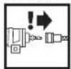
gag g) ais baiu jigu cuiu Jua Lao Log laliojia
Gaaaloo,laaLao jgalejg g aas ctae (gai Laaiao
caLw gao jagw g laeao aiio gao jagw sly kJls g Jauil caleao
juaqao g ycuuus Lggej Aarao jkss uoi jai oaiy
gai jai i ci jie jao aiei jn gao Jiaai lalaeio jao Lgai
9 9 9 9 9 9 9 9 9 9 9 9 9 9 9 9 9 9 9 9 9 9 9 9 9 9 9 9 9 9 9 9 9
6 45 21 JU5
7L 4 L
19 10
19 10
Senior Vice President
Engineering
Dr. Eckerhard Strötgen
Head of Product
Certification

Robert Bosch GmbH, Power Tools Division
D-70745 Leinfelden-Echterdingen
a1jLc:awgLi jgho 0e:ws.0
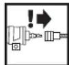
jss aee jn no ggh 45 oioo Juaa aea 0s ciei i
jL 1
Lilgfoiaio jggw oai JIwai zibg wu Lwosolg aui
aJluiai aiai 100w Lao aLjoo
aaiolaiwslgysloosgai gai gai jiljol
yJLg 4 y
g 2g
jolgaiy jie jie jlejLg jg
g aaii 1i jie iil Jla sla 5n si oalw f sol yj
aagg ggljlae
jLJgagog jlaIw,2ggo jguy sIgaw gLoJgJy
oaiw Lwwi gagw g aJg jia yagao 0e
jLg 10000000000000000000000000000000000000000000000
a1g0jLj0jLj0j0i5 g00000000000000000000
cly asiy gog y ool: wos biolj jLg go 1 jy jy j
1j 10g g 100000000000000000000000000000000000000
201
j≤1ocgol
a
e 1
gaww glaoljLwLg

0L:wj10la:wl2j1g
g jw w gjw jw qai jw jai gls lgl s
i 150
gLg2jdo Lg 1. g0 j J.
aaii 1
jg j 10
saiw jao g 10
a<.>
Lg 1000000000000000000000000000000000000000000
Lolol, 4j j
1
2
1g8 3
J 4
5
L 6
w7
wLcJL>J<5g
(aieoojgwo.()gfoailo 9
10
aocowjgsai bii gj
12
45 45 45 45 45 45 45 45 45 45 45 45 45 45 45 45 45 45 45 45 45 45 45 45 45 45 45 45 45 45 45 45 45 45 100000000000000000000000000000000000000000000000000000000000000
golgljolj1j cbiogolaiwlogn
a 1003 1003 a 1003 a 1003 a 1003 a 1003 a 1003 a 1003 a 1003 a 1003 a 1003 a 1003 a 1003 a 1003 a 1003 a 1003 a 1003 a 1003 a 10
a 111111111111111111111111111
g 1 j g 1 j 1 j 1 j 1 j 1 j 1 j 1 j 1 j 1 j 1 j 1 j 1 j 1 j 1 j 1 j 1 j 1 j 1 j 1 j 1 j 1 j 1 j 1 j 1 j 1 j 1 j 1 j 1 j 1 j 1 j 1 j 1 j 1 j 1 j
5u 111 111 111 111 111 111 111 111 111 111 111 111 111 111 111 111 1
1j 1 j 1 j 1 j 1 j 1 j 1 j 1 j 1 j 1 j 1 j 1 j 1 j 1 j 1 j 1 j 1 j 1 j 1 j 1 j 1 j 1 j 1 j 1 j 1 j 1 j 1 j 1 j 1 j 1 j 1 j 1 j 1 j 1 j 1 j
yiei yagc jgsg jolalw pae g, gla jla i j 1j 1j 1j 1j 1j 1j 1j 1j 1j 1j 1j 1j 1j 1j 1j 1j 1j 1j 1j 1j 1j 1j 1j 1j 1j 1j 1j 1j 1j 1j 1j 1j 1j 1j
olcius sio glo cuius as uulu biau yuag sglj j 1 jzj tlebi as uis juiis uuaa aaii jg aiiis jk ljs iueo ng aig oolius ciuus slyocilaoasuiu jyuyu wiyg wicw g uac g uucu
ydyds JgJyds yds yds yds yds yds yds yds yds yds yds yds yds yds yds yds yds yds yds yds yds yds yds yds yds yds yds yds yds yds yds yds yds yds yds yds yds yds yds yds yds yds yds yds yds yds yds yds yds yds yds
#
gaiy jai 150 g aiai 150 150 150
g g s Ls oL e: w s g i g Lg JooJIg
SΔL = 12 dot CD dot CM = 12 × CD × 5
solilwgiclj

Jg 10000000000000000000000000000000000000000000000000000000000
4g 44
Laiu Laiu 150
j 1 j 1 j 1 j 1 j 1 j 1 j 1 j 1 j 1 j 1 j 1 j 1 j 1 j 1 j 1 j 1 j 1 j 1 j 1 j 1 j 1 j 1 j 1 j 1 j 1 j 1 j 1 j 1 j 1 j 1 j 1 j 1 j 1 j 1 j
g j 1 1 1 1 1 1 1 1 1 1 1 1 1 1 1 1 1 1 1 1 1 1 1 1 1 1 1 1 1 1 1 1 1 1 1 1 1 1 1 1 1 1 1 1 1 1 1 1 1 1 000000000000000000000000000000000000000000000000000000000000000000000000000000000000000

L
jglal
g
L 154 123 124 125
gjglg jgi jglglaia glaia glaiaa
jhuws
jLJ-0
gagc gles Jao jaoBj oJyLs gji gj yLoo Joo
Jg 1000000000000000000000000000000000000000000000000000000000000000000
1 1 1 1 1 1 1 1 1 1 1 1 1 1 1 1 1 1 1 1 1 1 1 1 1
golgl
DINISO8573-1 5 5g j gj g j g j g j g j g j g j g j g j g j g j g j g
glg 15 g jis Jjis jilu, g uu wu g 1g 1g 1g 1g 1g 1g 1g 1g 1g 1g 1g 1g 1g 1g 1g 1g 1g 1g 1g 1g 1g 1g 1g 1g 1g 1g 1g 1g 1g 1g 1g 1g 1g 1g
g 1 g a iis Jg a g aaii jy gaaiaa y aaiy
g jogj goo y iu uo aagaae gao aas
Jolil
goljglgagglgagglgagglgagglgagglgagglgagglgagglgagglgagglgagglgagglgagglgagglgagglgagglgagglgagglgagglgagglgagglgagglgagglgagglgagglgagglgagglgagglgagglgagglgagglgagglgagglgag
jolai jai jai jai jai jai jai jai jai jai jai jai jai jai jai jai jai jai jai jai jai jai jai jai jai jai jai jai jai jai jai jai jai jai jai jai jai jai jai jai jai jai jai jai jai jai jai jai jai jai jai
Jl JlJIJI JJI JJI JJI JJI JJI JJI JJI JJI JJI JJI JJI JJI JJI JJI JJI JJI JJI JJI JJI JJI JJI JJI JJI JJI JJI JJI JJI JJI JJI JJI JJI JJI JJI JJI JJI JJI JJI JJI JJI JJI JJI JJI JJI JJI JJI JJI JJI JJI JJI JJI
1 1 1 1 1 1 1 1 1 1 1 1 1 1 1 1 1 1 1 1 1 1 1 1 1 1 1 1 1 1 1 1 1 1 1 1 1 1
a 1 1 1 1 1 1 1 1 1 1 1 1 1 1 1 1 1 1 1 1 1 1 1 1 1 1 1 1 1 1 1 1 1 1 1 1 1 1 1 1 1 1 1 1 1 1 1 1 1 1 0
e 150
0L:wj10la:wl2j1g
g jw w gjw jw qai jw jai gls lgl s i 150 gLg2jdo Lg 1. g0 j J. aaii 1 jg j 10 saiw jao g 10a<.>
Lg 1000000000000000000000000000000000000000000 Lolol, 4j j 1 2 1g8 3 J 4 5 L 6 w7 wLcJL>J<5g (aieoojgwo.()gfoailo 9 10 aocowjgsai bii gj 12 45 45 45 45 45 45 45 45 45 45 45 45 45 45 45 45 45 45 45 45 45 45 45 45 45 45 45 45 45 45 45 45 45 45 100000000000000000000000000000000000000000000000000000000000000 golgljolj1j cbiogolaiwlogn a 1003 1003 a 1003 a 1003 a 1003 a 1003 a 1003 a 1003 a 1003 a 1003 a 1003 a 1003 a 1003 a 1003 a 1003 a 1003 a 1003 a 1003 a 10 a 111111111111111111111111111 g 1 j g 1 j 1 j 1 j 1 j 1 j 1 j 1 j 1 j 1 j 1 j 1 j 1 j 1 j 1 j 1 j 1 j 1 j 1 j 1 j 1 j 1 j 1 j 1 j 1 j 1 j 1 j 1 j 1 j 1 j 1 j 1 j 1 j 1 j 1 j 5u 111 111 111 111 111 111 111 111 111 111 111 111 111 111 111 111 1 1j 1 j 1 j 1 j 1 j 1 j 1 j 1 j 1 j 1 j 1 j 1 j 1 j 1 j 1 j 1 j 1 j 1 j 1 j 1 j 1 j 1 j 1 j 1 j 1 j 1 j 1 j 1 j 1 j 1 j 1 j 1 j 1 j 1 j 1 j yiei yagc jgsg jolalw pae g, gla jla i j 1j 1j 1j 1j 1j 1j 1j 1j 1j 1j 1j 1j 1j 1j 1j 1j 1j 1j 1j 1j 1j 1j 1j 1j 1j 1j 1j 1j 1j 1j 1j 1j 1j 1j olcius sio glo cuius as uulu biau yuag sglj j 1 jzj tlebi as uis juiis uuaa aaii jg aiiis jk ljs iueo ng aig oolius ciuus slyocilaoasuiu jyuyu wiyg wicw g uac g uucu ydyds JgJyds yds yds yds yds yds yds yds yds yds yds yds yds yds yds yds yds yds yds yds yds yds yds yds yds yds yds yds yds yds yds yds yds yds yds yds yds yds yds yds yds yds yds yds yds yds yds yds yds yds yds # gaiy jai 150 g aiai 150 150 150g g s Ls oL e: w s g i g Lg JooJIg
SΔL = 12 dot CD dot CM = 12 × CD × 5 solilwgiclj  Jg 10000000000000000000000000000000000000000000000000000000000 4g 44 Laiu Laiu 150 j 1 j 1 j 1 j 1 j 1 j 1 j 1 j 1 j 1 j 1 j 1 j 1 j 1 j 1 j 1 j 1 j 1 j 1 j 1 j 1 j 1 j 1 j 1 j 1 j 1 j 1 j 1 j 1 j 1 j 1 j 1 j 1 j 1 j 1 j g j 1 1 1 1 1 1 1 1 1 1 1 1 1 1 1 1 1 1 1 1 1 1 1 1 1 1 1 1 1 1 1 1 1 1 1 1 1 1 1 1 1 1 1 1 1 1 1 1 1 1 000000000000000000000000000000000000000000000000000000000000000000000000000000000000000  Ljglal
g
L 154 123 124 125 gjglg jgi jglglaia glaia glaiaa jhuws jLJ-0 gagc gles Jao jaoBj oJyLs gji gj yLoo Joo Jg 1000000000000000000000000000000000000000000000000000000000000000000 1 1 1 1 1 1 1 1 1 1 1 1 1 1 1 1 1 1 1 1 1 1 1 1 1 golgl DINISO8573-1 5 5g j gj g j g j g j g j g j g j g j g j g j g j g j g glg 15 g jis Jjis jilu, g uu wu g 1g 1g 1g 1g 1g 1g 1g 1g 1g 1g 1g 1g 1g 1g 1g 1g 1g 1g 1g 1g 1g 1g 1g 1g 1g 1g 1g 1g 1g 1g 1g 1g 1g 1g g 1 g a iis Jg a g aaii jy gaaiaa y aaiy g jogj goo y iu uo aagaae gao aas Jolil goljglgagglgagglgagglgagglgagglgagglgagglgagglgagglgagglgagglgagglgagglgagglgagglgagglgagglgagglgagglgagglgagglgagglgagglgagglgagglgagglgagglgagglgagglgagglgagglgagglgagglgag jolai jai jai jai jai jai jai jai jai jai jai jai jai jai jai jai jai jai jai jai jai jai jai jai jai jai jai jai jai jai jai jai jai jai jai jai jai jai jai jai jai jai jai jai jai jai jai jai jai jai jai Jl JlJIJI JJI JJI JJI JJI JJI JJI JJI JJI JJI JJI JJI JJI JJI JJI JJI JJI JJI JJI JJI JJI JJI JJI JJI JJI JJI JJI JJI JJI JJI JJI JJI JJI JJI JJI JJI JJI JJI JJI JJI JJI JJI JJI JJI JJI JJI JJI JJI JJI JJI JJI 1 1 1 1 1 1 1 1 1 1 1 1 1 1 1 1 1 1 1 1 1 1 1 1 1 1 1 1 1 1 1 1 1 1 1 1 1 1 a 1 1 1 1 1 1 1 1 1 1 1 1 1 1 1 1 1 1 1 1 1 1 1 1 1 1 1 1 1 1 1 1 1 1 1 1 1 1 1 1 1 1 1 1 1 1 1 1 1 1 0 e 150


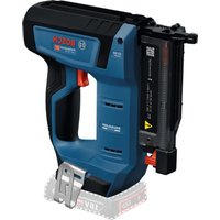
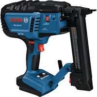
- GCN 45-15 Professional
- General Safety Rules for Pneumatic Tools
- 4WARNING
- Work area safety
- Pneumatic tool safety
- Personal safety
- Pneumatic tool use and care
- Service
- SafetyWarnings for Compressed-air Nailers/Staplers
- Wear safety goggles.
- Do not work on ladders or scaffolds when the actuation system "Contact actuation" is set. In particular, do not move from one fastening location to another, close boxes or enclosures, or fasten transport-securing fix
- Disconnect the air supply, when the fastener is jammed in the pneumatic tool. When the pneumatic tool is still connected to the power supply, it can accidentally be actuated when removing a jammed fastener.
- | English
- Product Description and Specifications
- Intended Use
- Product Features
- Noise/Vibration Information
- Technical Data
- Declaration of Conformity C
- Connecting the Air Supply
- Connecting the Air Supply to the Pneumatic Tool (see figure A)
- Changing the Trigger (see figures B1-B2)
- Symbol Trigger Actuation system
- Removing the Trigger
- Mounting the Trigger
- Loading the Magazine (see figures C1-C3)
- Operation
- Actuation systems
- | English
- Starting Operation
- Working with Single Actuation (see figure D)
- Working with Contact Actuation (see figure E)
- Working Advice
- Emptying the Magazine
- Adjusting the Depth Stop (see figure F)
- Nails are not driven in deep enough:
- Clearing Jams (see figure G)
- Adjusting the Spacer Block (seefigure H)
- Transport and Storage
- Maintenance and Service
- Maintenance and Cleaning
- Maintenance Schedule
- Lubricating the Pneumatic Tool (see figure I)
- Removing Debris/Contamination from Tar (see figure J)
- | English
- Accessories
- After-sales Service and Customer Assistance
- www.bosch-pt.com
- Great Britain
- Ireland
- Australia, New Zealand and Pacific Islands
- Republic of South Africa
- Customer service
- Gauteng - BSC Service Centre
- KZN - BSC Service Centre
- Western Cape - BSC Service Centre
- Bosch Headquarters
- | Français
- Disposal
- Français
- Montagem
- Bortskaffelse
- Avfallshantering
- Tasfiye
- Montáž
- Pripojeni na zdroj vzduchu
- Vymena spousté (viz obr. B1-B2)
- Be30nachOCTb THeBMaTHueCkHX HnCTpyMeHToB
- Be30TnachOCTb AIODeE
- TuatalebHoe 06xoxkdeHHe CTHEBMOHCTpyMeHTAMN HXTIpaBbHoe npMmeHHe
- CepBnC
- Yka3aHnI NO TexHKe 6e30NaCHOCTH AAR THEBMATNueCkHX CkO6o-N rB03e3a6NBbIX HHCTpymENTOB
- Pycckn
- OtncaHne ppoAkykTa n ycAyr
- TIPMHeHHe ITO Ha3HaueHHIO
- H306paxeHHbIe coCTaBhbIe qactn
- AaHbIe TIO WMy H Bn6paunu
- OeBaIte HauHHNK!
- 3aBAAeHHe 0 COOTBeCTBHN
- CE
- IPhcoeAHHeHHe HHTaHHcKaTbIM BO3dYOM KTHHEBMHOHCTpyMeHTy (cm.phc.A)
- 3aMeHa cTnyckoBOrO KpUQKa (cM. pHc. B1-B2)
- AemOHax CTyckOBOro KpOuKa
- Mohtax CnyckOBoro KpOuKa
- 3aTOnAHeHneMaRa3nHa (cm.pnc.C1-C3)
- >ICnToa3yTe ToaKo OPHTHAaHbHbeI TPHaadEaeXhoCTB Bosch (cM.
- - OAnopa30BbI cTnyck C bIaepKkoN
- KoHTaKTbIcNyck
- Bkluoyenne
- Pa60Ta cOaHopa3OBbIM CTYcKOM (cM.pHC.D)
- Pa60Ta C KOHTAKTHBIM CTYCKOM (CM.PHC.E)
- Yka3aHnI IO TpIMHeHnIO
- OToPoxKHeHMeMara3Ha
- Hactpoika orpaunuHTeA rAy6HHbI (cm. pnc.F)
- Tb03An 3a6hBAOTcH Ae DOCTaTOuHO TAY60ko:
- YdAeHHe 3actpBwHx rBaO3eH (cm. pnc. G)
- Hactpoika pactophoro 3aementa (cm.phc.H)
- TpaHCTOPTNPOBka H xpaHeHMe
- Texo6cayxmbaHne n cepBnC
- Texo6cayxHBHne H ouhctka
- Cma3Ka THeBMOHcTpyMeHTa (cm. phc.1)
- IIaan IIOAdepKHN B6eynpeHOM TEXHHueckOM COCTOHHN
- Bka3iBKn 3 TexHkN 6e3NeKn DAA THeBMaTHuHNx CkO6o-i QBHX03a6NBHNx NiCTOAEtIB
- Onnc npoAkyTiy i nocayr
- Pn3naueHH
- 3o6paXeHi KOMTOHeHTN
- Texhi Dahi
- CtoopoxHeHHMaar3Hha
- HactpoOBaHHo6mexyBaHa rAaBHHn(AaM.A.F)
- Româna
- Eliminare
- Eliminati ecologic lubrifianti si detergentii. Respectati prevederile tegale.
- CbxpaaBaiyeka3aHnra 3a6e0taacha pa6ota rpnKAnBO.
- Be30nachOCTHa pa6oTHOTMOACTO
- Be30nachapa6oTa CTHEBMaTHHHHhCTpymEnT
- PmKANBO OTHOWeHHe KbM H IOA3BaHe Ha TTHEBMaTHHHHCTpyMeHTH
- CepBn3
- Yka3aHn 3a6e3oNa cha pa6ota c THeBMaTHnMaunnn 3a 3a6nBahe
- Pa6oTeTe C npEa3Hn OuaA.
- OtticaHHe Ha IpoAkyTa N Bb3MOxHOCHTe My
- IpeHa3NaueHne Ha HnCTpyMeHa
- H306pa3eHH eAeMeHTN
- Hhopmaa3a H3buaBan yuM Hb6paau
- Pa6oTeC wymo3aayuImteH!
- Aekapaua 3a cbotbetCTBne C
- BkAIOUBaHe Na CnCTeMaTa 3a CbCTeH Bb3dYX KbM THeBMaTHNHa HnCTpyMeNT (BmTe dHr. A)
- CmHaHa cnTycbuHTe (BnXTe nHyprn B1-B2)
- AemOHtnpaHe Ha cnYcBx
- MOnThpaHa cTcybK
- 3apexdaheHa mara3nHa (BHXTe fHpyn C1-C3)
- IpeHdAITpOMeHrTeHaCTPOHN,da3aMeHrTe
- PnTOCTaBAHHe HAneHTaC TINPOHN BHIMMABaHTeTeAeHNTe
- Pa6ota
- CHCTeMH Ha H3CTpeAbaHe
- -EDHHHNO H3CTpeBAHe Cde6AOKnpaHe Ha PpeDn3HTeA
- -KoHTaKTHO H3CTpeABAHe
- BkAIOUBAHc
- Pa6ota c eHHHn H3CTpean (BHXTE phr.D)
- Pa6ota c KONTAKTHO 3CTpeBAbahe (BHXTe H.E)
- Yka3aHnHa 3pa6oTa
- HnpaBaHeHa mara3HHa
- HaTpoBaHe Ha dba6oHHHnOrpaHHHTe (BHXTe pHrypFaF)
- N3BaXdaHe Ha 3aKAnHeH KpTeXeH eAeMeHT (BnKTe pHrpya G)
- HactpoBahe Ha nctanuHepa (BHXte pHrypa H)
- TpaHcTIOPTIpaHEn CbXpaHraBaHe
- PoaBpKaHe n cepBn3
- IpoAdbpxkaneHIOUCHTBaHe
- Cma3BaHe Ha THEBMaTHMnHm HnCTpyMeHT (BHXTe pHr.1)
- OTcpaHbBAHe Ha 3aMbpCBAHHoT cMOa(BHXTe Hr.J)
- Taan3aTexHuecko06cayxbahe
- Montaža
- ppa. 11. nuoy
- bglal 1gbl jwll 8j 2j 2j 2j
- #
- 1
- b jai 1jai jai jai jai jai
- A
- lalb = 0
- (C1-C3 gLw 4 w
- j≤1ocgol a e 1 gaww glaoljLwLg  0L:wj10la:wl2j1g
- a<.>
- g g s Ls oL e: w s g i g Lg JooJIg
- jglal
- g
Brand : BOSCH
Model : GCN 4515 Professional
Category : Stapler