ART 26 Easytrim Accu - Hedge trimmers BOSCH - Free user manual and instructions
Find the device manual for free ART 26 Easytrim Accu BOSCH in PDF.
User questions about ART 26 Easytrim Accu BOSCH
0 question about this device. Answer the ones you know or ask your own.
Ask a new question about this device
Download the instructions for your Hedge trimmers in PDF format for free! Find your manual ART 26 Easytrim Accu - BOSCH and take your electronic device back in hand. On this page are published all the documents necessary for the use of your device. ART 26 Easytrim Accu by BOSCH.
USER MANUAL ART 26 Easytrim Accu BOSCH
Operating Instructions
natural_image
3D rendering of a Bosch handheld vacuum cleaner with handle and spout (no text or symbols visible)


natural_image
Line drawing of a pair of safety goggles (no text or symbols)F 016 800 178
24x

F 016 800 177
(ART 23/2300 EASYTRIM ACCU)
F 016 800 183
(ART 26/2600 EASYTRIM ACCU)


text_image
Safety warning diagram showing hazard and 360° angle with incorrect detection
14
text_image
1 2 3 4 5 6 7 89
text_image
10 11 12 134 • F016 L70 457 • 06.12
text_image
A 4 5 CLICK!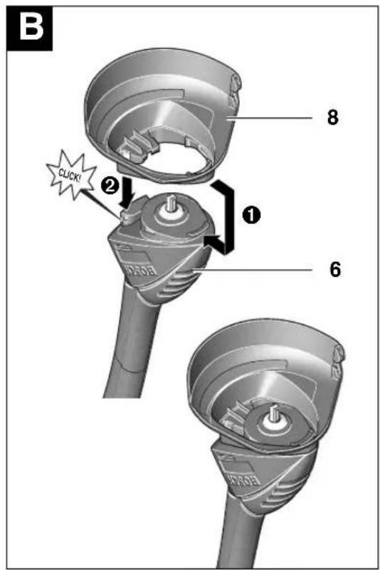
text_image
B 8 ② 1 6 EVO50 EVO50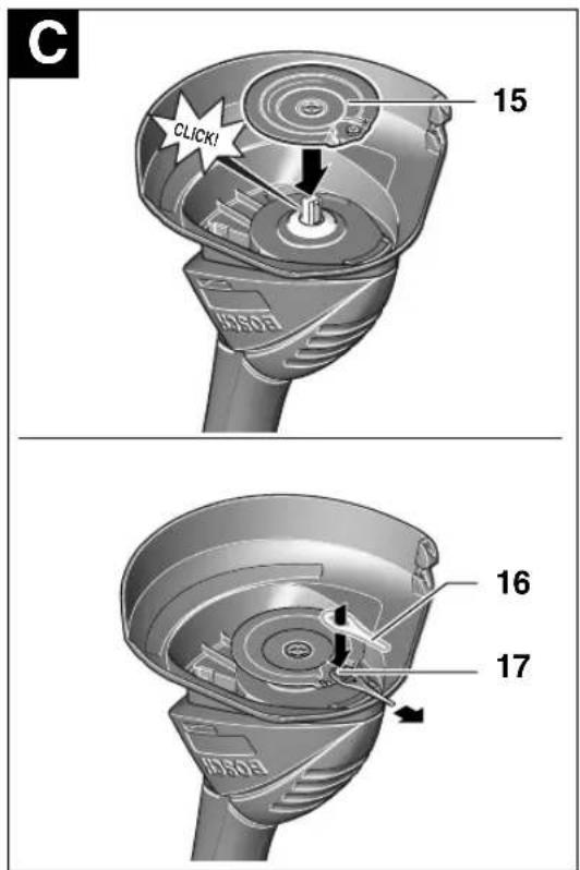
text_image
C 15 CLICK! 16 17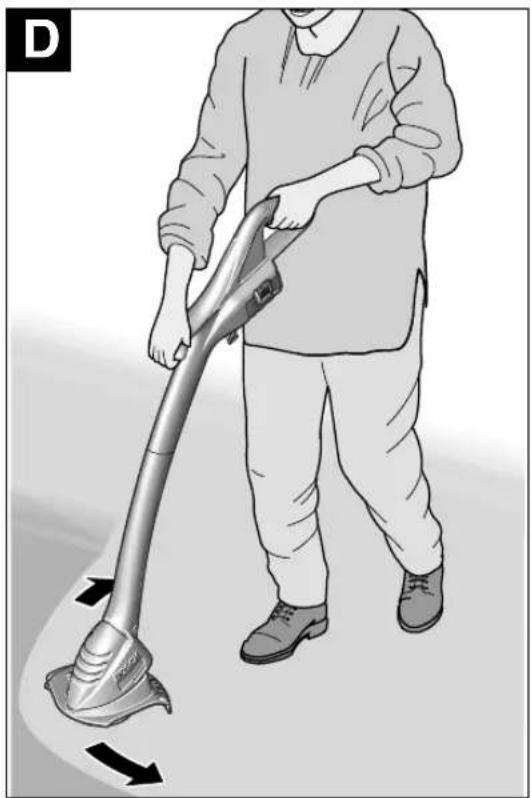
natural_image
Illustration of a person using a hair anti-sprayer cleaning tool, with arrows indicating direction (no text or symbols)5·F016 L70 457·06.12

Sicherheitshinweise
text_image
Safety warning diagram showing a device with warning symbol, 360° angle, and no visible text or labelsSenior Vice President Head of Product
Engineering Certification
ppa. Amanu i.v. Moyen
Robert Bosch GmbH, Power Tools Division
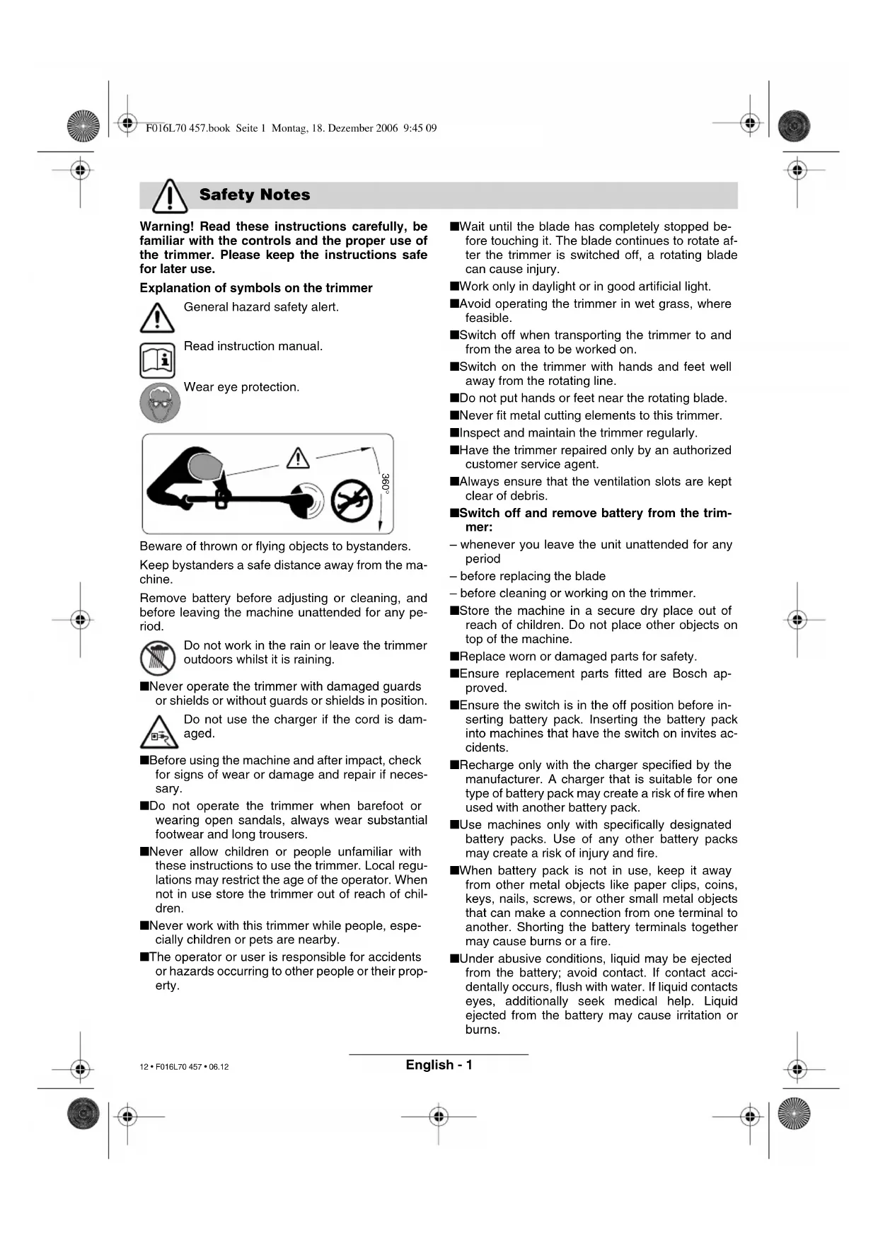
Warning! Read these instructions carefully, be familiar with the controls and the proper use of the trimmer. Please keep the instructions safe for later use.
Explanation of symbols on the trimmer

General hazard safety alert.

Read instruction manual.
Wear eye protection.


text_image
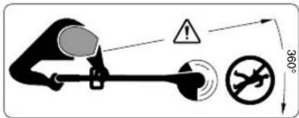
360°Beware of thrown or flying objects to bystanders.
Keep bystanders a safe distance away from the machine.
Remove battery before adjusting or cleaning, and before leaving the machine unattended for any period.

Do not work in the rain or leave the trimmer outdoors whilst it is raining.
■Never operate the trimmer with damaged guards or shields or without guards or shields in position.

Do not use the charger if the cord is damaged.
■Before using the machine and after impact, check for signs of wear or damage and repair if necessary.
■Do not operate the trimmer when barefoot or wearing open sandals, always wear substantial footwear and long trousers.
■Never allow children or people unfamiliar with these instructions to use the trimmer. Local regulations may restrict the age of the operator. When not in use store the trimmer out of reach of children.
■Never work with this trimmer while people, especially children or pets are nearby.
■The operator or user is responsible for accidents or hazards occurring to other people or their property.
■Wait until the blade has completely stopped before touching it. The blade continues to rotate after the trimmer is switched off, a rotating blade can cause injury.
■Work only in daylight or in good artificial light.
■Avoid operating the trimmer in wet grass, where feasible.
■Switch off when transporting the trimmer to and from the area to be worked on.
■Switch on the trimmer with hands and feet well away from the rotating line.
■Do not put hands or feet near the rotating blade.
■Never fit metal cutting elements to this trimmer.
■Inspect and maintain the trimmer regularly.
■Have the trimmer repaired only by an authorized customer service agent.
■Always ensure that the ventilation slots are kept clear of debris.
■Switch off and remove battery from the trim-mer:
- whenever you leave the unit unattended for any period
– before replacing the blade
– before cleaning or working on the trimmer.
■Store the machine in a secure dry place out of reach of children. Do not place other objects on top of the machine.
■Replace worn or damaged parts for safety.
■Ensure replacement parts fitted are Bosch approved.
■Ensure the switch is in the off position before inserting battery pack. Inserting the battery pack into machines that have the switch on invites accidents.
■Recharge only with the charger specified by the manufacturer. A charger that is suitable for one type of battery pack may create a risk of fire when used with another battery pack.
■Use machines only with specifically designated battery packs. Use of any other battery packs may create a risk of injury and fire.
■When battery pack is not in use, keep it away from other metal objects like paper clips, coins, keys, nails, screws, or other small metal objects that can make a connection from one terminal to another. Shorting the battery terminals together may cause burns or a fire.
■Under abusive conditions, liquid may be ejected from the battery; avoid contact. If contact accidentally occurs, flush with water. If liquid contacts eyes, additionally seek medical help. Liquid ejected from the battery may cause irritation or burns.
Product Specification
| Trimmer ART 23 EASYTRIM ACCU/ ART 2300 EASYTRIM ACCU | ART 26 EASYTRIM ACCU/ ART 2600 EASYTRIM ACCU | ||
| Part number (typ) 3 600 H78 H.. 3 600 H78 J.. | |||
| No-load speed [rpm] 9 500 9 000 | |||
| Cutting circle [cm] 23 26 | |||
| Weight (without optional extras) [kg] 1.9 2.0 | |||
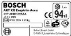
| Serial Number See serial No 14 (rating plate) on machine. | |||
| Battery type NiMH | NiMH | ||
| Battery order number | 2 607 335 699 | 2 607 335 699 | |
| Battery Voltage | [V] | 14.4 | 14.4 |
| Battery rating | [Ah] | 1.5 1.5 | |
| Charging time (empty battery) | [h] | 3 - 5* | 3 - 5* |
| Battery charger | AL 1404 | AL 1404 | |
| Order number | 2 607 225 .. | 2 607 225 .. | |
| Charging current | [A] | 0.4 0.4 | |
| Allowable charging temperature range | [°C] | 0-45 | 0-45 |
*Charging time based on a battery charger input voltage of 230 V.
Intended Use
The product is intended for the cutting of grass and weeds under bushes, as well as on slopes and edges that can not be reached with the lawn mower. Intended Use is related to operation within 0 °C and 40 °C ambient temperature.
Introduction
This manual gives instructions on the correct assembly and safe use of your machine. It is important that you read these instructions carefully.
Delivered Items
Carefully remove the machine from its packaging and check that you have all the following items:
- Trimmer
- Cutting guard
- Cutting disc
- Blades
- Battery charger
- Operating instructions
When parts are missing or damaged, please contact your dealer.
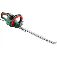
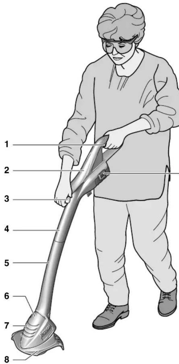
Operating Controls
1 On/Off switch
2 Handle
3 Guide handle
4 Shaft, upper
5 Shaft, lower
6 Trimmer head
7 Ventilation slots
8 Cutting guard
9 Battery
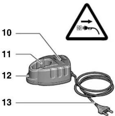
10 Battery charger
11 Chraging compartment
12 LED indicator
13 Mains plug**
14 Serial No
**Country specific
Not all of the accessories illustrated or described are included as standard delivery.

For Your Safety
Warning! Switch off, remove battery from machine before adjusting or cleaning.
The blade continues to rotate for a few seconds after the trimmer is switched off.
Caution – do not touch rotating blade.
Charging Procedure
The charging procedure starts as soon as the mains plug is plugged into the socket and the battery 9 is inserted into the charging compartment 11.
The green LED 12 is not a charge control indicator! When the green LED is lit, it indicates that a charging current flows.
After the end of the charging process (approx. 3 h–5 h), pull the mains plug of the battery charger from the socket and remove the battery.
The battery should not be charged for longer than 5.5 hours.
A temperature increase of the battery indicates that it is fully charged.
Charging Advice
With continuous or several repetitive charging cycles without interruption, the charger can warm up. This is not harmful and does not indicate a technical defect of the unit.
A battery that is new or has not been used for a longer period does not develop its full capacity until after approximately 5 charging/discharging cycles. Leave such batteries in the charging compartment until they have clearly warmed up.
A significantly reduced working period after charging indicates that the batteries are used and must be replaced.
Assembly

Do not connect the battery before product is completely assembled.
Ensure product is assemble in the following order:

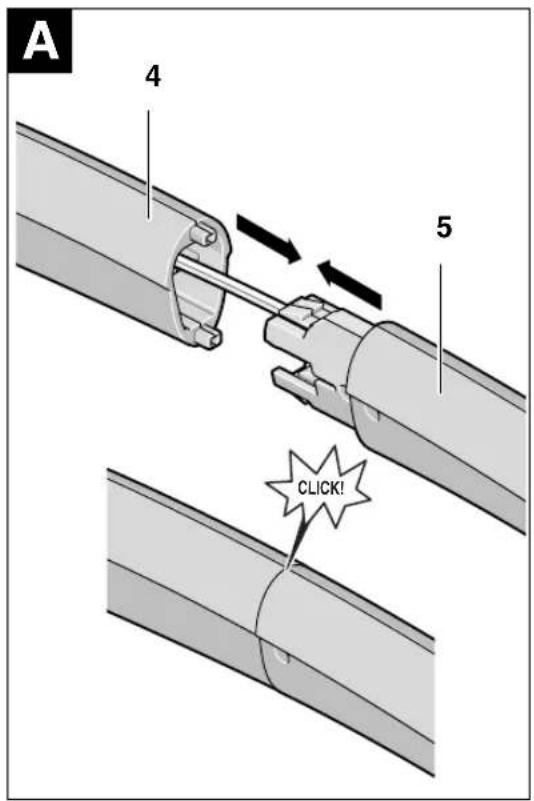
Assemble trimmer shaft
Push the upper shaft 4 and lower shaft 5 together until a click can be heard.
Note: Once the upper and lower shaft is assembled it can not be disassembled.
Ensure internal cable is not trapped or twisted.
B Mounting the Cutting Guard
Place the cutting guard 8 on the trimmer head 6.
① Hook the guard onto trimmer head and push until secure fitting.
② Push rear of guard until secure (click).
C Fitting Cutting Disc/Fitting Blade
Press cutting disc 15 onto drive adaptor as shown (click).
Fit the blade, place the blade 16 over the pivot 17 and pull outwards until it snaps into place.
Cutting and Edging

Remove stones, loose pieces of wood and other objects from the cutting area.
The blade continues to rotate for a few seconds after the trimmer is switched off. Allow the motor/blade to stop rotating before switching "on" again.
Do not rapidly switch off and on.
Switching On and Off
Press switch 1 and hold depressed. Release switch 1 for switching off.
D Cutting Grass
Move the trimmer left and right, keeping it well away from the body.
The trimmer can efficiently cut grass up to a height of 15 cm. Cut taller grass in stages.
Cutting Around Trees and Bushes
Carefully cut around trees and bushes so that they do not come into contact with the cutting line.
Plants can die if you damage the bark.
Battery duration
Battery duration is dependent on the working conditions:
light conditions:
up to 500 metres
medium conditions:
up to 300 metres
tough conditions:
up to 50 metres
Maintenance

Before any work on the machine itself, remove battery from machine.
Note: To ensure long and reliable service, carry out the following maintenance regularly.
Regularly check for obvious defects such as loose fixings, and worn or damaged components.
Check that covers and guards are undamaged and correctly fitted. Carry out necessary maintenance or repairs before using.
If the trimmer should happen to fail despite the care taken in manufacture and testing, repair should be carried out by an authorized customer service agent for Bosch garden products.
For all correspondence and spare parts orders, always include the 10-digit part number (TYP) from the nameplate of the machine!

Blade Maintenance

Before any work on the machine itself, remove battery from machine.
To remove the worn blade 16 push in direction of the arrow until it snaps off the pivot 17.
Clean the pivot 17 of any residual plastic/debris with a sharp knife.
To refit the new blade 16 place the eyelet over the pivot 17 and pull outwards until it snaps into place.
Note: Only use Bosch replacement blades. They have been developed specially for improved cutting performance. The use of other cutter blades will lead to a deterioration in performance and possible damage to the product.
After Trimming/Storage

Stop and remove battery from product. Ensure battery is removed before storage.
Clean the exterior of the machine thoroughly using a soft brush and cloth. Do not use water, solvents or polishes. Remove all grass and debris, especially from the ventilation slots 7.
Turn the machine on its side and clean the cutting guard 8 inside. If grass cuttings are compacted, remove with a wooden or plastic implement.
Battery should be stored between 0 – 45 °C; incorrect storage could result in the battery being damaged.
Fault Finding
The following table gives checks and actions that you can perform if your machine does not operate correctly. If these do not identify/remedy the problem, contact your service agent.
Warning: Switch off and remove battery before investigating fault.
| Symptom Possible Cause | Remedy | |
| Can not fit Guard over cutting disc | Incorrect assembly Remove cutting disc | and fit guard, see also Product assembly |
| Machine fails to operate Battery | discharged Recharge battery, see | also Charging advice |
| Machine functions intermittently | Internal wiring defectiveOn/Off switch defective | Contact Service AgentContact Service Agent |
| Excessive vibration/ noise | Machine faultBlade broken | Contact Service AgentReplace blade |
| Cutting time low on one battery charge | Battery not used for long period or initial usageGrass too highBattery worn out | Fully charge battery, see also charging adviceCut in stagesReplace the battery |
| Blade will not move Battery | dischargedMachine fault | Recharge battery, see also Charging adviceContact Service Agent |
| Machine is not cutting Blade | brokenBattery not fully chargedGrass entangled around cutting disc | Replace bladeRecharge battery, see also Charging adviceRemove grass |
| No charging procedure possible due to defective battery | The contacts of the battery are contaminatedThe battery is defective, due to a disconnection in the battery (individual cells) | Clean the contacts (e. g. by inserting and removing the battery several times) or replace the battery, as requiredReplace the battery |
| The LED indicator 12 does not light up after plugging the mains plug into the socket and inserting the battery into the charging compartment 11 | The charger plug is not inserted (properly)Socket, cable or charger are defective | Insert the plug (fully) into the socketCheck the mains voltage and if necessary, have the battery charger checked by an authorized customer service station for Bosch garden tools |
Disposal
Product, accessories and packaging should be sorted for environmentally-friendly recycling.
Only for EC countries:
Do not dispose of the product into household waste!
According to the European Directive 2002/96/EC on waste electrical and electronic equipment and its incorporation into national law, products that
are no longer suitable for use must be separately collected and sent for recovery in an environmentally-friendly manner.
Service
Exploded views and information on spare parts can be found under:
www.bosch-pt.com
Great Britain
Robert Bosch Ltd. (B.S.C.)
P.O. Box 98
Broadwater Park
North Orbital Road
Denham-Uxbridge
Middlesex UB 9 5HJ
Service....+44 (0) 18 95 / 83 87 82
Fax Service +44 (0) 18 95 / 83 87 89
©Advice line....+44 (0) 18 95 / 83 87 91
Fax Advice....+44 (0) 18 95 / 83 87 93
Ireland
Beaver Distribution Ltd.
Greenhills Road
Tallaght-Dublin 24
Service....+353 (0)1 / 45 15 211
Fax +353 (0)1 / 45 17 127
Malaysia
Robert Bosch (SEA.) Pte. Ltd.
No. 8a, Jalan 13/6
Selangor Darul Ehsan
Petaling Jaya 46200
Malaysia
① +60 3 79 58 30 00
Fax (EW Dept.) +60 3 79 58 38 38
www.bosch.com.sg
Australia
Robert Bosch Australia Ltd.
RBAU/SPT2
1555 Centre Road
P.O. Box 66 Clayton
3168 Clayton/Victoria
+61 (0)1 / 800 804 777
Fax +61 (0)1 / 800 819 520
www.bosch.com.au
E-Mail: CustomerSupportSPT@au.bosch.com
New Zealand
Robert Bosch Limited
14-16 Constellation Drive
Mairangi Bay
Auckland
New Zealand
Declaration of Conformity
Measured values determined according to 2000/14/EC (1.60 m height, 1.0 m distance away) and EN 28 662.
Typically the A-weighted noise level of the product is: sound pressure level 72 dB (A); sound power level 88 dB (A).
The typical hand/arm vibration is below 2.5 m/s ^4 .
We declare under our sole responsibility that this product is in conformity with the following standards or standardization documents: EN 786, EN 60 335 according to the provisions of the directives 89/336/EEC, 98/37/EC, 2000/14/EC.
2000/14/EC: The guaranteed sound power level L_WA is lower than 94 dB (A). Conformity assessment procedure according to Annex VI.
Notified body: SRL, Sudbury England
Notified body identifications number: 1088
Leinfelden, 01.06.2006.
Dr. Egbert Schneider Dr. Eckerhard Strötgen
Senior Vice President Head of Product
Engineering Certification
ppa. A##ka i.v. Mo#gen
Robert Bosch GmbH, Power Tools Division
Subject to change without notice

text_image
Safety warning diagram showing hazard and safety symbol with 360° angle indicator© Monter le plateau/la lame
Robert Bosch France S.A.S.
Service Après-vente/Outillage
Senior Vice President Head of Product
Engineering Certification
ppa. Hamka i.v. Mozyen
Robert Bosch GmbH, Power Tools Division
Senior Vice President Head of Product
Engineering Certification
ppa. Mauca i.v. Nuoyen
Robert Bosch GmbH, Power Tools Division
text_image
Safety warning diagram showing a person using a device with warning symbols and a 360° angle indicator.Senior Vice President Head of Product
Engineering Certification
ppa. A##u i.v. N##yen
Robert Bosch GmbH, Power Tools Division
text_image
Safety warning diagram showing a device with warning symbol, 360° angle, and no visible text or labelsSenior Vice President Head of Product
Engineering Certification
ppa. Aneka i.v. Moyen
Robert Bosch GmbH, Power Tools Division
Senior Vice President Head of Product
Engineering Certification
ppa. Alwata i.v. Mozyu
Robert Bosch GmbH, Power Tools Division
After trimming/opbevaring

Senior Vice President Head of Product
Engineering Certification
ppa. Amanu i.v. Nguyen
Robert Bosch GmbH, Power Tools Division
text_image
Safety warning diagram showing a device with warning symbol, 360° angle, and no visible text or labelsDr. Egbert Schneider Dr. Eckerhard Strötgen Senior Vice President Head of Product Engineering Certification
ppa. A##ca i.v. Mo#gen
Robert Bosch GmbH, Power Tools Division
Senior Vice President Head of Product
Engineering Certification
ppa. Mauca i.v. Nuoyen
Robert Bosch GmbH, Power Tools Division
text_image
Safety warning diagram showing a device with warning symbol, 360° angle, and no visible text or labelsSenior Vice President Head of Product
Engineering Certification
ppa. Ashan i.v. Mozyen
Robert Bosch GmbH, Power Tools Division
Dr. Egbert Schneider Dr. Eckerhard Strötgen Senior Vice President Head of Product Engineering Certification
ppa. Amata i.v. Noyen
Robert Bosch GmbH, Power Tools Division
Dr. Egbert Schneider Dr. Eckerhard Strötgen Senior Vice President Head of Product Engineering Certification
ppa. A##u i.v. Mo#en
Robert Bosch GmbH, Power Tools Division
Dr. Egbert Schneider Dr. Eckerhard Strötgen Senior Vice President Head of Product Engineering Certification
ppa. Jauuca i.v. Nuoyen
Robert Bosch GmbH, Power Tools Division
Senior Vice President Head of Product
Engineering Certification
ppa. Amanu i.v. Moyen
Robert Bosch GmbH, Power Tools Division
Změny vyhrazeny

Bezpečnostné pokyny
Dr. Egbert Schneider Dr. Eckerhard Strötgen Senior Vice President Head of Product Engineering Certification
ppa. A##ca i.v. Mo#gen
Robert Bosch GmbH, Power Tools Division
text_image
Safety warning diagram showing hazard symbol, safety warning sign, and safety symbol with 360° angle annotationDr. Egbert Schneider Dr. Eckerhard Strötgen Senior Vice President Head of Product Engineering Certification
ppa. A##u i.v. Mo#en
Robert Bosch GmbH, Power Tools Division
text_image
Safety warning diagram showing a device with warning symbol, 360° angle, and no visible text or labelsDr. Egbert Schneider Dr. Eckerhard Strötgen Senior Vice President Head of Product Engineering Certification
ppa. Jauuca i.v. Nuoyen
Robert Bosch GmbH, Power Tools Division
Dr. Egbert Schneider Dr. Eckerhard Strötgen Senior Vice President Head of Product Engineering Certification
ppa. A##u i.v. M#y##
Robert Bosch GmbH, Power Tools Division
Можливі зміни

119·F016L70 457·06.12
Українська - 6


text_image
Safety warning diagram showing a device with warning symbol, safety warning sign, and 360mm height dimensionBosch Service Center
România
Str. Horia Măcelariu 30 – 34, sector 1, București
Dr. Egbert Schneider Dr. Eckerhard Strötgen Senior Vice President Head of Product Engineering Certification
ppa. deuca i.v. nuoyen
Robert Bosch GmbH, Power Tools Division
natural_image
Three vertical panels showing grass or reeds in different orientations (no text or symbols)Dr. Egbert Schneider Dr. Eckerhard Strötgen Senior Vice President Head of Product Engineering Certification
ppa. Amata i.v. Moyen
Robert Bosch GmbH, Power Tools Division
Senior Vice President Head of Product
Engineering Certification
ppa. Jauca i.v. Nuoyen
Robert Bosch GmbH, Power Tools Division
text_image
Safety warning diagram showing hazard, safety symbol, and 360° angle indicatorSenior Vice President Head of Product
Engineering Certification

i.v. Puoyen
Robert Bosch GmbH, Power Tools Division
Pridržujemo si pravico do sprememb

143·F016L70 457·06.12
Slovensko - 6


Upute za siguran rad
text_image
Safety warning diagram showing hazard and 360° angle with incorrect detectionPazite da osobe koje se nalaze oko uređaja ne ozlijede odbačena strana tijela.
Treba održavati siguran razmak do osoba koje se nalaze blizu uređaja.
Izvadite aku-bateriju prije nego što ćete uredaj čistiti, podešavati ili na kratko ostaviti bez nadzora.

Senior Vice President Head of Product
Engineering Certification
ppa. A##u i.v. N##yen
Robert Bosch GmbH, Power Tools Division
text_image
Safety warning diagram showing a person using a device with warning symbols and a 360° angle indicator.Senior Vice President Head of Product
Engineering Certification
ppa. Jauuca i.v. Moyen
Robert Bosch GmbH, Power Tools Division
natural_image
Three identical black grass or reeds swaying in a row, with no text or symbols present.Dr. Egbert Schneider Dr. Eckerhard Strötgen Senior Vice President Head of Product Engineering Certification
ppa. Jhaka i.v. Nudgen
Robert Bosch GmbH, Power Tools Division
Senior Vice President Head of Product
Engineering Certification
ppa. A##u i.v. N##yen
Robert Bosch GmbH, Power Tools Division
Power Tools Division
70745 Leinfelden-Echterdingen
www.bosch-pt.com
F016 L70 457 (06.12) O / 168