
PAM 0540 - Air Conditioning BOSCH - Free user manual and instructions
Find the device manual for free PAM 0540 BOSCH in PDF.
| Product type | Monoblock mobile air conditioner |
| Brand | Bosch |
| Model | PAM 0540 |
| Dimensions (approx.) | 70 x 40 x 60 cm (L x D x H) |
| Weight (approx.) | 25 kg |
| Power supply | 220-240 V ~ 50 Hz |
| Recommended fuse | 10 A slow-blow |
| Maximum exhaust hose length | 140 cm |
| Main functions | Air conditioning (cooling), dehumidification, air purification |
| Air conditioning modes | Silent, high, turbo |
| Adjustable thermostat | Yes (range 20-30 °C) |
| Basic filter | Washable with running water (do not put in dishwasher) |
| Purifier filter | Yes, replaceable (ref. PAZ10000 or PAZ11001) |
| Condensate water tank | Manual draining via plug and drain hose |
| Supplied accessories | Air exhaust hose, diffuser, window seal, purifier filter |
| Options (not supplied) | Window/balcony slider, wall penetration |
| Cleaning | Soft cloth with warm water and mild detergent |
| Safety instructions | Do not cover air inlets/outlets; minimum distance 20 cm from surfaces; wait 3 min before restarting |
| Use | Domestic and commercial (offices of similar size) |
| Off-season storage | Fold the air exhaust hose to the back of the appliance |
Frequently Asked Questions - PAM 0540 BOSCH
User questions about PAM 0540 BOSCH
0 question about this device. Answer the ones you know or ask your own.
Ask a new question about this device
Download the instructions for your Air Conditioning in PDF format for free! Find your manual PAM 0540 - BOSCH and take your electronic device back in hand. On this page are published all the documents necessary for the use of your device. PAM 0540 by BOSCH.
USER MANUAL PAM 0540 BOSCH
natural_image
Black-and-white close-up of glossy leaves with water droplets, no text or symbols visible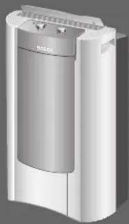
natural_image
3D rendering of a Bosch air purifier unit (no text or symbols visible)PAM0520 PAM0540 PAM0530
natural_image
Symbol of a trash bin with crossed lines indicating no waste or discharge, and a black rectangle below (no text or labels)natural_image
3D diagram of a kitchen appliance with a handle and arrow, labeled Abb. 1 (no text or symbols on the main subject)natural_image
Illustration of a kitchen appliance pouring milk into a bucket on tiled floor (no text or symbols)natural_image
3D diagram of a mechanical component with threaded end and base, no text or symbols presentnatural_image
Diagram of a wall-mounted hose assembly with a handle, showing structural components and a label Abb 13 (no text or symbols on the diagram itself)natural_image
Diagram of a door with an arrow pointing to the left side, showing structural details (no text or symbols)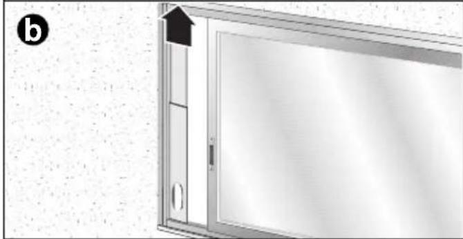
natural_image
Exterior view of a door with an arrow pointing to the top panel (no text or symbols visible)
natural_image
Exterior view of a modern office building (no signage)Festinstallation
natural_image
Illustration of a kitchen sink pouring liquid into a bucket on tiled floor, labeled 'Abb. 21' (no text or symbols on main subject)natural_image
3D rendered mechanical component with threaded spring and base plate, labeled Fig. 22 (no text or symbols on the object itself)natural_image
Close-up of a circular mechanical knob with directional arrows and symbols (no readable text or labels)Achtung!
natural_image
3D rendered knob with leaf and snowflake symbols, no text or numbers presentnatural_image
3D rendered mechanical component with two circular ports and a lid, labeled Abb. 26 (no text or symbols on the main subject)natural_image
3D rendered knob with directional arrows and snowflake symbols, labeled Abb. 27 (no text or numbers on the knob itself)natural_image
Technical diagram of a mechanical assembly with an inset magnified view showing detail (no text or symbols present)natural_image
Diagram of a mechanical component with a curved arrow indicating rotation or force (no text or symbols)Fig. 31
natural_image
3D rendering of a BO2 air duct system with attached tubing, labeled Abb. 33 (no text or symbols on the device itself)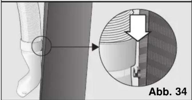
natural_image
Medical illustration showing a foot with a circular marking and a magnified view of a mechanical component (no text or symbols)Environmental protection
Recommendations for the disposal of packaging 20
Recommendations for the disposal of your old appliance ....20
Recommendations for saving energy ....20
Important Information
Before connecting your appliance....21
If there are children in the home ....21
Your new appliance
Description of the appliance ....22
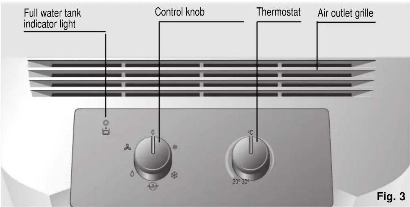
Control panel 23
Description of accessories....24
Requirements for use
Requirements for use 24
Transportation requirements ....25
Instructions for Use
Preparing the appliance....25
Ways of releasing air outdoors 26
Cooling....28
Dehumidification 29
Air purification ....29
Heating 30
Cleaning and Maintenance
Cleaning the appliance ....31
Cleaning and changing the purifying filters ....31
Storage requirements ....32
Prior to use at change of season ....32
Things to check before calling the Technical Service
General operation ....33
Noise ....33
Technical service / Warranty ....34
Recommendations for the disposal of packaging
□ Respect the environment when disposing of the packaging your appliance comes packed in.
☐ Our products are carefully packed for transportation. All of the material used in our packaging is environmentally friendly (the cardboard is manufactured from used paper) and may be recycled.
□ Recycling packaging helps conserve raw materials and reduces the amount of waste produced in the world.
□ Actively help protect the environment by disposing of packaging properly. Take it to your nearest local council disposal point or it may be possible to return it to your supplier.
Recommendations for the disposal of your old appliance
□ Unplug your appliance from the mains electricity supply and cut the power cable.
□ Appliances of this kind include both recyclable material, which may be used again, and hazardous products (such as heavy metals and liquid refrigerants), which may pollute the soil or the atmosphere. Actively help protect the environment by ensuring that your old appliance is disposed of in accordance with environmentally friendly practices. Dispose of your appliance at an official disposal or recycling point (ask your local council where the nearest disposal point is). Appliances of this kind contain refrigerants which must be disposed of in accordance with current regulations.
☐ This appliance is labelled in accordance with European Directive 2002/96/EG concerning used electrical and electronic appliances (waste electrical and electronic equipment - WEEE).
The guideline determines the framework for the return and recycling of used appliances as applicable throughout the EU.
natural_image
Symbol of a trash bin crossed with a diagonal line, no text or numbers presentRecommendations for saving energy
Your appliance consumes energy when in use. The consumption of energy produces an environmental impact. Energy consumption can be reduced enhancing the efficiency of your appliance.
□ Turn your air appliance off when it is not needed.
☐ Select an ideal temperature; excessively low temperatures result in high energy consumption.
☐ Locate your appliance away from possible heat sources (sunlight, etc.) and in a position with good air circulation.
☐ Ensure that your appliance is installed properly. The energy consumed can be cut by up to 30% by reducing the entry of heat into the room with awnings, blinds or curtains on glazed surfaces.
☐ Use the accessories supplied with your appliance and the specific accessories described in “Description of accessories” in order to minimise the entry of air from outdoors. When using accessories which require holes to be drilled in walls or windows, the hole should be as precise as possible and sealed with silicon, plaster or similar material to prevent air from flowing through any gaps.
□ It is recommended that you follow the manufacturer's instructions concerning the air expulsion tube (see "Preparing the appliance") in order to prevent efficiency loss and unnecessary energy consumption.
□ Avoid sharp bends on the air expulsion tube and do not lengthen it more than necessary.
☐ When expelling hot air through sliding windows, install the accessory which prevents hot air entering the room from outdoors and enhances efficiency.
☐ Make sure that the diffusion duct is positioned in such a way that the window can be closed as far as possible in order to prevent air from outdoors entering the room.
☐ Check that the sleeves (collection and diffusion) are correctly joined to the air expulsion tube. See “Ways of releasing air outdoors”
□ Make sure that the air intakes and outlets are not obstructed. Keep them clean and free of dirt, dust and foreign objects.
☐ Make sure that the filters fitted on your appliance are clean and installed properly (see “Cleaning and Maintenance”).
☐ In the summer, ventilate the building when the air outdoors is at its coolest (early morning, night).
Important Information
Before connecting your appliance
☐ Read the instructions book before using the appliance for the first time. It contains important information concerning not only how to use the appliance, but also maintenance and personal safety.
□ Keep this instructions book. It may be needed by another user at a later date.
☐ Do not use the appliance when damaged.
☐ Your appliance should be assembled and connected to the mains electricity supply in accordance with the assembly instructions and current regulations. You may lose your warranty if you fail to observe these instructions.
☐ Our appliances are manufactured in accordance with current safety regulations. Only technicians instructed in these matters are authorised to repair them. Your safety is at stake.
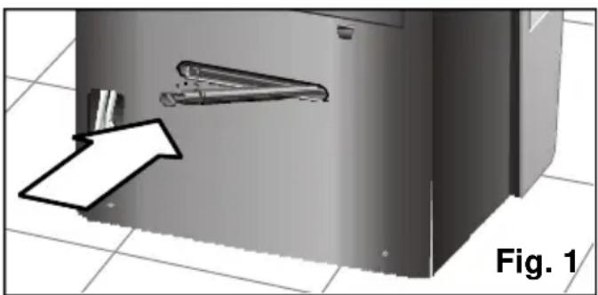
☐ Make sure that the drainage plug is fully inserted. It may have come loose during transportation, Fig. 1.
natural_image
3D diagram of a kitchen appliance with a handle and arrow, labeled Fig. 1 (no text or symbols on the main structure)☐ The manufacturer informs that these appliances are exclusively intended for household and/or commercial use, commercial being understood as offices or rooms, the size and characteristics of which comply with those specified in the commercial catalogues.
☐ The use of this appliance is not guaranteed for industrial environments, industrial being understood as large areas or in the proximity of non-ambient heat sources (elements, heaters, etc.).
If there are children in the home
☐ The front flap and the air-conditioning appliance must not be sat upon, climbed on or leant against. The appliance may fall over, hurting persons and/or damaging objects.
☐ Do not allow children to play or tamper with the air-conditioning appliance.
□ Keep small children away from the air-conditioning appliance, particularly when the front flap is open, to prevent them from hanging from or leaning against it. It may fall over.
☐ Do not allow children to play with or insert objects in the air outlets or any other cavity on the appliance.
Your new appliance
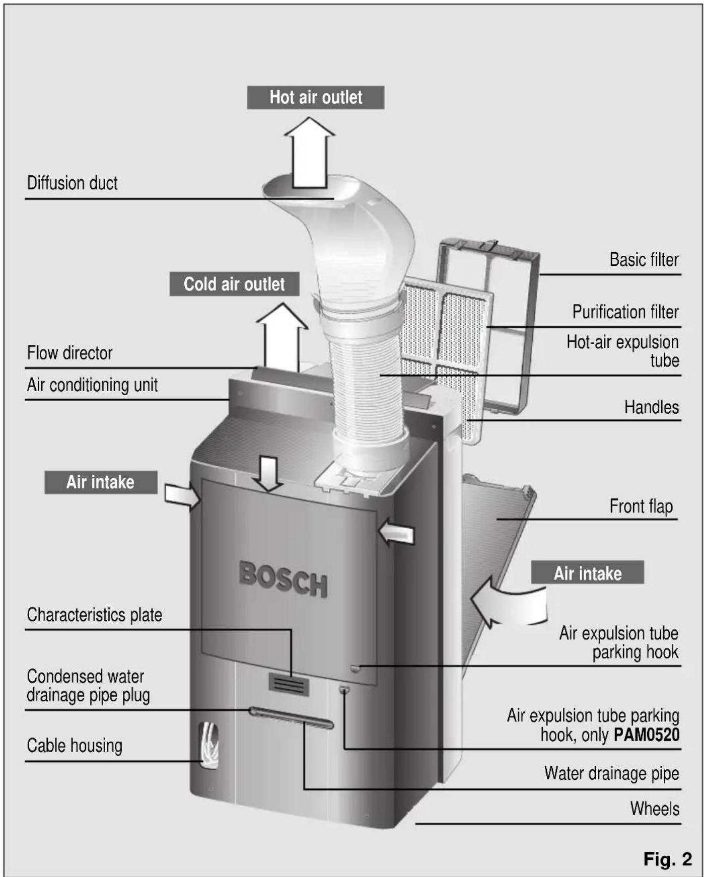
Description of the appliance
Your new appliance
Control panel
Model PAM0520 / PAM0540
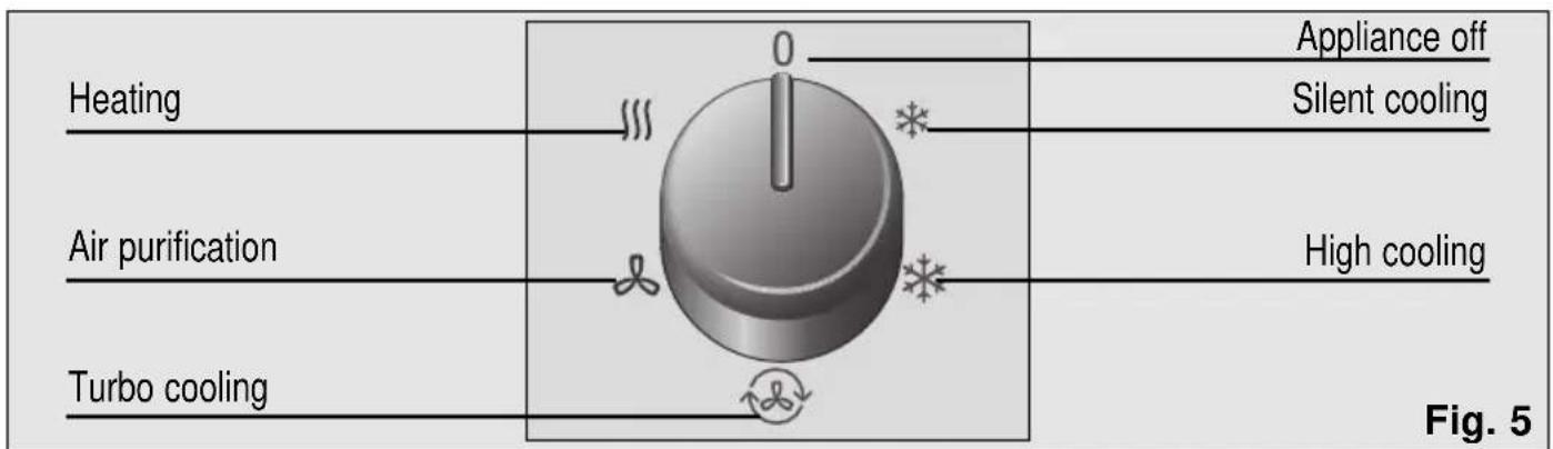
Model PAM0530
Description of accessories
| Suction Base Purifying Double wall grommet Sliding pad filter Filter active balcony | ||||||
| PAM0520 | √ | √ | ● | ● | ★ | |
| PAM0540 | √ | √ | √ | ● | ● | ★ |
| PAM0530 | √ | √ | √ | ● | ● | ★ |
| Approx. measurement min / max (length x width) cm. | ∅ wall 14 cm | 70x10/205x10 | ||||
√ Standard accessories: These accessories are supplied with the appliance.
- Optional accessories: These accessories are available for purchase from the manufacturer's official technical service and authorised distributors.
* Optional accessories: These accessories are only available for purchase from the manufacturer's official technical service.
Requirements for use
☐ This home appliance should be connected to a 220/240 V, 50 Hz mains electricity supply via an earthed socket.
☐ It must be protected with a 10 A slow-action fuse.
☐ Should an extension lead be required, then this lead should be at least 1.5 mm^2 thick per terminal, less than 25 m long and earthed.
☐ There is a cavity at the back of the appliance to house the mains electricity supply cable. See Fig. 2.
☐ Do not allow water to enter your appliance and do not cover the air intakes/outlets.
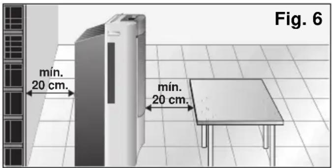
☐ For safety reasons, the appliance must be at least 20 cm away from any nearby surface before it is turned on, Fig. 6.
The mains electricity supply connection cable must only be replaced by authorised members of the manufacturer's Official Technical Service.
Requirements for use
Remember that when the appliance is turned off, it is necessary to wait for approximately 3 minutes before turning it back on again. This period of time is required in order to ensure correct appliance operation.
Avoid direct contact with the air expelled through the expulsion tube.
Transportation requirements
The appliance is fitted with wheels to make it easier to move around. If necessary, you can tilt the appliance in order to move it. You should not turn the appliance back on again for a minimum period of one hour after performing this procedure.
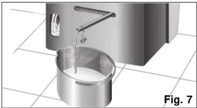
Before tilting it, empty the condensed water from the internal tank by extracting the water drainage pipe from its housing and removing the plug, Fig. 7. Do not forget to replace the plug and reinsert the pipe in its housing when the tank is empty.
natural_image
Illustration of a kitchen sink pouring milk into a bucket on tiled floor (no text or symbols)Instructions for Use
Preparing the appliance
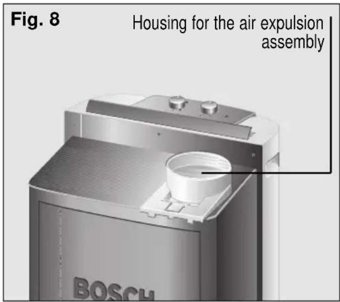
Fitting the air expulsion tube and accessories onto the appliance
Fit the air expulsion tube onto the fixture with the "push" tab and thread it anti-clockwise, Fig. 8.
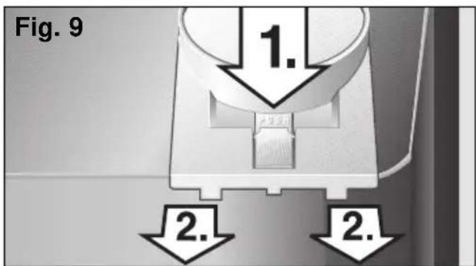
If easier, the housing can also be removed from the appliance by pressing the "Push" tab and sliding it out, Fig. 9.
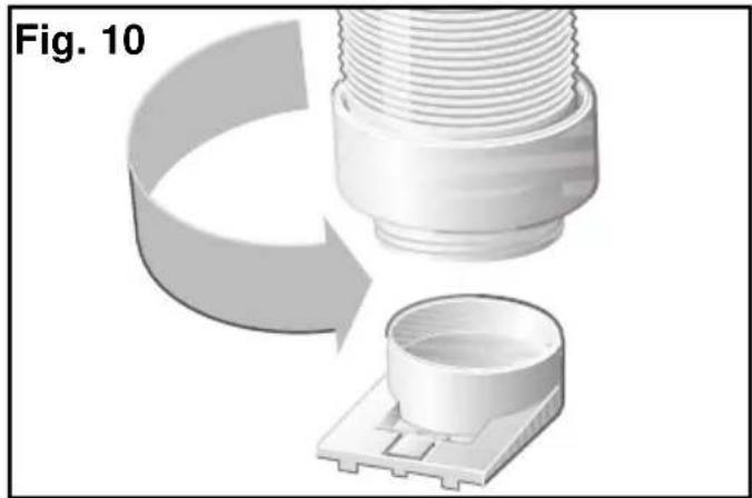
Once out, thread the expulsion tube as shown on Fig. 10, making sure that it is properly secured.
natural_image
3D rendering of a mechanical component with threaded top and base, showing a curved arrow indicating rotation or assembly (no text or symbols)Then fit the assembly onto the appliance by slotting it into position Fig. 11.
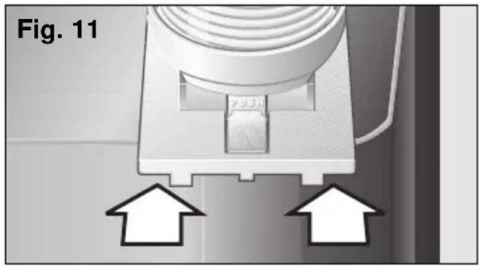
natural_image
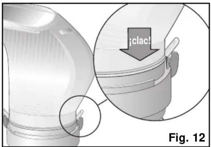
Close-up of a mechanical component with two white arrows pointing to a central feature, labeled 'Fig. 11' (no readable text or symbols beyond label)Securing the diffusion duct onto the air expulsion tube
Fit the diffusion duct onto the free end of the tube pushing both parts gently until the duct clicks into place. Make sure that the clips are closed. Otherwise, the duct may fall off. Fig 12.
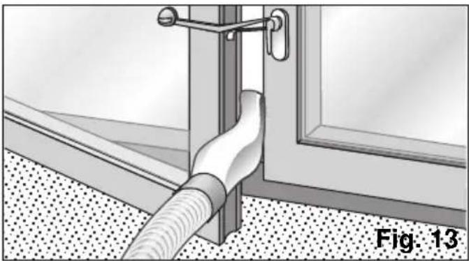
Ways of releasing air outdoors Temporary installation
☐ Open the window slightly and position the diffusion duct between the jamb and the glaze frame.
☐ Close the window as far as possible and secure it with the suction pad supplied, Fig. 13.
natural_image
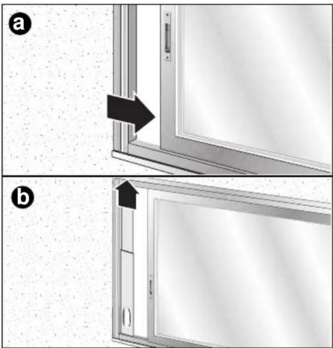
Diagram of a wall-mounted hose assembly with a door, showing structural details (no text or symbols)- The sliding window/balcony installation accessory can also be used (See "Description of accessories"). Fig. 14: a, b, c, d. This accessory can be used for both horizontal and vertical windows / balconies.
natural_image
Two-panel diagram showing a door opening process with arrows indicating direction (no text or symbols)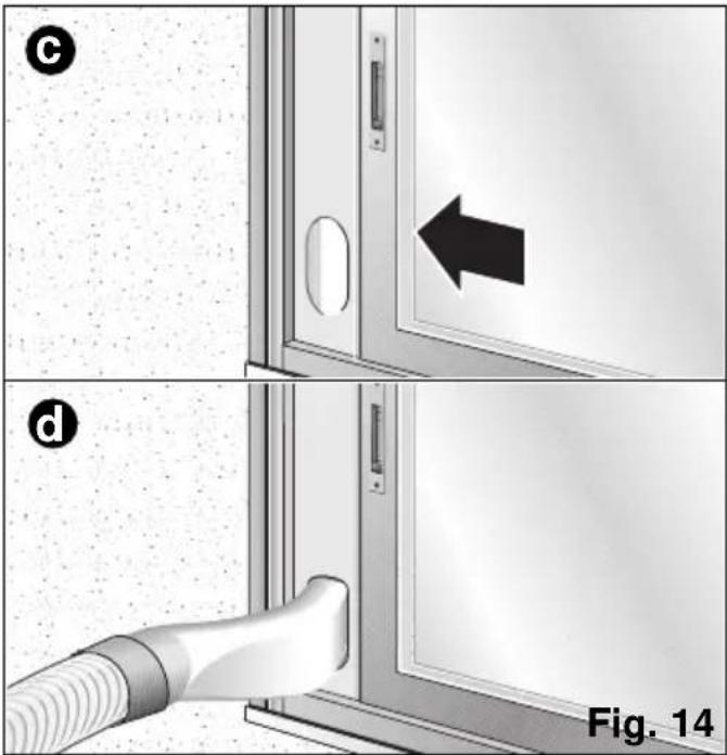
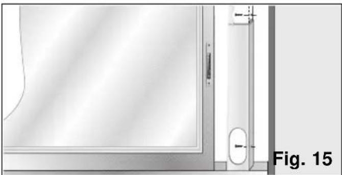
- The accessory has two holes on the side to fit it to the window / balcony with. The user can secure it to the frame or wall with two screws (not included with the accessory) to prevent it from moving or falling out of place, Fig. 15.
natural_image
Technical diagram showing a door with a wall-mounted fixture and a labeled section 'Fig. 15' (no readable text or symbols beyond label)Permanent installation
Permanent installation is performed using the wall grommet. See "Description of accessories".
☐ To expel hot air through the wall, it is necessary to make an 14-cm diameter hole in the wall and fit the wall grommet, Fig. 16.
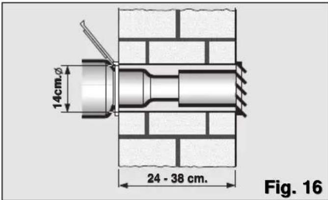
□ Remove the diffusion sleeve and connect the air expulsion tube to the accessory.
Notes
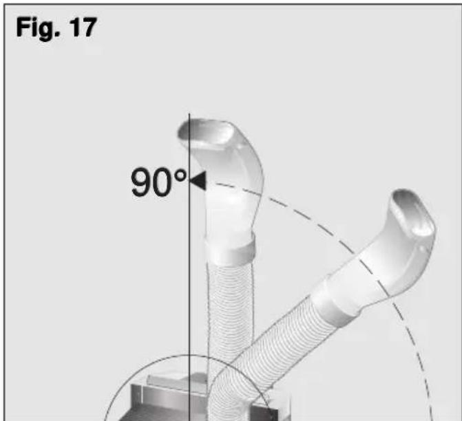
Do not extend the hot air expulsion tube more than necessary (maximum length; 140 cm).
Do not form sharp bends when positioning the tube, otherwise the correct expulsion of hot air may be impeded. This may cause a reduction in the cooling power and performance of the appliance.
In order to achieve maximum cooling efficiency and minimum noise levels, the expulsion tube should be fitted above the total height of the appliance, Fig. 17.
Cooling
The appliance cools and dehumidifies the air in the room at the same time in order to create a pleasant atmosphere.
□ Plug the appliance into the mains electricity supply.
☐ Lead the hot air expulsion tube outside. In order to avoid excessive noise and efficiency loss, the air expulsion tube should be positioned as shown in Fig. 13. See "Ways of releasing air outdoors".
☐ Check that the plug, Fig. 1, is fitted on the drainage pipe to prevent water from leaking onto the support surface.
☐ Lift the air director on the top of the appliance. This air director is not installed on the appliance on PAM0530 models. See figures 25 and 26 in "Heating".
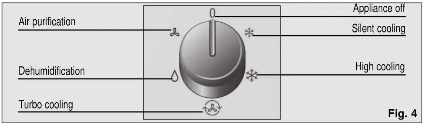
□ Select the silent *, high * or turbo cooling function, Fig. 18.
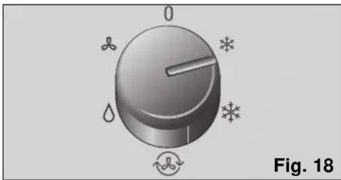
natural_image
Circular dial indicator with icons for humidity, snowflake, and cooling (no text or labels)☐ Set the thermostat to the desired temperature, Fig. 19. If the appliance turns itself off automatically because the temperature set for the room has been reached and, it is necessary to wait for ambient temperature to rise 2-3°C before it comes back on again.

During air conditioning, some of the condensed water produced evaporates automatically and is expelled outdoors together with the expelled air through the hot air expulsion tube.
In conditions of extreme humidity, the appliance accumulates condensed water in an internal tank. When a certain level is reached an indicator light, Fig. 3, comes on indicating that the condensed water tank is full and needs to be emptied. When this happens, the appliance stops cooling the air in the room until the water is drained, as explained in "Transportation requirements", Fig. 7.
☐ It is recommended that you turn the appliance off while draining the water.
Warning!
Remember that when the appliance is turned off, it is necessary to wait for approximately 3 minutes before turning it back on again. This period of time is required in order to ensure correct appliance operation.
Dehumidification
In this operation function, the appliance reduces the humidity in the atmosphere and purifies the air.
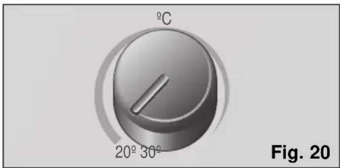
☐ Set the thermostat to its minimum temperature setting, Fig. 20.
Instructions for Use
☐ Place a bowl at the drainage pipe outlet and remove the plug to collect the condensed water, Fig. 21.
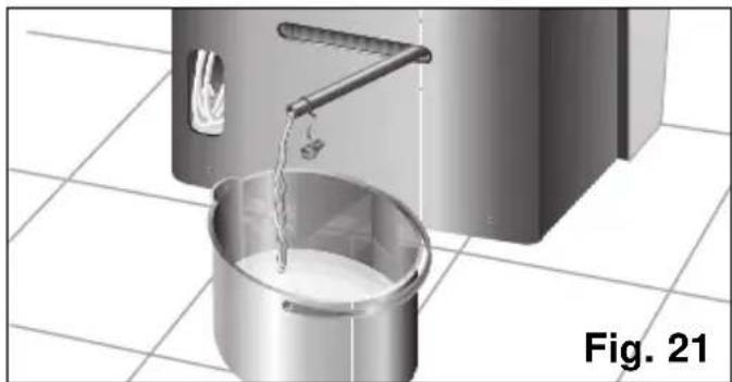
natural_image
3D rendering of a kitchen sink pouring liquid into a bucket on tiled floor (no text or symbols)☐ Remove the diffusion duct and set the air expulsion tube to the position shown in ..... fig 22.
☐ The expulsion tube may also be totally dismantled if desired.
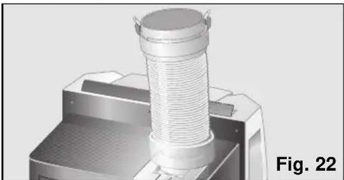
natural_image
3D rendering of a mechanical component with a coiled spring and mounting base, labeled Fig. 22 (no text or symbols on the object itself)☐ Lift the air director on the top of the appliance. This air director is not installed on the appliance on PAM0530 models. See figures 26 and 27 in "Heating".
□ Plug the appliance into the mains electricity supply.
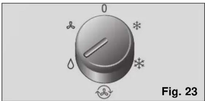
☐ Set the control knob to the dehumidification function depending on the model of your air-conditioning appliance.
□ Models with electric heating * ; other models △.
natural_image
3D rendered knob with leaf and swirl symbols, labeled Fig. 23 (no text or numbers on the knob itself)Warning!
The amount of water dehumidified may vary depending on ambient conditions (See "Technical Information").
Do not forget to replace the plug onto the water drainage pipe when you change function, otherwise the appliance will shed water when operated.
Remember that ambient temperature must be 18°C or higher in order for the appliance to work.
In this operation function, room temperature rises slightly.
Air purification
The air inside the room (ventilation) is circulated through a filtering system when the appliance is set to this function.
The appliance comes with a basic filter (already fitted on the appliance) and a purifying filter (except on models PAM0520) to be fitted by the user-See "Fitting the purifying filter (double active)"- against:
- Pollen, bacteria and dust.
☐ Put the air expulsion tube in the same position as for dehumidification.
☐ Lift the air director on the top of the appliance. This air director is not installed on the appliance on PAM0530 models. See figures 25 and 26 in "Heating".
□ Plug the appliance into the mains electricity supply.
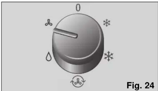
☐ Set the control knob to the air-purification function ✿ Fig. 24.
natural_image
3D rendered knob with labeled degrees (0, 0, 0, 0) and decorative symbols (no readable text or numbers)Instructions for Use
☐ When the appliance or the model is fitted with optional filters, we recommend that these be left on regardless of the function selected (cooling, dehumidification, air purification) in order to purify the air more effectively.
Note:
Due to the internal configuration of the PAM0520 models, air is also expelled outdoors when the appliance is set to the ventilation function. In order to reduce the noise produced, it is recommended that you remove the air expulsion tube.
Heating (only on PAM0530)
When set to position , the appliance heats the air in the room until the temperature set by the user is reached. The air in the room is purified at the same time.
□ Plug the appliance into the mains electricity supply.
☐ Put the air expulsion tube in the same position as for dehumidification.
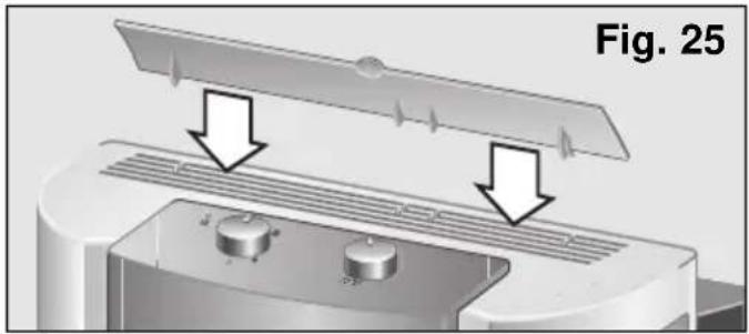
☐ This air director is not installed on the appliance on PAM0530 models. The manufacturer recommends that an air director be previously installed in order to distribute the air flow better. The director is fitted as shown in the following figures.
natural_image
Diagram of a device with two arrows indicating downward motion, showing internal components and ventilation (no text or symbols)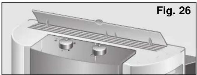
natural_image
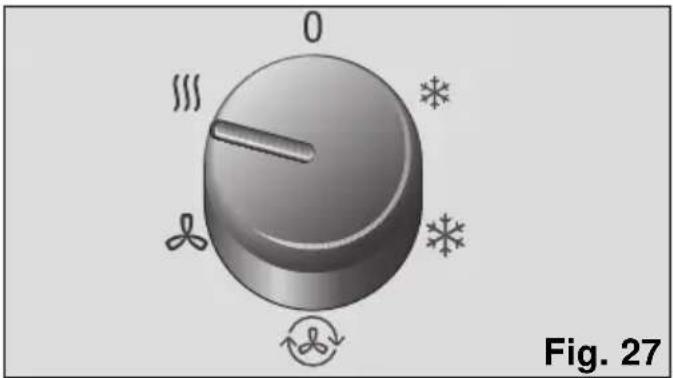
3D rendered mechanical component with two circular ports and a lid, labeled Fig. 26 (no text or symbols on the component itself)□ Select the heating function, Fig. 27.
natural_image
3D rendered knob with labeled degrees (0, 1/3, 3/4) and decorative symbols (no readable text or numbers)☐ Set the thermostat to the desired temperature. When this temperature is reached, the appliance turns itself off automatically. It comes back on again when the temperature drops 2-3°C.
Warning!
Do not cover the air intakes or outlets on your appliance!
Cleaning and Maintenance
Cleaning the appliance
☐ For safety reasons, you should unplug the appliance from the mains electricity supply before cleaning.
☐ The appliance can be cleaned with a cloth or sponge, slightly warm water and a mild detergent.
□ Never use hot water (more than 40°C), bleach, petrol, acid, scouring pads, brushes or strong detergents. Prevent water from entering the appliance.
☐ Do not clean the appliance with a water hose or compressed air.
Cleaning and changing the purifying filters
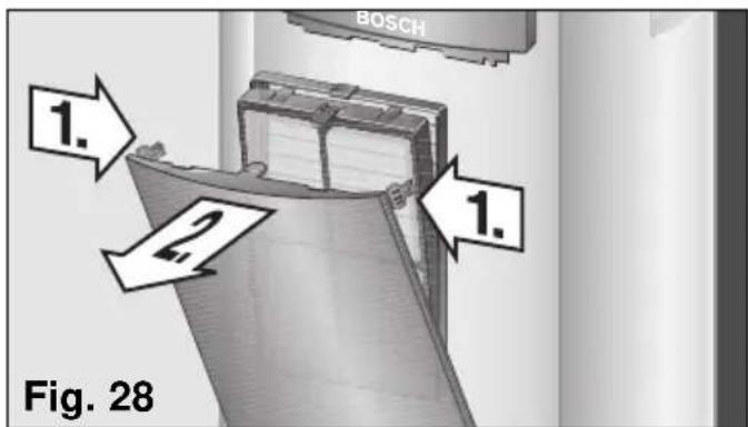
Press the side tabs, (Fig. 28, 1.), on the front flap of the appliance and pull it open (it is not necessary to remove it), (Fig. 28, 2.). The flap is fitted with a stop and can be opened up to this point without risk of falling.
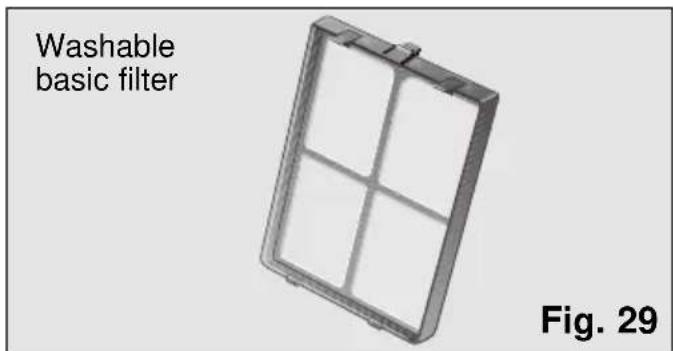
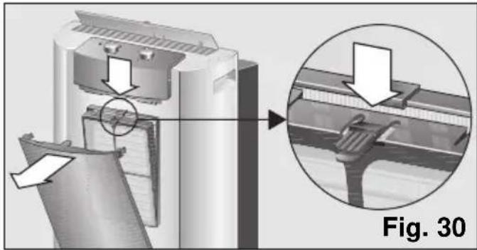
All models are fitted with a basic filter which needs to be cleaned regularly, Fig. 29. The filter is accessed by pressing the tab at the top and removing it from its housing, Fig. 30. The filter is cleaned under a cold tap, dried and replaced.
Warning!
Do not try to clean the basic filter in a dishwasher. The plastic on the basic filter is not suitable for dishwashers and is unable to withstand the high temperatures involved in washing programmes. It will deform and may even break.
natural_image
Technical illustration of a mechanical device with an inset magnified view showing internal components (no text or symbols)The purifying filter supplied with the appliance (according to models) is to be fitted by the user (See "Fitting the purifying filter (double active").
The purifying filter further purifies the air in the room which passes through the appliance.
When the purifying filter is fitted, the appliance's cooling capacity may drop slightly. This is particularly the case when the filter is saturated or damaged. It is, therefore, recommended that you check and change the filter at least once a year.
(These accessories are available for purchase from the Manufacturer's Official Technical Service and authorised distributors). See "Description of accessories".
Fitting the purifying filter (double active)
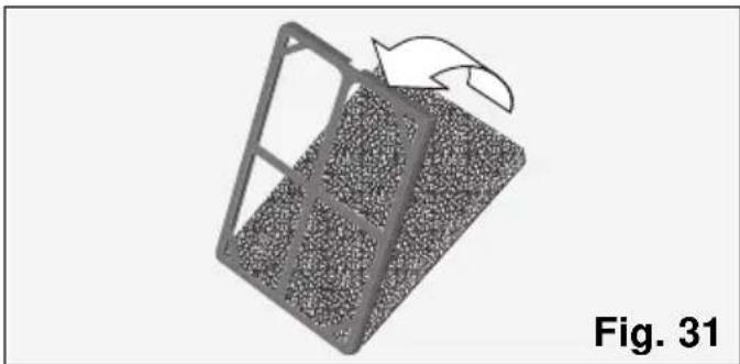
- Check that the purifying filter is fitted in the positioner. If it is not, fit as shown on Fig 31
natural_image
Diagram of a mechanical component with a rotating arrow indicating rotation, labeled 'Fig. 31' (no text or symbols on the diagram itself)Cleaning and Maintenance
- Remove the basic filter from the appliance, Fig. 30.
- Insert the purifying filter + positioner inside the basic filter as shown on Fig. 32, remembering that it must be housed on the lower studs first.
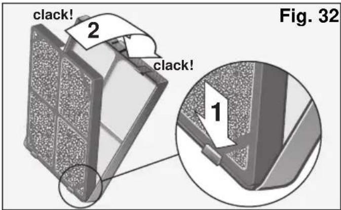
• Install the assembly onto the appliance by lining the lower studs up with the slots on the front casing of the appliance and pressing the top clip in until it clicks into position. The assembly is fitted properly when it clicks into position.
- Close the front flap
Warning!
Fit only one set of filters onto the support in order to ensure correct appliance operation.
Note
The front flap can also be removed in order to clean the appliance or change the filters more easily.
To do this, open the flap up to the safety stop (the flap opens to a slight angle, Fig. 19) and pull outwards. In order to refit it, line the lower studs on the flap up with the holes on the casing until the studs meet the clips on the casing.
Storage requirements
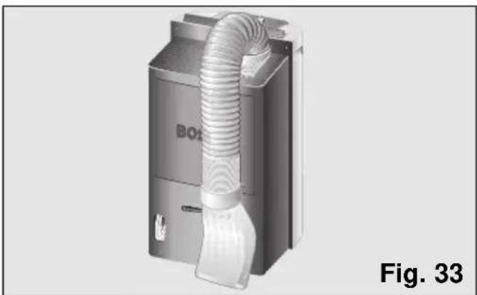
When the appliance is out of use for a long period, set the expulsion tube to parking position so that the appliance takes up as little space as possible.
☐ To do this, bend the tube towards the back of the appliance and secure it with the diffusion hook. Figs. 33 and 34.
natural_image
3D rendering of a BO4 air duct system with a white plastic clip, labeled Fig. 33 (no text or symbols on the device itself)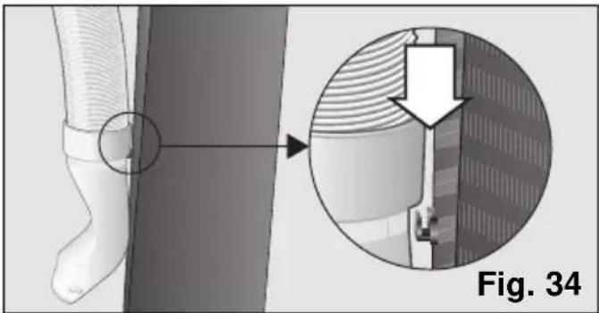
natural_image
Medical illustration showing a foot with a circular arrow pointing to a detailed view of a mechanical component (no text or symbols present)Prior to use at change of season
□ Clean the air filter.
□ Clean the casing and the grilles if necessary.
General requirements for operation What to do if...
... the appliance does not work ...
☐ Check that it is plugged in properly.
□ Make sure that the control knob is not set to off ●.
☐ Check that the mains electricity supply is working. Check the fuse box.
☐ Set the thermostat to its minimum temperature position.
... the appliance does not work and the light indicating that the condensed water tank is full is on ...
☐ Set the appliance on a flat surface. If the light does not go out, empty the internal water tank. (See instructions in “cooling”).
... the appliance does not work and the light indicating that the condensed water tank is full flashes...
☐ This indicates heat sensor failure. Get in touch with the Technical Assistance Network.
... the appliance does not reduce room temperature sufficiently ...
☐ Check the joins on the hot air expulsion tube.
☐ Make sure that the expulsion tube is not too bent and that it is not extended to more than 140 cm.
□ Make sure that the plug is fitted on the drainage water pipe.
☐ Fit the suction pad to close the window as far as possible.
☐ Lower blinds to reduce direct sunlight.
... there is water on the control panel grille or on the basic filter housing ...
☐ There is no cause for concern. This is normal.
Noise
... the appliance makes a lot of noise ...
Some noise is normal and other types of noise can be solved easily. You need to be able to distinguish between these types of noise:
Perfectly normal noise
☐ The sound of water flowing in cycles is due to the pump, which circulates the water to enhance the power of the appliance.
☐ A dull, humming sound is inevitable due to the compressor.
☐ A faint, whistling sound is due to the refrigerant passing through the thinner pipes on the appliance when the compressor starts up.
☐ A short clicking sound is produced when the pump connects and disconnects or when the regulator connects or disconnects the electronics system.
Easy-to-solve noises
□ Make sure that the air expulsion tube and the diffusion and collection sleeves are fitted properly onto the appliance.
□ Make sure that the air intakes and outlets on the appliance are free of obstacles.
☐ Make sure that the appliance is not in direct contact with furniture or other appliances. The air output may be flowing directly onto these and thereby increasing the noise level.
Any other type of fault or repair work should be dealt with by a specialised Technician. Get in touch with your authorised dealer, customer service or the Technical Service Network.
Technical service / Warranty
Technical service
Should your appliance fail to work properly and all the instructions for use and installation (especially the section headed "Requirements....") have been carefully observed, then remember that our Technical Service Network is at your full disposal.
When contacting the Technical Service, quote the model code (E-NR) and the appliance's factory number (FD). This information can be found on characteristics plate, Fig. 2.
Warranty
The conditions of warranty depend on the relevant Supplier in a particular country. Contact the establishment where you purchased your appliance for more information and quote the appliance model and factory number. The receipt of purchase for the appliance must be produced prior to any work carried out under warranty.
Sommaire
Conditions de transport ....41
Mode d'Emploi
natural_image
Symbol of a trash bin crossed with no text or labels
natural_image
3D diagram of a refrigerator with a handle and arrow pointing to the front panel, labeled Fig. 1 (no text or symbols on the main object)Conditions de transport
natural_image
Illustration of a kitchen mixer with a bucket pouring liquid, placed on tiled floor (no text or symbols)Mode d'Emploi
natural_image
3D rendering of a mechanical component with threaded end and base, shown in two views (no text or symbols)natural_image
Close-up of a mechanical component with two upward-pointing arrows indicating movement or force, labeled 'Fig. 11' (no text or symbols on the object itself)natural_image
Diagram of a hose being inserted into a door frame, labeled Fig. 13 (no text or symbols on the diagram itself)natural_image
Exterior view of a door with an arrow pointing to the side panel (no text or symbols visible)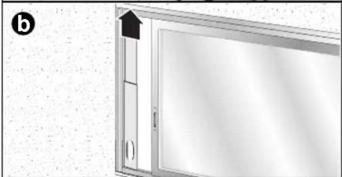
natural_image
Exterior view of a door with an arrow pointing upward, no visible text or symbolsMode d'Emploi

natural_image
Technical diagram showing a door frame with a labeled section 'Fig. 15' (no readable text or symbols beyond label)Installation fixe
natural_image
Close-up of a circular mechanical knob with labeled degrees (0, 1, 2) and decorative symbols around it, marked as Fig. 18 (no text or numbers on the knob itself)natural_image
Illustration of a kitchen sink pouring liquid into a bucket on tiled floor (no text or symbols)natural_image
3D rendered mechanical component with threaded cylindrical body and base, labeled Fig. 22 (no text or symbols on the object itself)natural_image
3D rendered knob with leaf and swirl icons, labeled Fig. 23 (no text or symbols on the knob itself)Attention!
natural_image
3D rendered knob with directional arrows and symbols (no text or labels)natural_image
Diagram of a device with ventilation grilles and control buttons, labeled Fig. 25 (no text or symbols on diagram itself)
natural_image
3D rendering of a mechanical component with two circular ports and a lid, labeled Fig. 26 (no text or symbols on the diagram itself)natural_image
3D rendered knob with directional arrows and snowflake symbols, labeled Fig. 27 (no text or numbers on the knob itself)natural_image
Technical illustration of a mechanical component with an inset magnified view showing a detail (no text or symbols present)natural_image
3D diagram of a mechanical component with a curved arrow indicating rotation, labeled 'Fig. 31' (no text or symbols on the diagram itself)natural_image
3D rendering of a BOB air conditioner unit with coiled tubing, labeled Fig. 33 (no text or symbols on the device itself)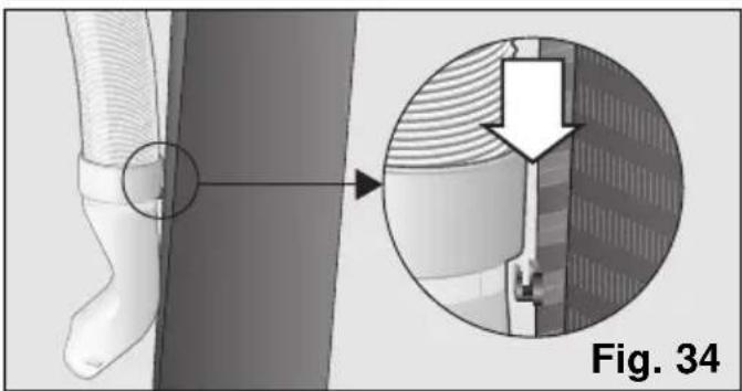
natural_image
Medical illustration showing a foot with a magnified inset of internal tissue structure, labeled Fig. 34 (no text or symbols on the diagram itself)natural_image
Symbol of a trash bin with crossed lines indicating no waste, and a black rectangle below (no text or labels)natural_image
3D diagram of a kitchen appliance with a handle and arrow pointing to a component, labeled Fig. 1 (no text or symbols on the main structure)natural_image
Illustration of a kitchen appliance pouring milk into a bucket on tiled floor (no text or symbols)natural_image
3D diagram showing a pipe fitting with a magnified inset view, labeled 'Fig. 10' (no text or symbols on the diagram itself)natural_image
Close-up of a mechanical component with two white arrows pointing to a central feature, labeled 'Fig. 11' (no text or symbols on the object itself)natural_image
Diagram of a wall-mounted hose assembly with a handle, showing structural components and floor flooring (no text or symbols)natural_image
Two-panel diagram showing a door opening with an arrow indicating direction, labeled (a) and (b), both without any text or symbols.
natural_image
Technical diagram showing a door frame with a labeled section 'Fig. 15' (no readable text or symbols beyond label)Instalación fija
natural_image
Circular dial indicator with icons for humidity, water, snowflake, and leaf (no text or labels)natural_image
Illustration of a kitchen sink pouring liquid into a bucket on tiled floor, labeled Fig. 21 (no text or symbols on the diagram itself)natural_image
3D rendered mechanical component with threaded cylindrical body and base, labeled Fig. 22 (no text or symbols on the object itself)natural_image
3D rendered knob with leaf and swirl icons, labeled Fig. 23 (no text or symbols on the knob itself)¡Atención!
natural_image
3D rendered knob with labeled degrees (0, 0, 0) and decorative symbols (no readable text or numbers)natural_image
Diagram of a device with ventilation grilles and a lid, showing two downward arrows indicating airflow or movement (no text or symbols present)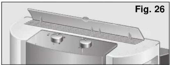
natural_image
3D rendering of a mechanical component with two circular ports and a lid, labeled Fig. 26 (no text or symbols on the diagram itself)natural_image
3D rendered knob with directional arrows and symbols (no readable text or labels)natural_image
Technical illustration of a mechanical device with an inset magnified view showing internal components (no text or symbols)natural_image
3D diagram of a mechanical component with a curved arrow indicating rotation, labeled 'Fig. 31' (no text or symbols on the diagram itself)natural_image
3D rendering of a BOE air conditioner unit with coiled tubing and a connector, labeled Fig. 33 (no text or symbols on the device itself)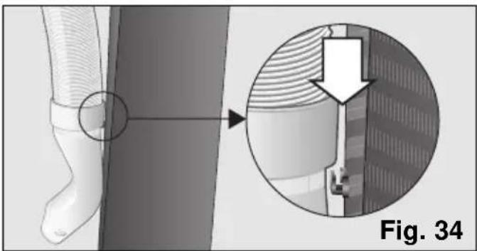
natural_image
Medical illustration showing a foot with a bandage and a magnified view of a mechanical component (no text or symbols)natural_image
Symbol of a trash bin with crossed lines indicating no waste or discharge, and a black rectangle below (no text or labels)natural_image
3D diagram of a refrigerator with a handle and arrow pointing to the front panel, labeled Fig. 1 (no text or symbols on the main object)natural_image
Illustration of a kitchen sink pouring liquid into a bucket on tiled floor, labeled Fig. 7 (no text or symbols on the diagram itself)Instruções de Uso
natural_image
3D rendering of a mechanical component with threaded shaft and base, shown in two views (no text or symbols)natural_image
Close-up of a mechanical component with two white arrows pointing to a central feature, labeled 'Fig. 11' (no text or symbols on the object itself)natural_image
Diagram of a wall-mounted hose assembly with a handle, showing structural components and floor flooring (no text or symbols)natural_image
Two-panel diagram showing a door opening with an arrow indicating direction, labeled (a) and (b), both without any text or symbols.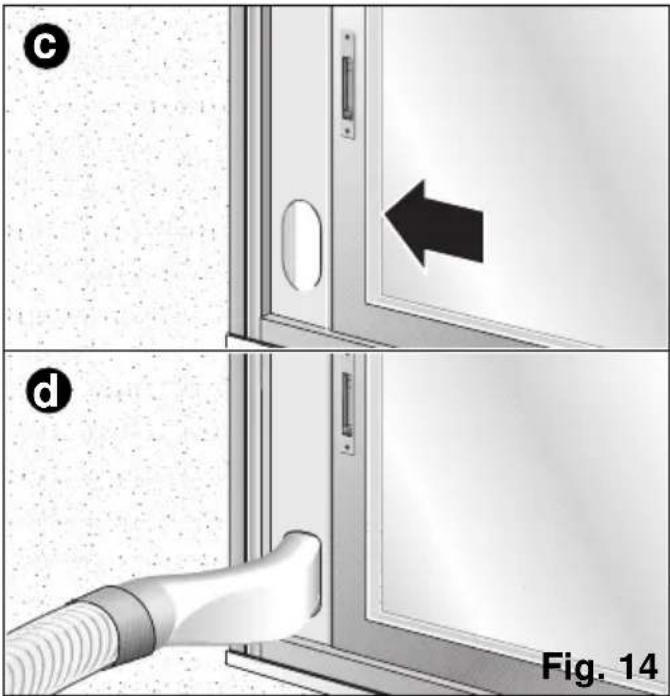
natural_image
Technical diagram showing a door frame with a labeled section 'Fig. 15' (no readable text or symbols beyond label)Instalação fixa
natural_image
Close-up of a circular dial with leaf symbols and a pointer, labeled Fig. 18 (no text or numbers on the dial itself)natural_image
Illustration of a bucket pouring liquid into a container on tiled floor, with no visible text or symbolsnatural_image
3D rendered mechanical component with threaded cylindrical body and base, labeled Fig. 22 (no text or symbols on the object itself)natural_image
3D rendered knob with labeled directional indicators (no text or symbols on the knob itself)Atenção!
natural_image
3D rendered knob with labeled degrees (0, 0, 0) and decorative symbols (no readable text or numbers)natural_image
Diagram of a device with ventilation grilles and a lid, showing airflow direction (no text or symbols)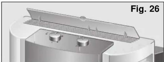
natural_image
3D rendered mechanical component with two circular ports and a lid, labeled Fig. 26 (no text or symbols on the component itself)natural_image
3D rendered knob with directional arrows and symbols (no readable text or labels)natural_image
Technical illustration of a mechanical device with an inset close-up showing a detail (no text or symbols present)natural_image
3D diagram of a mechanical component with a curved arrow indicating rotation, labeled Fig. 31 (no text or symbols on the diagram itself)natural_image
3D rendering of a BOS air conditioner unit with coiled tubing and a handle, labeled Fig. 33 (no text or symbols on the device itself)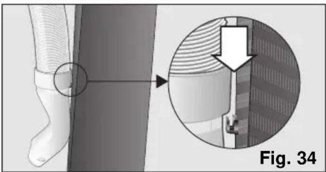
natural_image
Medical illustration showing a foot with a bandage and a magnified view of internal tissue structure (no text or symbols)natural_image
Symbol of a trash bin crossed with two crossed lines, representing waste or discharge (no text or labels)
natural_image
3D diagram of a kitchen appliance with a handle and arrow, labeled Fig. 1 (no text or symbols on the main diagram)natural_image
3D rendering of a kitchen sink pouring liquid into a bucket on tiled floor, labeled Fig. 7 (no text or symbols on the diagram itself)natural_image
3D rendering of a mechanical component with threaded top and base, showing a curved arrow indicating rotation (no text or symbols)natural_image
Mechanical component diagram showing a base with two upward arrows indicating motion or force (no text or symbols present)natural_image
Illustration of a hand holding a flexible hose to connect a window frame (no text or symbols visible)natural_image
Diagram showing two steps (a and b) of a door opening with arrows indicating direction, no text or symbols present.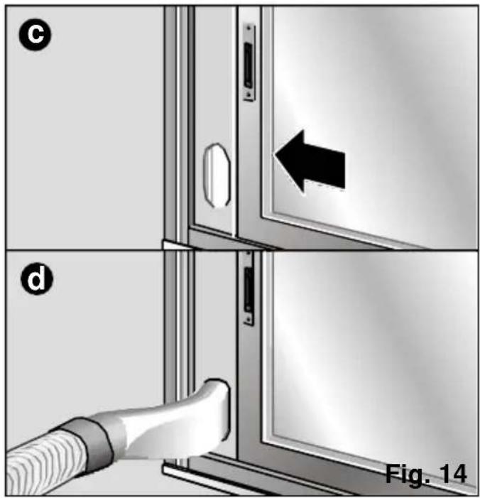
natural_image
Technical diagram showing a window with a door and a vertical panel, labeled Fig. 15 (no text or symbols on the diagram itself)Vaste installatie
natural_image
Simple grayscale icon of a helmet with surrounding symbols (no text or labels)natural_image
3D rendering of a kitchen sink pouring liquid into a bucket on tiled floor (no text or symbols)natural_image
3D mechanical component with coiled spring and housing, labeled Fig. 22 (no text or symbols on the object itself)natural_image
Illustration of a stylized 3D object with surrounding geometric shapes (no text or symbols)Let op!
natural_image
Illustration of a stylized helmet with decorative elements, labeled 'Fig. 24' (no text or symbols on the helmet itself)Verwarming (alleen in model PAM0530
natural_image
Diagram of a device with two buttons and ventilation slots, labeled Fig. 25 (no text or symbols on the diagram itself)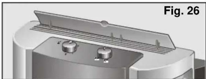
natural_image
3D mechanical component diagram labeled Fig. 26, showing a cylindrical component with two side holes and a flat top surface (no text or symbols on the main structure)natural_image
Illustration of a mechanical knob with labeled parts (no text or symbols on the knob itself)natural_image
Technical illustration of a mechanical component with an inset magnified view showing a detail (no text or symbols present)natural_image
3D diagram of a rectangular frame with internal grid pattern and an arrow indicating rotation (no text or symbols)natural_image
3D rendering of a mechanical device with coiled tubing and a labeled part (Fig. 33), no readable text or symbols beyond labels.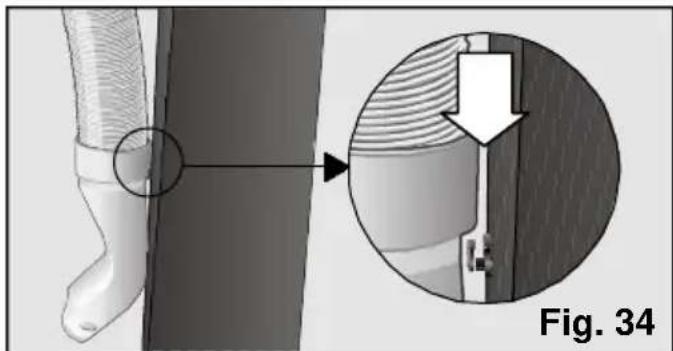
natural_image
Medical illustration showing a foot with a magnified view of internal tissue structure, labeled Fig. 34 (no text or symbols on the diagram itself)natural_image
Symbol of a trash bin crossed with two crossed lines, representing waste or discharge (no text or labels)
natural_image
3D diagram of a kitchen appliance with a handle and arrow, labeled Fig. 1 (no text or symbols on the main subject)natural_image
Illustration of a kitchen mixer with a bucket pouring liquid, placed on tiled floor (no text or symbols)Istruzioni d'uso
natural_image
3D rendering of a mechanical component with threaded end and base, shown in two views (no text or symbols)natural_image
Close-up of a mechanical component with two upward-pointing arrows indicating motion or assembly (no text or symbols)natural_image
Diagram of a wall-mounted hose assembly with a handle, showing structural details (no text or symbols)natural_image
Two-panel diagram showing a door opening with an arrow indicating direction, labeled (a) and (b), both without any text or symbols.
natural_image
Technical diagram showing a door frame with a vertical door and a labeled section 'Fig. 15' (no readable text or symbols beyond label)Installazione fissa
natural_image
Close-up of a circular dial with labeled zones (no text or symbols on the dial itself)natural_image
Illustration of a kitchen sink pouring milk into a bucket on tiled floor, labeled Fig. 21 (no text or symbols on the diagram itself)natural_image
3D rendering of a mechanical component with a coiled spring and top housing, labeled Fig. 22 (no text or symbols on the object itself)natural_image
Close-up of a circular mechanical knob with directional arrows and symbols (no readable text or labels)Attenzione!
natural_image
3D rendered knob with directional arrows and symbols (no text or labels)natural_image
Diagram of a device with two buttons and ventilation slots, labeled Fig. 25 (no text or symbols on the diagram itself)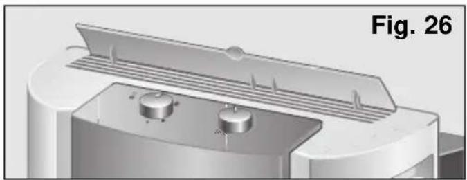
natural_image
3D rendering of a mechanical component with two circular ports and a lid, labeled Fig. 26 (no text or symbols on the diagram itself)natural_image
Close-up of a circular knob with directional arrows and symbols (no readable text or labels)natural_image
3D rendering of a rectangular metal frame with four internal grid lines (no text or symbols)Fig. 29
natural_image
Technical illustration of a mechanical component with an inset magnified view showing a detail (no text or symbols present)natural_image
Diagram of a mechanical component with a curved arrow indicating rotation or force direction (no text or symbols)Fig. 31
natural_image
3D rendering of a BO2 air duct system with coiled tubing, labeled as Fig. 33 (no text or symbols on the device itself)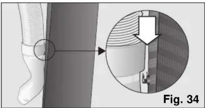
natural_image
Medical illustration showing a surgical procedure on a foot with an arrow indicating direction (no text or symbols present)natural_image
Symbol of a trash bin crossed with no text or labels
Så sparar Du energi
natural_image
3D diagram of a refrigerator with a handle and arrow pointing to the door, labeled Fig. 1 (no text or symbols on the diagram itself)natural_image
Illustration of a kitchen appliance pouring liquid into a bucket on tiled floor, labeled Bild. 7 (no text or symbols on the main subject)natural_image
3D rendering of a plastic connector with threaded body and base, shown in two views (no text or symbols)natural_image
Close-up of a mechanical component with two upward-pointing arrows indicating motion or assembly (no text or symbols)natural_image
Diagram of a wall-mounted hose assembly with a door handle, showing structural details (no text or symbols)natural_image
Two-panel diagram showing a door opening with an arrow indicating direction, labeled (a) and (b), both without any text or symbols.
natural_image
Architectural detail view of a window with a door and vertical panel, labeled 'Bild. 15' (no other text or symbols)Fast installation
natural_image
Circular dial indicator with leaf and snow symbols, labeled Bild. 18 (no text or numbers on the dial itself)natural_image
Illustration of a kitchen mixer pouring liquid into a bucket on tiled floor (no text or symbols)natural_image
3D rendered mechanical component with threaded cylindrical body and base, labeled Bild. 22 (no text or symbols on the object itself)natural_image
3D rendered knob with leaf and swirl symbols, labeled Bild. 23 (no text or numbers on the knob itself)OBS!
natural_image
3D rendered knob with leaf and snowflake symbols, labeled Bild. 24 (no text or numbers on the knob itself)natural_image
Diagram of a device with ventilation grilles and two labeled components (no text or symbols)
natural_image
3D rendered mechanical component with two circular adjustment knobs and a lid, labeled Bild. 26 (no text or symbols on the component itself)natural_image
3D rendered knob with directional arrows and symbols (no readable text or labels)natural_image
3D rendering of a rectangular metal frame with four internal square cutouts (no text or symbols)Bild. 29
natural_image
Technical illustration of a mechanical component with an inset magnified view showing detail (no text or symbols)natural_image
Diagram of a container filled with granular material, with an arrow indicating direction (no text or symbols)Bild. 31
natural_image
3D rendering of a BO Box air duct system with no visible text or symbols on the device itself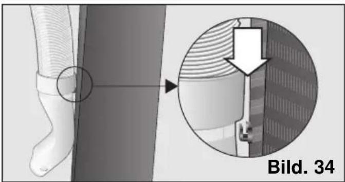
natural_image
Medical illustration showing a foot with a circular annotation and magnified view of internal tissue structure (no text or symbols)
- PAM0520 PAM0540 PAM0530
- Festinstallation
- Achtung!
- Environmental protection
- Important Information
- Your new appliance
- Requirements for use
- Instructions for Use
- Cleaning and Maintenance
- Things to check before calling the Technical Service
- Recommendations for the disposal of packaging
- Recommendations for the disposal of your old appliance
- Recommendations for saving energy
- Before connecting your appliance
- If there are children in the home
- Description of the appliance
- Transportation requirements
- Preparing the appliance
- Fitting the air expulsion tube and accessories onto the appliance
- Securing the diffusion duct onto the air expulsion tube
- Ways of releasing air outdoors Temporary installation
- Permanent installation
- Notes
- Cooling
- Warning!
- Dehumidification
- Air purification
- Note:
- Heating (only on PAM0530)
- Cleaning the appliance
- Cleaning and changing the purifying filters
- Fitting the purifying filter (double active)
- Note
- Storage requirements
- Prior to use at change of season
- General requirements for operation What to do if...
- Noise
- Perfectly normal noise
- Easy-to-solve noises
- Technical service / Warranty
- Technical service
- Warranty
- Sommaire
- Mode d'Emploi
- Conditions de transport
- Installation fixe
- Attention!
- Instalación fija
- ¡Atención!
- Instruções de Uso
- Instalação fixa
- Atenção!
- Vaste installatie
- Let op!
- Verwarming (alleen in model PAM0530
- Istruzioni d'uso
- Installazione fissa
- Attenzione!
- Så sparar Du energi
- Fast installation
- OBS!
Brand : BOSCH
Model : PAM 0540
Category : Air Conditioning