CMPNWIPCAM31 - Webcam KONIG - Free user manual and instructions
Find the device manual for free CMPNWIPCAM31 KONIG in PDF.

User questions about CMPNWIPCAM31 KONIG
0 question about this device. Answer the ones you know or ask your own.
Ask a new question about this device
Download the instructions for your Webcam in PDF format for free! Find your manual CMPNWIPCAM31 - KONIG and take your electronic device back in hand. On this page are published all the documents necessary for the use of your device. CMPNWIPCAM31 by KONIG.
USER MANUAL CMPNWIPCAM31 KONIG
IP Wireless Network Camera
MODE D'EMPLOI (p. 20)
MANUAL DE USO (p. 47)
Appearance and Interface
Notes:
- Power Indicator: It will turn RED if the equipment is powered on.
- Status Indicator: Slow flickering (once every 2 seconds) indicates that the device is searching for a network; flickering (once or twice per second) indicates that the wired network is connected; frequent flickering (2 to 3 times per second) indicates that the wireless network is connected.
Equipment Interface
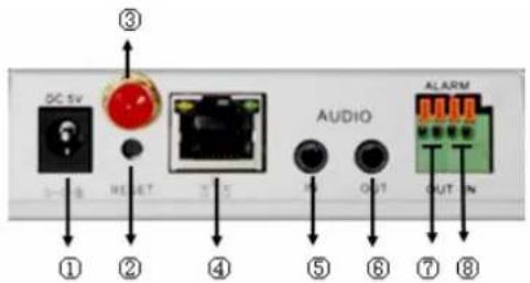
- Power Input Socket: Connects to a DC adapter, its output should be 5V power specification.
- RESET Button: If the RESET button is pressed and held for more than 10 seconds, the equipment will restart and recover to the default factory settings.
- WIFI Antenna Hole: Installs the WIFI antenna.
- RJ45 Ethernet Socket: The RJ45 Ethernet socket is 10/100M self-adjusting. The equipment can connect to all kinds of network equipment, such as hub, router, switch, etc.
NOTE: The factory setting IP is 192.168.0.178, the http port is 80, the username is admin, the password is 123456.
Audio Input Socket: The audio input socket is designed for connecting an external microphone. The built-in microphone will be invalid when the external microphone is plugged in.
Audio Output Socket: The audio output socket is for a line-out audio player, such as headphone, speaker, etc.
- Alarm Output Socket: The alarm output socket is connected to a relay in the IP camera. The IP camera will control the switch to trigger the alarm bell or buzzer to alarm. The relay is able to control the switch of an alarm whose voltage is no more than 36V and whose current is lower than 2 A. Please refer to Figure 2 for the connection of an external alarm.
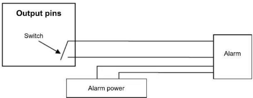
Figure 2
- Alarm Input Pin: Please refer to the schematic diagram in Figure 3 for how the external detector collects alarm information.
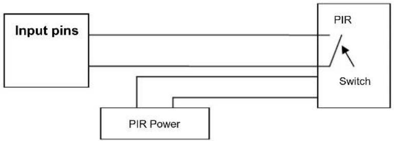
Figure 3
The detector should be a switched type (always on or always off). If the detector has detected smoke, or people or animals entering the area, the detector will switch on or switch off and it will send the external alarm signal to the IP camera.
Connecting to the Network
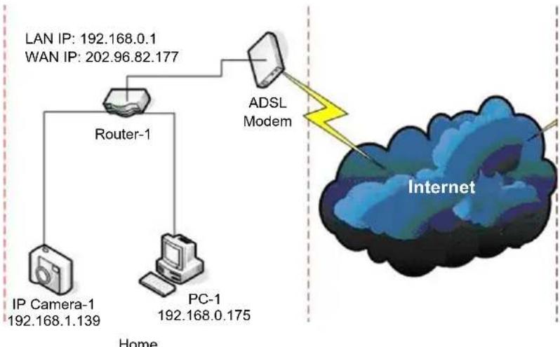
Figure 4
Connection Instructions
Before visiting the IP Camera, connect it to the network first, supply power to it, and check if the light of the RJ45 Socket is normal to make sure all of the communication links are fluent. The connection method is like that of Figure 4.
Setting the IP Address
The IP addresses of the IP Camera and PC should be at the same segment. The example in Figure 5.1 shows that IP Camera-1 can't be visited. Run BSearch_en.exe in the CD, click the Search button, and then select IP Camera-1 to reset the IP address, as shown in Figure 5.2.
Setup Instructions:
- Carefully check the "Local PC information" on the top left corner which lists the PC configuration. If there are several network adapters in the PC, please select the one you are using and make sure the IP address of the IP Camera is at the same segment of the PC.
-
Change the content of "IP config" on the right to make sure that the content is the same as "Local PC information". You only need to set the last section of the IP address, you can set it as 139 just like the example in Figure 5.2.
If you don't know how to fill out the contents of "IP config", you could also tick "Set IP automatically" to automatically get the IP address from the router. -
Type the user name and password into "Authentication" (By default, the user name is admin, password is 123456). Click "Update". The setting will take effect now. Select the device in the list box and click the "Browse" button, it will open the browser automatically and a window will pop up at the same time which requires you to enter the user name and password. Then you will see the home page of IP Camera-1, click "English" on the top right corner as in Figure 6 below. On the right corner of the interface, the user can choose the language.
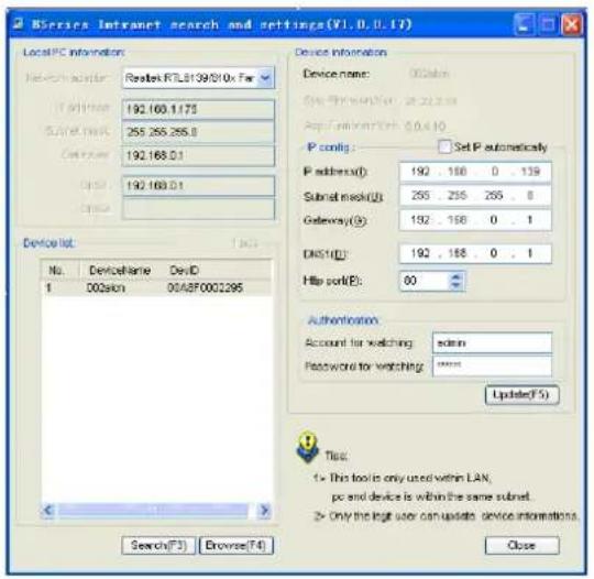
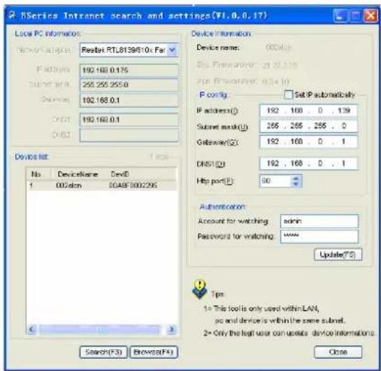

Figure 5.1 Figure 5.2
If you have firewall software on your PC, when you run BSearch_en.exe, a window may pop up asking if you want to block this program or not, then you should choose not to block.
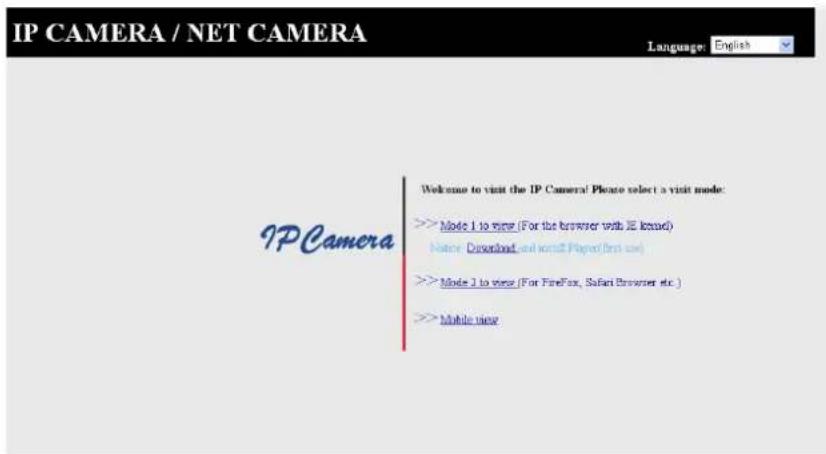
Figure 6
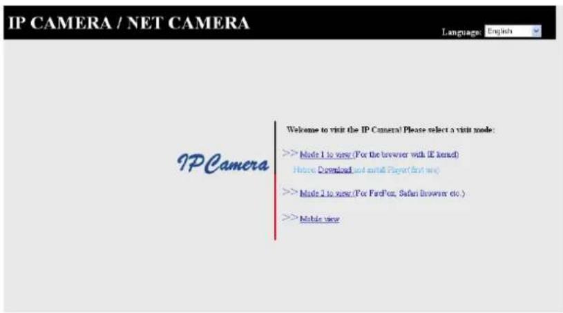
Visiting the IP Camera
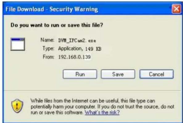
We suggest using IE kernel browser to view the video (it can provide more functions), but the user needs to install a player before viewing the video. Click the "download and install player (first use)" link, a dialogue box as in Figure 7 will pop-up, click Run, it will automatically download and install the player.

Figure 7
After installing the plug-ins, click the "Mode 1 to view" link in Figure 7 to view the video (video as in Figure 8).
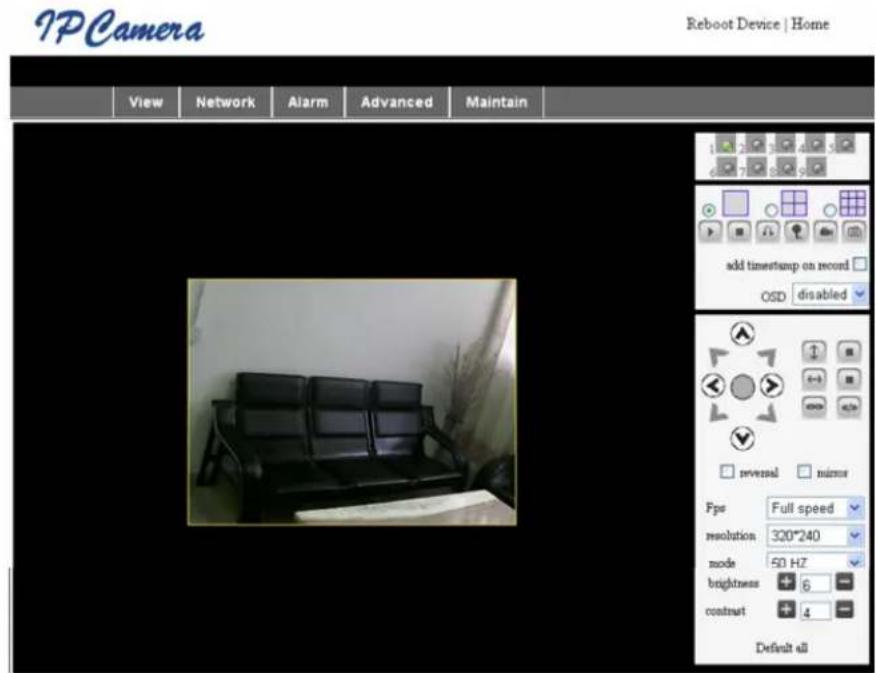
Figure 8
1. Menu Column
There are 2 kinds of menus, one is the main menu, and the other is the submenu. The main menu is at the top of the interface, including View, Network, Alarm, Advanced, Maintain, the submenu is on the right of the interface.
Video Display Area
The video display area is dependent on the resolution, the higher the resolution, the larger the display. Double click the left mouse button in the video display area and it will show the full screen, double click it again and it will go back to the original size. Double click the right mouse button in the video display area and it will show the green icon, click the left mouse button and Pan/Tilt will remote according to the arrow signs.
2. Status Display Area
At the upper right corner is the status display area which shows the device's status:
- If not connected, the button is gray
- If connected, the button is green
- If incorrectly connected, the button is yellow
- If there is an alarm, the button is red
3. Multi Channel Display Area
If the user adds multi channels (refer to 7.3.2), it will shift to 4-Ch, 9-CH and will automatically show other devices. On the display area, if the image is chosen, you can play, stop, record, control Pan/Tilt and perform other operations.

These buttons stand for start video, stop, monitor, talk, record and snapshot.
Click a button to choose a function.
4. PTZ and Video Control
In the Pan/Tilt control area, the user can control the position according to the arrow sign: up, down, left, right, middle, horizontal cruise, vertical cruise, stop, etc.

stands for open IO output and closed IO output.
The user can also set the device frame rate, resolution, brightness, contrast and other parameters.
Visiting the IP Camera from WAN
Port forwarding
To view the camera over the Internet, you need to forward a port in your router to the IP of the camera. To open a port in your router and make the camera accessible over the internet, read the part in the manual of your router that contains "port forwarding". Figure 9 is an example.
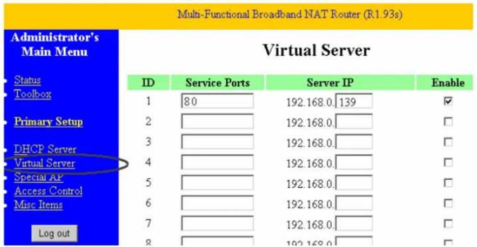
Figure 9
Other Settings
WIFI Setting
Enter the Wireless LAN Setting as shown in Figure 10 below, click the "Search" button several times and it will show you the wireless networks detected in the Wireless Network List column. Select one of them and tick "Using Wireless Lan", then the relevant data of the selected wireless network will be shown in the succeeding blanks. Enter the password and click "Set", then the WIFI setting is finished.
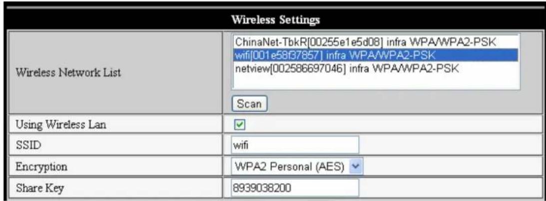
Figure 10
Note: When the device is connected to both WIFI and wired, after it starts up, it will connect first to the wired network, if it can't connect, then it will connect to the WIFI. The IP address and port are the same for either wireless or wired network.
Advanced User Settings
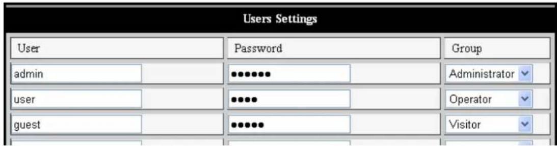
Figure 11
There are three levels of authority; they are Administrator/Operator/Visitor. The Administrator has the highest authority, it can make any change to the settings. The Operator account can only operate the IP camera, it cannot make changes to the settings, please refer to Figure 11. The Visitor account can only watch the video, it cannot operate the IP camera. By default, the administrator's user name is admin, password is 123456.
Other settings
You can choose open or closed indicator LED. If the PTZ centre is set to "Yes" on startup, when the device is started up, Pan/Tilt will move to the centre and then stop. You can also set the horizontal patrol rounds and vertical patrol rounds, when you click patrol on the "view" interface, it will round according to your rounds setup. You can also set the PTZ rate, 0 means fastest.
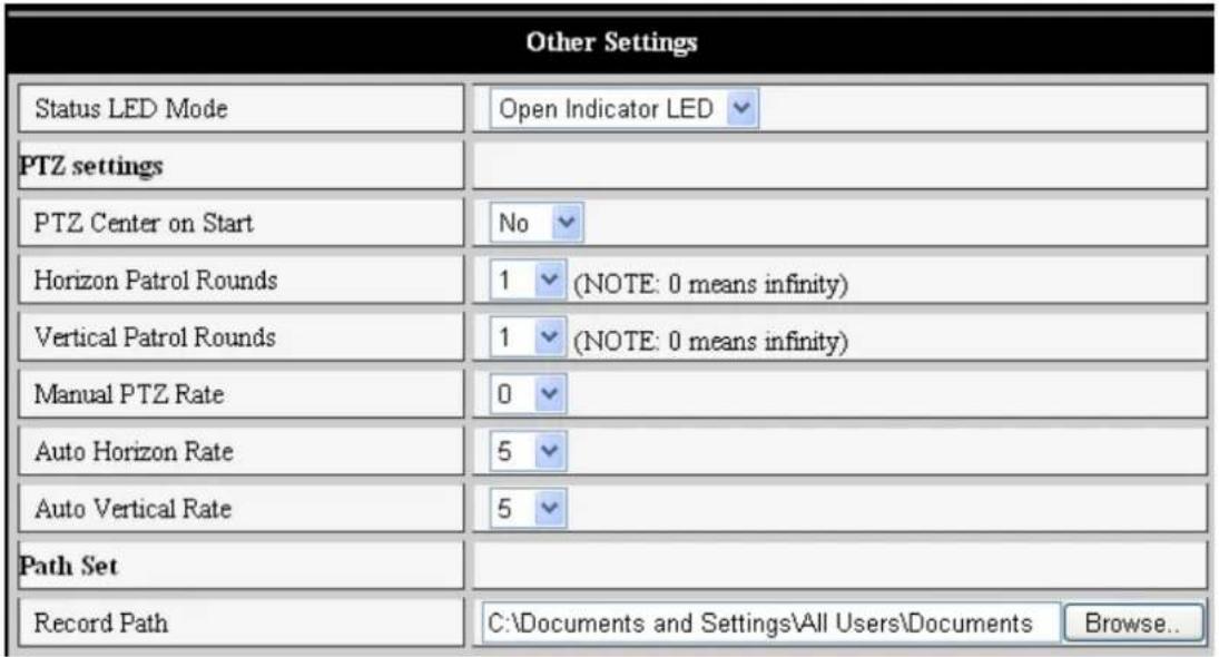
Figure 12
Maintenance
Device Information
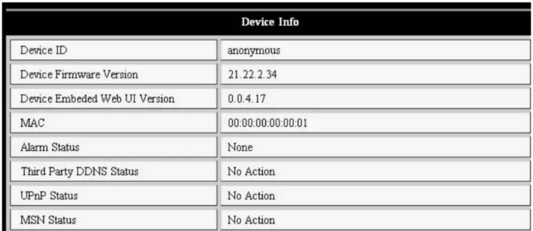
Figure 13
Time Setting
If the device is connected to the Internet, enable the NTP server to correct the time and select the right time zone, or use the PC time to correct the device time.
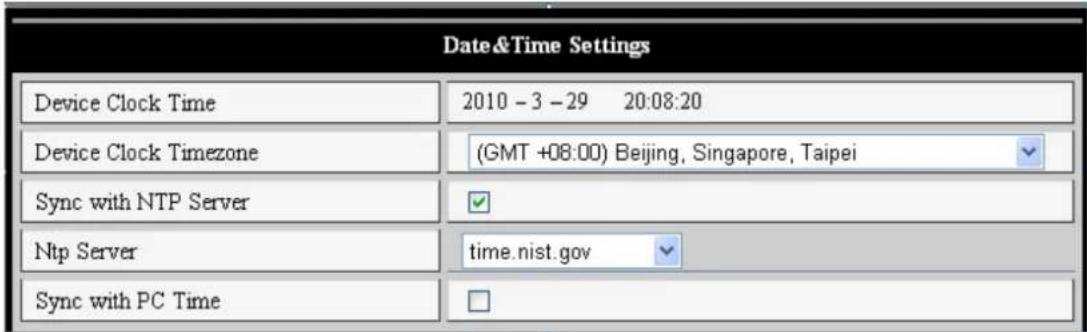
Figure 14
Firmware Upgrade
The device runs 2 kinds of programs, one is a system firmware, the other is an application firmware. They could be upgraded separately.
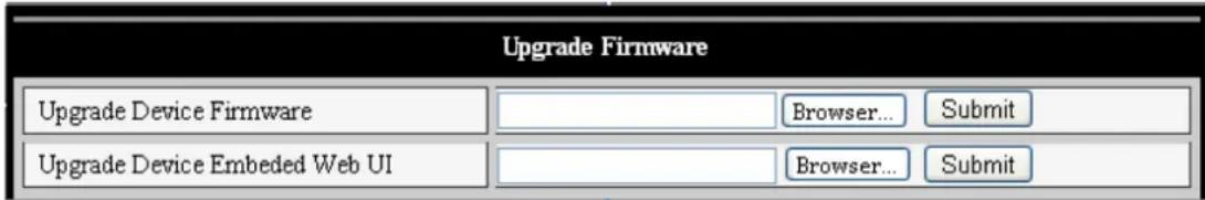
Figure 15
Click "Restore Factory Default", a dialogue will pop up to confirm if you really want to restore the factory default. After confirmation, the system will restore the factory default and reboot.
User Browsing Log
After entering the log interface, you could view who visited the device and when.
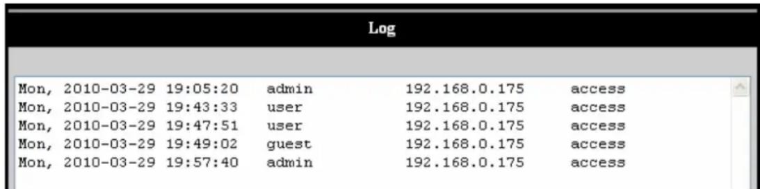
Figure 16
FAQ
1. Mismatched power adapter will damage the equipment or power adapter
When plugging in the power adapter, carefully check the voltage, it should be a 5 V adapter for this equipment.
2. Slow browsing speed
This equipment uses MJEPG compression format, it needs a large network bandwidth, a narrow bandwidth will affect the browsing speed. The typical bandwidth used is as follows:
640x480@10fps: 4.0 Megabits ~ 5.0 Megabits
320x240@30fps: 1.2 Megabits ~ 1.6 Megabits
3. Can't find equipment via search software after connecting to LAN
Make sure the equipment and PC are in the same LAN; if a firewall software is installed, please close it and try again.
4. Equipment can be found via search software, but can't be visited
If the IP addresses of the IP camera and PC are not in the same network segment, you should change them to the same network segment before visiting. The network segment is the first three numbers of the IP address. If the IP address of the PC is 192.168.0.100, it can only visit equipment whose IP address is between 192.168.0.1~192.168.0.255.
5. Can't visit the equipment via Internet
Please refer to:
Chapter 4 (Figure 2) to check if the internet connection is correct;
Chapter 5 to check if you can visit via LAN;
Chapter 6 to check if the port forwarding is correct and if the router setting forbids this equipment to send data to the internet.
6. Can visit via public IP address, but can't visit via manufacturer's domain name
Make sure the DNS setting is the same as your PC, as in Figure 17 below. In the search tool, the DNS 1 and DNS 2 on both sides should be the same.
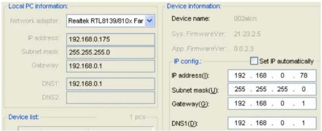
Figure 17
Safety precautions:
This product should ONLY be opened by an authorized technician when service is required. Disconnect the product from mains and other equipment if a problem should occur. Do not expose the product to water or moisture.
Maintenance:
Clean only with a dry cloth. Do not use cleaning solvents or abrasives.
Warranty:
No guarantee or liability can be accepted for any changes and modifications of the product or damage caused due to incorrect use of this product.
General:
Designs and specifications are subject to change without notice.
All logos brands and product names are trademarks or registered trademarks of their respective holders and are hereby recognized as such.
Keep this manual and packaging for future reference.
Attention:

This product is marked with this symbol. It means that used electrical and electronic products should not be mixed with general household waste. There is a separate collections system for these products.
DEUTSCH
640x480@10 fps: 4,0 Megabit ~ 5,0 Megabit
320x240@30 fps: 1,2 Megabit ~ 1,6 Megabit
Er zijn drie gezagsniveauaus;这一切 is the most exciting and most exciting of all. Er is the best way to get a good look at the new technology. It's the best way to see how it works. The first thing you'll learn about this technology is how to use it. It's not just about how to use it, but also about how to understand it.
Overige instellingen
640x480@10fps: 4.0 Megabit ~ 5.0 Megabit
320x240@30fps: 1,2 Megabit ~ 1,6 Megabit
640x480 a 10fps: 4,0 Megabits ~ 5,0 Megabits
320x240 a 30fps: 1,2 Megabits ~ 1,6 Megabits
| Device Clock Time | 2010 - 3 - 29 20:08:20 |
| Device Clock TImezone | (GMT +08:00) Beijing, Singapore, Taipei |
| Sync with NTP Server | ✓ |
| Ntp Server | time.nist.gov |
| Sync with PC Time | □ |
Firmware-päivitys
| Upgrade Firmware | ||
| Upgrade Device Firmware | Browser... Submit | |
| Upgrade Device Embedded Web UI | Browser... Submit | |
| Device Clock Time | 2010-3-29 20:08:20 |
| Device Clock TImezone | (GMT+08:00) Beijing, Singapore, Taipei |
| Sync with NTP Server | ✓ |
| Ntp Server | time.nist.gov |
| Sync with PC Time | □ |
Upgrade firmware
| Upgrade Firmware | ||
| Upgrade Device Firmware | Browser... Submit | |
| Upgrade Device Embedded Web UI | Browser... Submit | |
640x480@10 fps: 4,0 Megabiti ~ 5,0 Megabiti
320x240@30 fps: 1,2 Megabiti ~ 1,6 Megabiti

Eikova 5.1 Eikova 5.2
Av exTe EYkataoTnei loyiauKO teixouc TPOaTaoiac OTOV UTOAOYIOIgOAC,OTAV AVOiyETo apxio BSearch_en.exe, eupavizetai eva npapato nou aoc zntaei av theleve aATOKeoge auto to Tpoypaumn oxi. Oa PPTEIE va etilegeve va mnu ATOKeiotei auto to Tpoypauma.
Eikóva 6
Aeitoupyia tns kaepaIp
Zuviooue Tn xpnoTou TPOpypaMaTOc TEPiynoNc IEC kernel yia Tnv Epuavion Tou BivTeo (TAPExI TEPIOOtepeC AIToupyies), aAa o xpnoTnc TpETe i va EykataoTneEva TPOpyma avattapaywyns TPIV TIV TPOBoLn Tou BivTeo. KAVTE KIAK OTov ouvdeoOo H KAI EYkataaToaon TPOpypaMaTOc avattapaywyns (Tpwn xpno) (download and install player (first use)). Oa EpuavioteEv a PAlio dialoyou otwoc otnv
Eikova 7, kai a kavete klik oTo KoumuTi «Run». Oa Tpaayatotoin autouatn kai EykataoTou Tpoypapmuos avattapaywyns.
Eikova 7
Metayevkataoan twv npooetuw, kavte kik otov ouvdeo mode 1 to view 出 ony Eikova 7 yia va eepavioeTo bivteo (bivteo oTWC stny Eikova 8).

Eikova 8
1. Στήλη μενου
640x480@10fps: 4,0 Megabits ~ 5,0 Megabits
320x240@30fps: 1,2 Megabits ~ 1,6 Megabits
3. tov eioiao muo meow avaizntnoi loyioikou eta n ouvdeon oTO LAN
640x480@10fps: 4,0 Megabits ~ 5,0 Megabits
320x240@30fps: 1,2 Megabits ~ 1,6 Megabits
3. Kan/DDyre viasgnings software after tilutng til LAN
Still inn IP-adressen
640x480@10 fps: 4,0 Megabits ~ 5,0 Megabits
320x240@30 fps: 1,2 Megabits ~ 1,6 Megabits
Description: IP Wireless Network Camera