GCM 12 GDL - Saw BOSCH - Free user manual and instructions
Find the device manual for free GCM 12 GDL BOSCH in PDF.
Download the instructions for your Saw in PDF format for free! Find your manual GCM 12 GDL - BOSCH and take your electronic device back in hand. On this page are published all the documents necessary for the use of your device. GCM 12 GDL by BOSCH.
USER MANUAL GCM 12 GDL BOSCH
2. Swivel the glide arm slightly to the
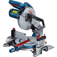
using the rotary knob Setting the bevel angle ranges using the rotary knob: Saw blade inclination to the left (45° to 0°) Saw blade inclination to the right (0° to 45°) Entire swivel range of the glide arm (– 47° to +47°) English | 33 Bosch Power Tools 1 609 92A 4CT | (20.07.2018)34 | English 1 609 92A 4CT | (20.07.2018) Bosch Power Tools Product description and specifications Read all the safety and general instructions. Failure to observe the safety and general in- structions may result in electric shock, fire and/or serious injury. Please observe the illustrations at the beginning of this oper- ating manual. Intended use The power tool is intended as a stationary machine for mak- ing straight cuts in wood with and against the grain. It is pos- sible to cut mitre angles of -52° to +60° and bevel angles of 47° (to the left) to 47° (to the right). The power tool is designed with sufficient capacity for saw- ing hardwood and softwood as well as chipboard and fibre- board. When using appropriate saw blades, sawing aluminium pro- files and plastic is also possible. Product features The numbering of the product features refers to the diagram of the power tool on the graphics page. (1) Handle (2) Lock-off switch for on/off switch (3) Protective guard (4) Retracting blade guard (5) Adjustable fence (6) Fence (7) Saw table extension (8) Mounting holes (9) Insert plate (10) Locking clamp (11) Locking knob for various mitre angles (12) Mitre presetting lever (13) Clamping handle for various bevel angles (14) Spacer
(37) Scale for mitre angle (38) Saw table (39) Rotary knob for adjusting the bevel angle range (40) Saw blade (41) Laser beam outlet aperture (42) Locking screw for the linkage of the retracting blade guard (43) Linkage of the retracting blade guard (44) Front fastening screw (cover plate/retracting blade guard) (45) Rear fastening screw (cover plate/retracting blade guard) (46) Cover plate (47) Spindle lock (48) Hex socket screw for mounting of saw blade (49) Clamping flange (50) Interior clamping flange (51) Clamping lever of the saw table extension (52) Locking screw for the adjustable fence (53) Damper (54) Set screws for damping (55) Holes for screw clamp (56) Wing bolt (57) Threaded rod (58) Angle indicator for mitre angles (59) On/off switch (60) On/off switch for laser (cutting line indication) (61) Screws for insert plate (62) Clamping screw for length stop
(63) Screw for laser protection cap (64) Set screw for positioning the laser (flush levelling) (65) Fastening screw for laser mounting plate (66) Fastening screw for laser housing (67) / (68) / (69) Set screws for 0° basic setting (bevel angle)(70) Set screw for 45° basic setting (left-hand bevel angle) (71) Set screw for 45° basic setting (right-hand bevel angle) (72) Set screws for mitre angle scale (73) Screw for mitre angle indicator (74) Set screw for adjusting the clamping force of the clamping handle for any bevel angle (75) Hook-and-loop strap
Accessories shown or described are not included with the product as standard. You can find the complete selection of accessories in our accessories range. Technical Data Sliding mitre saw GCM 12 GDL GCM 12 GDL GCM 12 GDL Article number 3 601 M23 601 3 601 M23 631 3 601 M23 671 3 601 M23 661 3 601 M23 691 3 601 M23 6P1 Rated power input W 2000 1500 1800 Rated voltage V 230–240 110 220–240 Frequency Hz 50/60 50/60 50/60 No-load speed rpm 4000 4000 4000 Starting current limitation ● – ● Laser type nm 650 650 650 mW < 1 < 1 < 1 Laser class 1 1 1 Weight according to EPTA-Procedure 01:2014 kg 32.1 32.1 32.1 Protection class / II / II / II Dimensions of suitable saw blades Saw blade diameter mm 305 305 305 Base blade thickness mm 1.7−2.6 1.7−2.6 1.7−2.6 Max. cutting width mm 3.2 3.2 3.2 Hole diameter mm 30 30 30 Permitted Workpiece Dimensions (maximum/minimum): (see "Permissible workpiece dimensions", page40) Noise information Noise emission values determined according to EN 62841-3-9. Typically, the A-weighted noise level of the power tool is: Sound pressure level 93dB(A); sound power level 106dB(A). Uncertainty K=3dB. Wear hearing protection The noise emission value given in these instructions has been measured in accordance with a standardised measur- ing procedure and may be used to compare power tools. It may also be used for a preliminary estimation of noise emis- sions. The noise emission value given represents the main applica- tions of the power tool. However, if the power tool is used for other applications, with different application tools or is poorly maintained, the noise emission value may differ. This may significantly increase noise emissions over the total working period. To estimate noise emissions accurately, the times when the tool is switched off, or when it is running but not actually be- ing used, should also be taken into account. This may signi- ficantly reduce noise emissions over the total working period. Assembly u Avoid starting the power tool unintentionally. The mains plug must not be connected to the power supply during assembly or when carrying out any kind of work on the power tool. Items Included Carefully remove all parts included in the delivery from their packaging. Remove all packing material from the power tool and the ac- cessories provided. Check to ensure that all the parts listed below have been supplied before using the power tool for the first time: – Sliding mitre saw with mounted saw blade (40) – Locking knob (11) – Hex key (17) English | 35 Bosch Power Tools 1 609 92A 4CT | (20.07.2018)36 | English 1 609 92A 4CT | (20.07.2018) Bosch Power Tools – Hex key (18) – Screw clamp (19) Note: Check the power tool for possible damage. Before continuing to use the power tool, carefully check that all protective devices or slightly damaged parts are working perfectly and according to specifications. Check that the moving parts are working perfectly and without jamming; check whether any parts are damaged. All parts must be fit- ted correctly and all the conditions necessary to ensure smooth operation must be met. If the protective devices or any parts become damaged, you must have them repaired or replaced by an authorised ser- vice centre immediately. Extra tools required (not included in the delivery): – Cross-headed screwdriver – Open-ended spanner (size: 8 mm) – Ring spanner, open-ended spanner or socket spanner (sizes: 10 mm and 17 mm) Fitting the locking knob (see figure a) – Screw the locking knob (11) into the corresponding hole above the lever (12). u Always tighten the locking knob (11) firmly before sawing. Otherwise the saw blade can become wedged in the workpiece. Stationary or flexible mounting u To ensure safe handling, the power tool must be mounted on a flat, stable work surface (e.g. work bench) before use. Mounting on a Work Surface (see figure b1) – Use suitable screw fasteners to secure the power tool to the work surface. Use the holes (8) to do this.
– Firmly clamp the base of the power tool to the work sur- face with commercially available screw clamps. Mounting on a Bosch Saw Stand (GTA 2500 W, GTA 3700, GTA 3800) (see figure b2) Thanks to their height-adjustable legs, Bosch GTA saw stands provide firm support for the power tool on any sur- face. The workpiece supports on the saw stands are used to support long workpieces. u Read all the warnings and instructions included with the saw stand. Failure to observe the warnings and fol- low instructions may result in electric shock, fire and/or serious injury. u Assemble the saw stand properly before mounting the power tool. Correct assembly is important to prevent the risk of collapsing. – Mount the power tool on the saw stand in the transport position. Dust/chip extraction The dust from materials such as lead paint, some types of wood, minerals and metal can be harmful to human health. Touching or breathing in this dust can trigger allergic reac- tions and/or cause respiratory illnesses in the user or in people in the near vicinity. Certain dusts, such as oak or beech dust, are classified as carcinogenic, especially in conjunction with wood treatment additives (chromate, wood preservative). Materials contain- ing asbestos may only be machined by specialists. – Use a dust extraction system that is suitable for the ma- terial wherever possible. – Provide good ventilation at the workplace. – It is advisable to wear a P2 filter class breathing mask. The regulations on the material being machined that apply in the country of use must be observed. u Avoid dust accumulation at the workplace. Dust can easily ignite. The dust/chip extraction system can be blocked by dust, chips or fragments of the workpiece. – Switch the power tool off and pull the mains plug out of the socket. – Wait until the saw blade has come to a complete stop. – Determine the cause of the blockage and eliminate it. External Dust Extraction You can also attach a dust extraction hose (35 mm dia- meter) to the dust extraction adapter (24) for extraction. – Insert the dust extraction hose into the dust extraction adapter (24). The dust extractor must be suitable for the material being worked. When extracting dry dust that is especially detrimental to health or carcinogenic, use a special dust extractor. Cleaning the dust extraction adapter To ensure optimum extraction, the dust extraction adapter (24) must be cleaned regularly. – Pull the dust extraction adapter (24) off the chip ejector (23) with a twisting motion. – Remove workpiece fragments and chippings. – Reattach the dust extraction adapter to the chip ejector with a twisting motion until it engages above the chip ejector holding ring. Changing the Saw Blade (see figures c1−c4) u Pull the plug out of the socket before carrying out any work on the power tool. u Wear protective gloves when fitting the saw blade. There is a risk of injury when touching the saw blade. Only use saw blades the maximum permitted speed of which is higher than the no-load speed of the power tool. Only use saw blades that match the specifications given in this operating manual and that have been tested and marked in accordance with EN847-1. Only use saw blades that are recommended by the power tool manufacturer and are suitable for using on the material you want to saw. This will prevent the saw teeth overheating when sawing.Removing the Saw Blade – Bring the power tool into the work position. – Unscrew the locking screw (42) by hand until the linkage (43) can hang down freely. – Loosen the fastening screw (44) (by approx. two turns) using the hex key (4 mm) (17). Do not unscrew the screw completely. – Loosen the fastening screw (45) (by approx. six turns) using the hex key (4 mm) (17). Do not unscrew the screw completely. – Pull the cover plate (46) forwards and downwards away from the fastening screw (45). – Swivel the retracting blade guard (4) to the back and hold the retracting blade guard in this position. – Hang the linkage (43) over the fastening screw (45) using a hole. This will hold the retracting blade guard open. – Turn the hex socket screw (48) with the hex key (6 mm) (17) and at the same time press the spindle lock (47) un- til it engages. – Press and hold the spindle lock (47) and loosen the hex socket screw (48) by turning it clockwise (left-hand thread). – Remove the clamping flange (49). – Remove the saw blade (40). Fitting the saw blade If required, clean all the parts you want to fit before installing them. – Place the new saw blade onto the interior clamping flange (50). u When fitting the saw blade, make sure that the cutting direction of the teeth (arrow direction on the saw blade) matches the direction of the arrow on the pro- tective guard. – Fit the clamping flange (49) and the hex socket screw (48). Press the spindle lock (47) until it engages and tighten the hex socket screw by turning it anticlockwise. – Release the linkage (43) from the fastening screw (45) and guide the retracting blade guard (4) back down. – Slide the cover plate (46) back under the fastening screw (45). – Retighten the fastening screws (45) and (44). – Slide the linkage (43) into its original position and retighten the locking screw (42) by hand. Operation u Pull the plug out of the socket before carrying out any work on the power tool. Transport Safety Lock (see figure A) The transport safety lock (31) makes it easier to handle the power tool when transporting it to various working locations. Unlocking the Power Tool (Work Position) – Press the glide arm (28) down slightly by the handle (1) to release the transport safety lock (31). – Pull the transport safety lock (31) all the way out. – Slowly guide the glide arm (28) upwards. Locking the Power Tool (Transport Position) – Slide the glide arm (28) all the way back and secure it in this position (see "Securing the Glide Arm (see figure B2)", page37). – Guide the glide arm downwards until you can press the transport safety lock (31) all the way in. Further information: (see "Transport (see figure Z)", page43) Locking the Glide Arm The glide mechanism of the glide arm (28) can be locked with the clamping lever (25). The glide arm can be placed in two positions: – Glide arm pushed all the way back (for cross cuts) – Glide arm pulled all the way forward (for a compact trans- port position) Unlocking the Glide Arm (see figure B1) After unlocking the glide arm (28), the whole gliding mech- anism is ready for operation. – Press the clamping lever (25) all the way down. – The clamping wedge of the clamping lever releases the two articulated parts at the bottom of the glide arm. Securing the Glide Arm (see figure B2) Glide arm pushed all the way back: – Push the glide arm (28) all the way back. – The two articulated parts at the top of the glide arm are now upright and closed. – Pull the clamping lever (25) upwards until the clamping wedge is positioned between the two articulated parts at the bottom of the glide arm. – This locks the glide arm (28), which is pushed all the way back. Glide arm pulled all the way forward: – Pull the glide arm (28) all the way forward. – The glide mechanism is now completely extended. – Pull the clamping lever (25) upwards until the clamping wedge is positioned between the two articulated parts at the bottom of the glide arm. – This locks the glide arm (28), which is pulled all the way forward. Preparing for Operation Extending the Saw Table (see figure C) The free end of long workpieces must have something placed underneath it or be supported. The saw table can be extended left and right using the saw table extensions (7). – Push the clamping lever (51) inwards. English | 37 Bosch Power Tools 1 609 92A 4CT | (20.07.2018)38 | English 1 609 92A 4CT | (20.07.2018) Bosch Power Tools – Pull out the saw table extension (7) to the required length (maximum 250 mm). – To lock the saw table extension in place, push the clamp- ing lever (51) back out. Moving the fence (see figures D–E) When sawing mitre and/or bevel angles, you have to pull the left-hand or right-hand adjustable fence (5) outwards depending on the cutting direction, or remove it completely. Bevel angle Mitre angle 0°–47° (left) ≤ 44° (right/left) – Loosen the locking screw (52). – Pull the left-hand adjustable fence (5) all the way out. 0°–47° (left) ≥ 45° (right/left) – Loosen the locking screw (52). – Pull the left-hand adjustable fence (5) all the way out. – Lift the adjustable fence upwards and out of the way. – Remove the locking screw (52). 0°– 47° (right) ≤ 44° (right/left) – Loosen the locking screw (52). – Pull the right-hand adjustable fence (5) all the way out. – Lift the adjustable fence upwards and out of the way. 0°– 47° (right) ≥ 45° (right/left) Adjusting the Damping of the Glide Arm (see figure F) The glide mechanism of the glide arm (28) is preset at the factory and is not damped when the power tool is delivered. The damping of the glide mechanism can be adjusted using the damper (53): Hard – for more controlled work movements; Soft – for fast saw cuts. – For softer damping, loosen the two set screws (54) using the hex key (4 mm) (17) – or – tighten the two set screws (54) for harder damping. Clamping the Workpiece (see figure G) To ensure maximum safety while working, the workpiece must always be firmly clamped. Do not saw workpieces that are too small to clamp firmly. – Press the workpiece firmly against the fence (6). – Insert the supplied screw clamp (19) into one of the holes (55) intended for this purpose. – Loosen the wing bolt (56) and adapt the screw clamp to the workpiece. Tighten the wing bolt again. – Firmly clamp the workpiece by turning the threaded rod (57). Adjusting the horizontal mitre angle To ensure precise cuts, the basic settings of the power tool must be checked and adjusted as necessary after intensive use (see "Checking and Adjusting the Basic Settings", page42). u Always tighten the locking knob (11) firmly before sawing. Otherwise the saw blade can become wedged in the workpiece. Setting Standard Mitre Angles (see figure H) For quick and precise setting of commonly used mitre angles, detents (15) are provided on the saw table: Leftward Rightward
45°; 31.6°; 22.5°; 15° 15°; 22.5°; 31.6°; 45°; 60° – Loosen the locking knob (11) if it is tightened. – Pull the lever (12) and rotate the saw table (38) left or right to the required detent. – Release the lever again. The lever must be felt to engage in the detent. – Retighten the locking knob (11). Setting Any Mitre Angle (see figure I) The mitre angle can be set between 52° (left side) and 60° (right side). – Loosen the locking knob (11) if it is tightened. – Pull the lever (12) and at the same time press the locking clamp (10) until this clicks into the slot provided for it. This means the saw table can now move freely. – Turn the saw table (38) left or right by the locking knob until the angle indicator (58) shows the required mitre angle. – Retighten the locking knob (11). – To loosen the lever (12) again (for setting standard mitre angles), pull the lever upwards. The locking clamp (10) springs back into its original posi- tion and the lever (12) can click back into the detents (15). Adjusting vertical mitre angles To ensure precise cuts, the basic settings of the power tool must be checked and adjusted as necessary after intensiveuse (see "Checking and Adjusting the Basic Settings", page42). The bevel angle can be set between 47° (left side) and 47° (right side). For quick and precise setting of frequently used bevel angles, stops have been provided for the angles 0°, 22.5°, 45° and 47°. Setting the left-hand bevel angle range (45° to 0°) – Pull the left-hand adjustable fence (5) all the way out (see "Moving the fence", page38). – Loosen the clamping handle (13). – Use the handle (1) to swivel the glide arm (28) to the left until the angle indicator (33) shows the required bevel angle. – Hold the glide arm (28) in this position and retighten the clamping handle (13). The clamping force of the clamping handle must hold the glide arm securely in place at any bevel angle. Setting the Right-hand Bevel Angle Range (0° to 45°) (see figure J) – Pull the right-hand adjustable fence (5)all the way out (see "Moving the fence", page38). – Loosen the clamping handle (13). – Use the handle (1) to tilt the glide arm (28) slightly to the left from the 0° position and turn the rotary knob (39) un- til the required bevel angle range is shown. – Use the handle (1) to swivel the glide arm (28) to the right until the angle indicator (21) shows the required bevel angle. – Hold the glide arm (28) in this position and retighten the clamping handle (13). The clamping force of the clamping handle must hold the glide arm securely in place at any bevel angle. Setting the Standard 0° bevel angle To enable the standard 0° bevel angle to be reset easily, the rotary knob (39) engages in the left- hand bevel angle range. – Swivel the glide arm (28) from the right to the 0° position. Setting the entire bevel angle range (–47° to +47°) – Pull both adjustable fences (5) all the way out (see "Mov- ing the fence", page38). – Loosen the clamping handle (13). – Use the handle (1) to tilt the glide arm (28) slightly to the left from the 0° position and turn the rotary knob (39) un- til the required bevel angle range is shown. – Use the handle (1) to swivel the glide arm (28) to the left or right until the angle indicator (33) or (21) shows the required bevel angle. – Hold the glide arm (28) in this position and retighten the clamping handle (13). The clamping force of the clamping handle must hold the glide arm securely in place at any bevel angle. Setting the Standard 22.5° Bevel Angle (see figure K) Pull the adjustment knob (34) all the way out and turn it 90°. Then use the handle (1) to swivel the glide arm (28) until you hear the glide arm engage. Start-up u Pay attention to the mains voltage. The voltage of the power source must match the voltage specified on the rating plate of the power tool. u Products that are only sold in AUS and NZ: Use a resid- ual current device (RCD) with a nominal residual current of 30 mA or less. Switching On (see figure L) – To start the power tool, first slide the lock-off switch (2) to the middle and then press and hold the on/off switch (59). Note: For safety reasons, the on/off switch (59) cannot be locked; it must remain pressed during the entire operation. Switching off – To switch off, release the on/off switch (59). Starting current limitation The electronic starting current limitation feature restricts the power of the power tool when it is switched on and enables operation using a 16 A fuse. Note: If the power tool runs at full speed immediately after being switched on, this means that the starting current limit- ation has failed. The power tool must be sent to the after- sales service without delay. For addresses, see: (see "After- sales service and advice on using products", page44). Practical advice General sawing instructions u Always tighten the locking knob (11) and the clamp- ing handle (13) firmly before sawing. Otherwise the saw blade can become wedged in the workpiece. u For all cuts, it must first be ensured that the saw blade at no time can come in contact with the fence, screw clamps or other machine parts. Remove any mounted auxiliary stops or adjust them accordingly. Protect the saw blade against impact and shock. Do not sub- ject the saw blade to lateral pressure. Do not saw warped/bent workpieces. The workpiece must always have a straight edge to face against the fence. English | 39 Bosch Power Tools 1 609 92A 4CT | (20.07.2018)40 | English 1 609 92A 4CT | (20.07.2018) Bosch Power Tools The free end of long and heavy workpieces must have some- thing placed underneath it or be supported. Make sure that the retracting blade guard operates properly and that it can move freely. The retracting blade guard must open when the glide arm is guided downward. When the glide arm is guided upward, the retracting blade guard must close again over the saw blade and lock in the uppermost po- sition of the tool arm. Marking the cutting line (see figure M) Two laser beams indicate the cutting width of the saw blade. This allows for exact positioning of the workpiece for sawing, without having to open the retracting blade guard. – Switch on the laser beams with the switch (60). – Position your mark on the workpiece between the two laser lines. Note: Before sawing, check if the cutting width is still indic- ated correctly (see "Adjusting the Laser", page41). Vibra- tions during intensive use, for example, can cause the laser beams to become misaligned. Position of the Operator (see figure N) u Do not stand in line with the saw blade in front of the power tool. Always stand to the side of the saw blade. This protects your body against possible kickback. – Keep hands, fingers and arms away from the rotating saw blade. – Do not reach one arm across the other when in front of the glide arm (28). Replacing the Insert Plates (see figure O) The red insert plates (9) can become worn after prolonged use of the power tool. Replace defective insert plates. – Bring the power tool into the work position. – Loosen the screws (61) using the hex key (4 mm) (17) and remove the old insert plates. – Insert the new right-hand insert plate. – Screw the insert plate as far as possible to the right with the screws (61) so that the saw blade does not come into contact with the insert plate over the entire length of the possible slide motion. – Repeat the work steps in the same manner for the left- hand insert plate. Permissible workpiece dimensions Maximum workpiece dimensions: Mitre angle Bevel angle Height x width [mm] Workpiece against fence Workpiece against spacer (accessory) 0° 0° 104 x 335 110 x 240 45° 0° 104 x 240 110 x 110 0° 45° (left) 50 x 335 50 x 295 0° 45° (right) 40 x 335 40 x 295 45° 45° (left) 50 x 240 50 x 200 45° 45° (right) 40 x 240 40 x 200 Minimum workpiece dimensions (= all workpieces that can be secured left or right of the saw blade using the supplied screw clamps (19)): 160 x 335 mm (length x width) Maximum cutting depth (0°/0°): 104 mm Sawing u Always tighten the locking knob (11) and the clamp- ing handle (13) firmly before sawing. Otherwise the saw blade can become wedged in the workpiece. Sawing without Slide Movement (cutting off) (see figure
– Push the glide arm (28) all the way back and secure it in this position (see "Securing the Glide Arm (see figure B2)", page37). Make sure that the depth stop (30) is pressed all the way in and that the adjusting screw (29) fits through the re- cess without touching the depth stop when moving the glide arm. – Firmly clamp the workpiece as appropriate for its dimen- sions. – Set the desired mitre and/or bevel angle if required. – Switch the power tool on (see "Switching On (see figure L)", page39). – Slowly guide the glide arm (28) downwards using the handle (1). – Saw through the workpiece applying uniform feed. – Switch off the power tool and wait until the saw blade has come to a complete stop. – Slowly guide the glide arm (28) upwards. Sawing with Slide Movement (see figure Q) u Maintain a firm grip on the handle before switching the power tool on and during the entire sawing pro- cess. Ensure that the movement of the glide arm is controlled during sawing. The glide arm is very easy to move and a moment of inattention could result in serious injury.– Unlocking the glide arm(28) (see "Unlocking the Glide Arm (see figure B1)", page37). Check whether the complete glide mechanism is ready to be used by sliding the glide arm (28) back and forth. – Firmly clamp the workpiece as appropriate for its dimen- sions. – Set the desired mitre and/or bevel angle if required. – Pull the glide arm (28) away from the fence (6) by the handle (1) until the saw blade is in front of the workpiece. – Switch the power tool on (see "Switching On (see figure L)", page39). – Slowly guide the glide arm (28) downwards using the handle (1). – Now push the glide arm (28) towards the fence (6) and saw through the workpiece with uniform feed. – Switch off the power tool and wait until the saw blade has come to a complete stop. – Slowly guide the glide arm (28) upwards. Sawing Workpieces of the Same Length (see figure R) The length stop (36) (accessory) can be used for easily saw- ing workpieces to the same length. The length stop can be mounted on either side of the saw table extension (7). – Loosen the locking screw (35) and move the length stop (36) over the clamping screw (62). – Retighten the locking screw (35). – Set the saw table extension (7) to the required length (see "Extending the Saw Table (see figure C)", page37). Adjusting the Depth Stop (Sawing the Groove) (see figure S) The depth stop needs to be adjusted if you wish to saw a groove or use a spacer. – Swivel the depth stop (30) outwards. – Use the handle (1) to swivel the glide arm (28) into the required position. – Turn the adjusting screw (29) until the end of the screw touches the depth stop (30). – Slowly guide the glide arm (28) upwards. Special workpieces When sawing curved or round workpieces, these must be es- pecially secured against slipping. At the cutting line, there should be no gap between the workpiece, fence and saw table. If necessary, you will need to manufacture special fixtures. Working on mouldings (base or crown mouldings) Mouldings can be sawn in two different ways: Positioning of workpiece Base moulding Crown moulding – Placed against the fence – Lying flat on the saw table Furthermore, you can cut with or without the slide move- ment depending on the width of the moulding. Always check the set mitre and/or bevel angle first by mak- ing trial cuts in scrap wood. Adjusting the Laser To ensure precise cuts, the laser beams must be checked and adjusted as necessary after intensive use. Experience and suitable special tools are required for this. A Bosch after-sales service point will handle this work quickly and reliably. Note: To test the laser function, the power tool must be con- nected to the power supply. u Never press the on/off switch while adjusting the laser (e.g. when moving the glide arm). Accidental starting of the power tool can lead to injuries. – Bring the power tool into the work position. – Turn the saw table (38) to the 0° detent (15). The lever (12) must be felt to engage in the detent. Checking (see figure T1) – Draw a straight cutting line on the workpiece. – Slowly guide the glide arm (28) downwards using the handle (1). – Position the workpiece so that the teeth of the saw blade line up with the cutting line. – Hold the workpiece in this position and slowly guide the glide arm upwards. – Clamp the workpiece. – Switch on the laser beams with the switch (60). The laser beams must be the same distance away (left and right) from the cutting line marked on the workpiece along their entire length, even when lowering the glide arm. Removing the laser protection cap (see figure T2) – Loosen the two screws (63) on the laser protection cap (27) using the hex key (4 mm) (17). Note: To access the front screw on the laser protection cap, the glide arm must be swivelled down slightly until the hex key can be inserted through one of the slots on the retracting blade guard. Adjusting the flush alignment (see figure T3) – Remove the laser protection cap (27).
1. Adjusting the right-hand laser beam:
English | 41 Bosch Power Tools 1 609 92A 4CT | (20.07.2018)42 | English 1 609 92A 4CT | (20.07.2018) Bosch Power Tools – Turn the rear set screw (64) using the hex key (18) until the entire length of the right-hand laser beam is flush with the cutting line marked on the workpiece. This also moves the left-hand laser beam. One rotation anticlockwise moves the laser beam from left to right; one rotation clockwise moves the laser beam from right to left.
GCM 12 GDL GCM 12 GDL GCM 12 GDL
GCM 12 GDL GCM 12 GDL GCM 12 GDL
EU Declaration of Conformity We declare under our sole responsibility that the stated products comply with all applicable provisions of the directives and regulations listed below and are in conformity with the following standards. Technical file at: * Sliding Mitre Saw Article number