
IVT1000CR - Industrial vacuum cleaner NILFISK - Free user manual and instructions
Find the device manual for free IVT1000CR NILFISK in PDF.
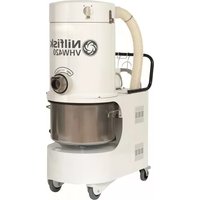
| Brand | Nilfisk |
| Model | IVT1000CR |
| Category | Industrial vacuum cleaner |
| Dimensions (diameter x height) | Ø30 x 62.5 cm (standard version) |
| Weight | 7.75 kg (standard version) / 9.2 kg (H version) |
| Power supply | 220-240 V ~ 50-60 Hz (EU) / 110-120 V ~ 50-60 Hz (US) |
| Nominal power consumption | 1200 W (EU) / 1100 W (US) |
| Dust class | M (standard version) or H (H version) |
| Main filtration | Goretex PTFE (class M) / HEPA H13 (class H) |
| Exhaust filtration | ULPA U15 |
| Container capacity | 12.5 L |
| Dust bag capacity | 6.5 L (class M) / 8 L (class H) |
| Sound level at 1.5 m | 61 dB(A) |
| Protection rating | IP40 |
| Material | Stainless steel AISI 316 |
| Usage | Dry, non-flammable, non-toxic dusts (class M); hazardous dusts (class H); clean rooms ISO 5/6 |
| Features | Pressure gauge (class H), safety valve, Safe Pack option, safety bag (class H) |
| Maintenance | Cleaning of the main filter by shaking; replacement of main filter and ULPA; emptying of container and bag change |
| Spare parts | Use only genuine Nilfisk parts |
| Repairability | Entrust electrical repairs to a qualified technician; do not modify the equipment |
Frequently Asked Questions - IVT1000CR NILFISK
User questions about IVT1000CR NILFISK
0 question about this device. Answer the ones you know or ask your own.
Ask a new question about this device
Download the instructions for your Industrial vacuum cleaner in PDF format for free! Find your manual IVT1000CR - NILFISK and take your electronic device back in hand. On this page are published all the documents necessary for the use of your device. IVT1000CR by NILFISK.
USER MANUAL IVT1000CR NILFISK
Operating Instructions
Bedienungsanleitung
Gebruiksaaanwijzing
Mode d'emploi
Istruzioni per uso
Hasznalati utas it as
Navodila za uporabo
Návod k obsluhe
Kasutusjuhend
Fig 2 standardmaskin
- Motordeksen, inkl. händtak
- Av/pa-knapp
- Deksel over utblåsingsfilter
- ULPA U 15-utblåsingsfilter
- Toppbeholder
- Hovedfilter klasse "M" Goretex® PTFE-filter
- Stovbeholder
- Klemmer av rustfritt stål
- Vogn
Fig. 3 Maskin i "H"-klassen
- Motordeksen, inkl. händtak
- Av/pa- knapp
- Deksel over utblåsingsfilter
- ULPA U 15-utblåsingsfilter
- Toppbeholder
- Vakuummäler / manometer
- "H"-klasse HEPA H 13-filter
- Stovbeholder
- Blinddeksel for inntak
- Klemmer av rustfritt stål
- Vogn
Fig. 4 "Safe Pack"-maskin
- Motordeksen, inkl. handtak
- Av/på-knapp
- Deksel over utbläsingsfilter
- ULPA U 15-utblösingsfilter
- Toppbeholder
- "Safe pack"-enhet
- HEPA H 13-filter festet på innsiden av "Safe Pack"-enheten
- Klemmer av rustfritt stål
- Vogn
4 - Sikkerhet
Merk!!
Fest stovposen pa fologende mate:
Bryt igennom stovposens perforering, og plasser den i den nedre beholderen.
Trekk den blå plastplaten på støvposen over inntaket med begge hender.
Sette inn "Safe Bag"
The operational safety of the machine in your possession is Entrusted to those who work with it every day.
Caution: Read instruction manual before operating and maintaining the appliance.
"IMPORTANT NOTE!"
This manual has been compiled in order to inform machine users about the precautions and regulations to ensure their safety and allow the vacuum to remain in good working condition.
Personnel authorised to work with the machine must understand the manual before the machine is started. Keep the manual near the machine, in a protected and dry place away from direct sunlight and ready to hand for future reference when required.
This manual reflects the state-of-the-art technology at the time of sale and cannot be considered adequate if modifications are subsequently made except in cases where a Nilfisk-Advance kit for the machine has been installed.
The manufacturer reserves the right to update the production range and relevant manuals without being obliged to update previous machines and manuals. Consult your nearest After-Sales Service Centre or Nilfisk-Advance in case of doubt.
Description:
This machine has been designed to collect shavings, scraps, dust and various waste materials.
The vacuum has been designed and built to operate in industrial environment such as clean room areas where it can work for normal cleaning purposes.
The air passes through a filtering surface where solids in suspension are retained.
The machine is as standard equipped with ULPA U 15 exhaust filters, which makes the machine suitable for use in clean room areas ISO 5 and ISO 6 (under normal circumstances even ISO class 4).
An "H" class version equipped with upstream HEPA H 13 filter and downstream ULPA U 15 filter is also available. This machine is suitable for dust hazardous to health in class "H".
The IVT 1000 CR / IVT 1000 CR “H” can be equipped with standard dust bag’s (non hazardous dust) or a “safe bag” suitable for hazardous dust class “H”
A "Safe Pack" version of the machine is also available - this machine features a dust collection bin with built in HEPA filter - to be used for hazardous dust. The whole bin is replaced after use.
The pressure gauge installed on the machine (class "H" only) warns the operator of the filter conditions: an increase in pressure corresponds to a reduction in the suction power of the machine.
The high quality of the vacuum cleaner is guaranteed by the strictest tests.
The machine is manufactured in stainless steel AISI 316. All materials and components are subjected to a series of strict inspections during the various production phases in order to ascertain compliance with the established high quality standards.
2 - Safety precautions
2.1 - General precautions
Become thoroughly familiar with the content of this manual before starting, using, servicing or operating the vacuum in any way.
Never allow unauthorised personnel to work on the vacuum.
Never wear unbuttoned or loose clothing, which could be caught by the vacuum. Wear appropriate clothing.
Consult your employer about the current safety provisions and specific accident-preventing devices to use in order to ensure personal safety.
The area where maintenance operations are carried out (ordinary or extraordinary) must always be clean and dry.
Suitable tools must always be available.
Repairs must only be carried out when the machine is at a standstill and disconnected from the electricity supply. Never carry out repairs without having first received the necessary authorisation.
2.2 Important warnings
To reduce the risk of fire, electric shock, or injury: Do not leave the appliance unattended when plugged in. Unplug from outlet when not in use and for servicing.
Do not allow to be used as a toy. Close attention is necessary when used by or near children.
Use only as described in this manual. Use only Manufacture's recommended accessories and spare parts.
Do not use with damaged cord or plug. If the appliance is not working as it should, has been dropped, damaged, left outdoors, or dropped into water, return it to a service center.
Do not pull or carry by cord, use cord as handle, close a door on cord, or pull cord around sharp edges or corners. Do not run appliance over cord. Keep cord away from heated surfaces.
Do not unplug by pulling on cord. To unplug, grasp the plug, not the cord.
Do not handle plug or appliance with wet hands.
Do not put any objects into openings. Do not use with any opening blocked; keep free of dust, lint, hair, and anything that may reduce airflow.
Keep hair, loose clothing, fingers, and all parts of the body away from openings and moving parts.
Under no circumstances should the machine be used for picking up hot material. In particular the machine must not be used for cleaning open and closed fireplaces, ovens or similar that contain warm or gloving ashes.
Do not use without dust bag and/or filters in place.
Turn off all controls before unplugging.
Use extra care when cleaning on stairs.
The machine must not be used for picking up combustible or explosive materials, nor should it be used in an explosive atmosphere.
2.3 Grounding instructions
This appliance must be grounded. If it should malfunction or break down, grounding provides a path of least resistance for electric current to reduce the risk of electric shock. The plug must be inserted into an appropriate socket that is properly installed and grounded in accordance with all local codes and ordinances.
WARNING - improper connection of the equipment grounding conductor can result in a risk of electrical shock.
Check with a qualified electrician or service person if you are in doubt as to whether the outlet is properly grounded. Do not modify the plug supplied with the appliance – if it will not fit the socket, have a proper one installed by a qualified electrician.
Attention!!
Under no circumstances must the user tamper with the equipment.
All attempts by the user or by unauthorised personnel to dismantle, modify or, more generally, tamper with any part of the vacuum shall void the guarantee.
Contact your nearest
After-Sales Service Centre in the event of faults.
3 - Machine data
3.1 Identification data.
Always state all the identification data on the machine when ever you contact Nilfisk-Advance after sales service.
Exact identification of the machine model and serial number will help prevent incorrect information from being given.
The identification plate with the machine data is shown in fig. 1
A Type
B Electrical Power
C Serial number - yywwXXXX
yy=year ww = week XXXX = number
D Operating Frequency
E Dust class Category
F Ref. number
G Voltage
H Max. Current
3.2 - Main parts (fig. 2 / 3 / 4)
The following list of main parts will help users to understand the terms used in this manual.
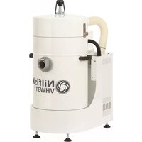
Fig 2 standard machine
- Motor head incl. handle
- On / Off button
- Exhaust filter cover
4.ULPA U 15 exhaust filter - Top container
- Main filter "M" class Goretex® PTFE filter
- Dust container
- Stainless steel clamps
- Trolley
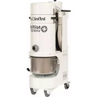
Fig. 3 "H" class machine
- Motor head incl. handle
- On / Off button
- Exhaust filter cover
4.ULPA U 15 exhaust filter - Top container
- Vacuum Gauge / Manometer
- "H" class HEPA H 13 filter
- Dust container
- Blind cover for inlet
- Stainless steel clamps
- Stainless steel clamps
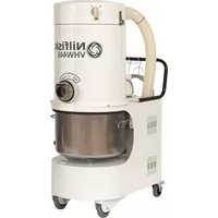
Fig. 4 "Safe Pack" machine
- Motor head incl. handle
- On / Off button
- Exhaust filter cover
4.ULPA U 15 exhaust filter - Top container
- "Safe pack" unit
- HEPA H 13 filter fixed inside safe pack unit
- Stainless steel clamps
- Trolley
4 - Safety
Attention!!
Check that all clamps are correctly positioned and working correctly before starting and using the machine.
Never tamper with the safety devices.
Always check that the protection and safety devices are mounted and working at the beginning of each work shift or before using the machine. If this is not the case, switch off the vacuum and report fault.
The vacuum has been manufactured with particular attention to the operator's safety.
Comply with the maintenance and technical assistance procedures and information given in this manual.
Never use compressed air to clean the machine or its components.
Never open the waste container whilst the vacuum is operating.
Before beginning electrical connection, check that the voltage
and frequency values are those indicated on the data plate of the machine.
Connect the machine to the electricity main with an efficient ground circuit.
Only authorized personnel must be allowed to work on the electrical part of the machine and this must always be disconnected from the electricity main.
Never move the vacuum by pulling the power cable. This may damage the vacuum itself and the operator may be exposed to electric shocks
5 - Testing, delivery, installation
5.1 - Testing
The machine has been tested in our plant in order to ensure that it operates correctly. Tests on the suction values are carried out during this phase.
This ensures that the vacuum has been optimised according to the job for which it was designed.
5.2 - Delivery and handling
The machine is delivered, in a cardboard box. When receiving the machine check for concealed damage. If damage is discovered, immediately fil complaint with the carrier.
The machine can be stored at temperatures between 0 and 50^ , and 65% relative humidity.
Before storage the machine must always be cleaned in accordance with the instructions.
The machine can be operated in the temperature range -5 to +50^ and 65% relative humidity.
The delivery packaging should be disposed of in accordance with the relevant statutory regulations.
Dispose of a machine, which is no longer usable, in accordance with the relevant statutory regulations.
Only use approved commercially available, noncombustible and non-toxic solvents for the purpose of cleaning the machine Stainless steel body parts and accessories can be cleaned in an autoclave at 121^
5.3 - Certificate of guarantee
The certificate of guarantee is packed with the vacuum.
5.4 - Installing the vacuum
Attention!!
The user shall be responsible for ensuring that installation
complies with the local statutory regulations.
A qualified technician, who has read and understood the instructions herein, must install the equipment.
The floor on which the vacuum must operate should be level, flat and smooth.
If the vacuum is to work in a fixed position, allow ample space all round in order to ensure freedom of movement and make sure that the maintenance staff to operate with ease.
5.5 - Connecting to the electricity main Attention!!
Check that the voltage and frequency values of the electricity main correspond to the values indicated on the data plate described in paragraph 3.1 (data plate) Specialised personnel must carry out all installation and maintenance work on electrical parts.
Connect the equipment to an efficient earth.
Ensure that the electrical supply matches the machine rating plate.
6 - Controls (Fig. 5)
- On / Off button
- Vacuum Gauge / Manometer ("H" class machine only)
7 — Starting and stopping
7.1 - Caution
Attention!!
Unauthorized personnel are forbidden to use the vacuum.
7.2 - Starting / Stopping
Check that the machine has been effectively connected to the electricity main. In particular, check that the main voltage and frequency values correspond to those indicated on the data plate. (see fig. 1)
Fit the accessories to the suction inlet. Use the stainless steel clamp to fix the hose to the inlet.
Place the vacuum near the place of use, then lock the wheels by pressing levers downwards.
The machine is switched ON or OFF by pressing the grey button on the upper part of the motor.
8 - Using the vacuum (fig. 7)
8.1 — Correct use of the vacuum
Before using the machine, connect the suction pipe to the inlet as indicated in paragraph 7.2.
Keep long suction pipes as straight as possible.
Do not allow them to bend or twist as this will cause excessive wear and clogging.
When the vacuum is powered, suction is created at the pipe inlet and this sucks in the waste material.
This waste material passes through the pipe and accessories through the inlet "4" until it reaches container "6".
A Org. Nilfisk dustbag can be used in the standard machine.
To release the container, unfasten the stainless steel clamp and lift off the upper part with the motor/filter section.
Fix the dust bag as follows:
Pierce the dust bag's perforation and place it in the lower container.
Pull the blue dust bag plastic plate over the suction inlet with both hands.
Unfold the dust bag carefully. Replace the top container and lock the stainless steel clamp.
Note
The suction efficiency depends on the size and quality of the dust bag. Use original Nilfisk bags only. If non-Nilfisk dust bags are used, and airflow restricted, overheating of the motor and subsequent damage may occur.
"H" class only:
A "Safe Bag" system is used for the "H" class machine. The Safe Bag system consists of a dust bag approved by BIA for class "M". The dust bag is reinforced with a mesh and encapsulated in a plastic bag.
Insert the dust bag into the container. Its flange must point at the inlet.
Now push the flange onto the inlet until it fits tight.
The plastic bag has to fit the bottom and walls of the container. Tear the edge of the bag above the edge of the container and smooth it down.
"Safe Pack" only:
Ensure that the motor and top container fits correctly on top of the safe pack unit before starting the machine.
The safe pack unit is a "throw away" unit, which is manufactured to hold dust hazardous to health.
8.2 — Cleaning the main filter (standard Machine)
To keep suction power at a constant level the filter must be kept as clean as possible by shaking it at regular intervals.
Dismount the motor unit by opening the stainless steel clamp.
Take the bottom plate of the filter and pull it upwards and shake slightly. Don't remove the hose while shaking. The filter must not be washed or brushed!
"H" class only
The system is fitted with a vacuum gauge / manometer that allows you to monitor the minimal airflow in order to guarantee an optimal air speed within the suction hose. When you lift the floor nozzle off the surface that is being cleaned and the manometer's needle moves from the green zone into the red one, the dust bag is full and needs to be replaced.
Attention:
The level of material inside the dust bag has to be checked at regular intervals. Monitoring the level strictly by means of the manometer is not a 100 per cent guarantee that the bag is not full.
Attention:
There is no device for cleaning the main filter.
When the dust bag has been replaced and the manometer's needle does not return to the green zone, the main filter needs to be replaced as well.
8.3 — Emptying the container / changing the bag (fig. 9)
First of all, switch the motor off and wait a moment until the dust inside the machine has settled down. Then you can separate the dust collecting container from the upper part of the machine:
Switch the motor on in order to prevent dust falling down from the filter.
Open the stainless steel clamp, now lift off the upper part and let it rest on the support frame. Replace the disposal system, the bag.
Lift the upper part above the machine.
Switch the motor off.
Put the upper part on the machine and secure by locking the clamp.
"H" class only: (fig. 10)
Using a Dust Safe Bag system, Dust class H
Once the dust bag is full
Disconnect the vacuum compensation line from the system.
Open the clamps and lift the upper part.
Switch the motor on in order to prevent dust falling down from the filter.
Leave the hose connected or close by shutter cap! Now lift off the upper part and replace the safe bag disposal system.
After opening the appliance detach the plastic bag lying across the bin rim carefully, press the opening together and seal it.
Detach the back of the connecting flange by briefly and firmly pressing downwards at an angle, holding the front firmly on the connection piece as you do so.
The flexible plastic-pipe joint is now visible and can be tied off securely with the plastic cable tie simply by pulling it together.
Having ensured that no dust can escape, now also detach the front part of the flange from the connection piece.
Fitting the Dust safe Bag
Place the special dust bag flat in the bin with its opening pointing towards the bin inlet.
Now slide the opening in the special dust bag on to the bin inlet as far as it will go - without any turning.
Then fold the plastic bag down over the bin rim.
Now pull the part of the plastic bag overlapping the bin rim tight against the flange (before reattaching the top and bottom sections of the vacuum cleaner).
Lift the upper part above the machine.
Switch the motor off.
Put the upper part on the machine and secure with locking clamp.
Connect the vacuum compensation line to the system.
9 — Dustclasses
Use in compliance with the standards.
Check which dustclass your machine is suited for (see identification plate).
The machine must not be used for several categories at the same time, unless suitable accessories are used.
Dust Class "L"
(Light hazard - defined by EN 60335-2-69).
This industrial vacuum is approved according to EN 60335-2-69 for category of use "L" and is fit to suck dry, non flammable and non-toxic dust with MAK > 1mg / m? values; the clean air is conveyed back into the place of work.
Dust class "M"
(Medium hazard - defined by EN 60335-2-69).
This industrial vacuum is approved according to EN
60335- 2- 69 for category of use “M” and is fit to
suck dry, non flammable and non-toxic dust with
MAK>0.1mg/m? values; the clean air is conveyed back into the place of work.
Dust class "H"
(High hazard - defined by EN 60335-2-69).
This industrial vacuum is approved according to EN
60335-2-69 for category of use "H" and is fit to suck dry, non flammable and non-toxic dust with all MAK
limiting values as well as dry, non flammable dusts of carcinogenic substances. The cleaned air is fed back to the workplace atmosphere
10 — Maintenance
10.1 - Foreword
Attention!!
All maintenance and cleaning operations must be carried out when the vacuum is off and disconnected from the electricity main.
The suction unit needs no particular maintenance or lubrication.
Remember, however, that correct use and servicing are essential if the safety and efficiency of the vacuum are to be guaranteed.
To ensure regular and constant operation and to prevent the warranty from becoming void, only ever use genuine Nilfisk-Advance A/S spare parts when repairs are needed.
10.2 - Checks and inspections on start-up
The customer should proceed with the following inspections to ensure that the vacuum has not been damaged during transportation.
10.2.1 - Before starting:
Check that the mains voltage value corresponds to that for which the machine is preset (see data plate in paragraph 3.1 fig. 1);
10.2.2 - With the vacuum operating
check that all the air seals are perfectly tight; check that all fixed protections are efficient; proceed with suction tests using the same materials as those used during work. This will ascertain whether all parts of the vacuum operate correctly.
10.3 - Routine maintenance
Strictly comply with the following operations to ensure that the vacuum remains in a constantly reliable condition.
10.3.1 — Before each work shift:
Check that all warning and danger plates are fixed and legible.
Replace them if they are damaged or incomplete.
Check that the waste container is empty.
Empty it if this is not the case. See paragraph 8.3.
10.3.2 - Cleaning the vacuum unit:
The Stainless steel parts can be cleaned by normal cleaning methods using standard sanitizers, and they can also be cleaned in a standard Autoclave unit at 121^ .
All other components can be cleaned using standard cleaning methods.
11 - Changing the filter
11.1 - Changing the main filter (fig. 11)
Attention!!
When the vacuum has been used on materials that are hazardous to the operator's health, maintenance staff must wear suitable personal protection equipment.
When replacing the primary filter. Work outdoors if possible. The old filter must be disposed of in a special plastic bag.
Loosen the clamp fixing the filter assembly on the machine.
Remove the motorhead from the machine.
Detach the gasket securing the filter ring at the bottom of the top container.
Unclip the filter in the top of the container and place the filter in a plastic bag.
Close the plastic bag containing the filter.
If this is soiled with toxic or dangerous dust, do not throw it away. Hand it over to the authorities that are authorized to dispose of such waste.
Change the main filter and the "H" class filter with particular care, above all use mask type P3.
Attention!!
Filter replacement is an important operation.
The filter must be replaced with one of identical characteristics, exposed filtering area and category.
Failure to comply with these regulations could jeopardize the correct operation of the vacuum.
Obtain a filter with a identical characteristics to the previous one.
Fit the filter in the container as described above in opposite order.
11.2 — Changing the exhaust filter (fig. 12)
Disconnect the vacuum cleaner from the power supply before starting the work!
attention: Observe correct operator protection in accordance to regulations against material kept in the ULPA filter.
Removing the handle
Detach the handle by unscrewing the two screws.
Release the handle by a gentle downward pressure at its centre.
Press and release the handle from the recesses.
Removing and replacing the filter cartridge and gaskets
Unscrew the four screws.
Lift-away the stainless steel housing with filter cartridge.
Replace the filter cartridge and gaskets.
Refit the filter housing by pressing on the top, to mount the four screws.
Remount the handle and fix in position with the 2 screws.
The dismounted and replaced exhaust filter must be covered with a plastic bag and disposed of in the appropriate way.
Execute the change of the primary filter and of the exhaust filter with particular care above all use the mask type P3.
Note
The exhaust filter is toxic waste and must be treated as such.
Hand it over to one of the authorities authorized to dispose of such materials.
12. — Recommended spares
The following is a list of spare parts that should be kept ready at hand in order to speed up maintenance work.
Part no.:
Description:
02171000
DUST SAFE
81620000
DUST BAG 6.5 L, 5 PCS
80556600
ULPA FILTER KIT
80353000
SEALING FOR INLET
61909800
GORE-TEX FILTER
80386700
SEALING FOR CONTAINER
13. — Trouble-shooting
- the motor will not start
- a fuse may have blown and needs replacing.
- the cable or the wall socket may be defective and needs checking.
the suction power is reduced
- the dust bag may be full and needs replacing,
- the filter may be clogged and needs shaking,
- The by pass valve is open
The by pass valve protects the motors against an overheating that may occur when there is not enough cooling air.
You should not release this mechanism unnecessarily by closing the suction inlet with your hand while the machine is working.
When the hose or the tube is blocked or the filter needs to be cleaned, the airflow is interrupted or not longer sufficient and the by pass valve opens. It is not necessary to shut down the system while removing the blockage.
Having done that, you may continue with your work.
- the vacuum cleaner stops
- the thermal cut-out has switched off the motor as a result of an obstruction of the hose, wand or nozzle. Remove the cause of the obstruction.
- when the motor is cool, it will automatically start again.
| Specifications | IVT1000 CR EU - UK 220-240V | IVT1000CRH EU - UK 220-240V | IVT1000 CR Safe Pack EU - UK 220-240V | IVT1000 CR US 110-120V | IVT1000CRH US 110-120V | IVT1000 CR Safe Pack US 110-120V |
| Rated power W | 1200 | 1200 | 1200 | 1100 | 1100 | 1100 |
| DUST CLASS | M | H | H | M | H | H |
| FREQUENCY (Hz) | 50-60 | 50-60 | 50-60 | 50-60 | 50-60 | 50-60 |
| GROUNDED | JA | JA | JA | JA | JA | JA |
| Protection grade (moist., dust) - | IP40 | IP40 | IP40 | IP40 | IP40 | IP40 |
| Airflow without hose l/sec | 38 | 35 | 35 | 36 | 34 | 34 |
| Vacuum kPa | 19,8 | 20 | 20 | 19,6 | 19,8 | 19,8 |
| VACUUM MAX (KPA) | 19,8 | 20 | 20 | 19,6 | 19,8 | 19,8 |
| Suction power with hose W | 250 | 236 | 236 | 240 | 232 | 232 |
| Sound pressure level at 1.5 m (ISO 3744) | 61 | 61 | 61 | 61 | 61 | 61 |
| MAIN FILTER TYPE | GORETEX PTFE | HEPA H13 | HEPA H13 | GORETEX PTFE | HEPA H13 | HEPA H13 |
| Main filter area cm2 | 2100 | 2573 | 2573 | 2100 | 2573 | 2573 |
| Exhaust filter, ULPA, surface area U15 cm2 | 2573 | 2573 | 2573 | 2573 | 2573 | 2573 |
| Container capacity I | 12,5 | 12,5 | - | 12,5 | 12,5 | - |
| Dust bag capacity I | 6,5 | 8 | 6,5 | 6,5 | 8 | 6,5 |
| INLET (MM) | 32 | 32 | 32 | 32 | 32 | 32 |
| LENGTH X WIDTH X HEIGHT (CM) | Ø30 x 62,5 | Ø30 x 72,5 | Ø30 x 70 | Ø30 x 62,5 | Ø30 x 72,5 | Ø30 X 70 |
| Weight kg | 7,75 | 9,2 | 8,2 | 7,75 | 9,2 | 8,2 |
DE
1 - Einleitung
Fig. 4 "Safe Pack" machine
- Motorblok incl. handgreep
- Aan / Uit knop
- Kapuitblaasfilter
- ULPA U 15uitblaasfilter
- Bovenste container
- "Safe pack" unit
- HEPA H 13 filter bevestigd in de safe pack unit
- Roestvrij stalen klemmen
- Trolley
4 - Veiligkeit
Opgelet!!
Fig 2 Machine standard
The cleaned air is fed back to the workplace atmosphere
10 - Manutenção
10.1 - Preambulo
Atenção!!
HnkOrda He donyckaTte Iu, He nmeiox pa3peweHne, K 3Kcnpyaataun nbilecoca.
HnKoIa He Hocnte paccterHyTuIO nIIc Cbo6OHyOdExy, KOTopra MoKeT nonactb By3JIb Iblncoca. Hocnte NOxOJMyU OdeXy.
06paTntecb K CBOemy pa6oToaTeJIIO 3a INHΦOpMaunnei O MEPax 6e3ONaChOCTN I O CnEuaJIbHbIX CpeIcTBax IpeODTbPaUeHnI HeCuaCTbIX ClyuYaeB, KOtOpIe MOryt NCNoJIb3OBaTbcra IJr IInuHoi 6e3ONaChOCTN.
PomeeHn, B KOTOpbIX IPOUN3BOOHTc TExHNueckoe 06CnyxuBaHne n peMOHT (TeKyuIIN nn BHeOuepeDHOJ), DOJIHKbI 6bITb YNCTbIMN u CyXUMN.
Bcerda doJIxHbI 6bITb B HaJIuHn COOTBeTCTByUOuNe HNCTpyMeHTbl.
Bo BpempeMOHTbIX pa6Ot, nbIeocOdoJXeH haoiNTbcB HeNoDBuXHOM COCToHnN, CJIeDyET OTCoeHNHTb erO OT 3JeKTPoCHa6xHeH.N. HeIb3a BblOnHrTa peMOHTbIe pa6Otbl, He NOLyUHb Ha 3TO cneuaJIbHOe pa3peWeHne.
2.2 Baxhble npedynpexdeHna
ДяТОТO,чTO6bl CHN3NTb pNUCK BO3HKNKHOBEHnI NOXapa, nopaxKeHnI 3JIeKTPnueCkM TOKOM IINI NOnyUeHnI TpaBMbl: He octaBIAIte BkLIOUeHHbI nbIeCoc 6e3 npucMOtpa.
OTKJIIOUaIte NbIeCOC OT CeTn NITAHNIA,ecIN Bbl IM He NOLb3yeTeCb,NII NO BVpeMЯ pOBoEeHNApa6OT nToTexHnueCKOMy 06cIyJXnBaHnIO.
He donyckaIte nCnoJIb3OBAHnI nbIeLcOca B kaueCTBe IrgpuKn. Ppi 3KcIIpyatauIIN nbIeLcOca B6In3n Deten, Tpe6yeTc oO6oe BHMaHne.
NcnoIb3yIte nbIeoc TOIbKO cOrIaCHO IHCTpyKUIMdAnHOrO pykoBDCTBa. NcnoIb3yIte ToIbKO peKOMeHNdyEmble npOn3BODnTeJem akCECCyapbl 3aNaChblde TaII.
He nCpOJIb3yIte nbIeoc, ecnIOBpeJdeHb IHyp nI IN BnIka. EcIn nbIeoc He pa6OtaET TaK, KaK HxKHO, ecIn Bb erO ypoHnIn, ecn OH NOBpeJdeH, 6bl OcTaBLeH BHe NOMEeHn IN eCIn bbl erO ypoHnIn B BodY, CneJeYET OTnpaBtB erO B cepBncbl ueHTp.
He TAHnTe PbIeCoc 3a Whyp, He NcNoJIb3yIte Whhyp B KaueCTBe pyKoTKn, He 3aKpbIbAitE DBePb, ecIn NO dBepbH haxOuITcra Hhyp, I He TAHnTe Whyp nO OCTpbIM yrIam INI KpaAM. He nepee3kaIte Whyp PbIeNcoCOM. DepeXnTe Whyp PoJaIbWe ot IIO6blx HarPeTbIX NOBepXHOcTei.
He OTKlnouaTe PbIeCoc OT cETn PtHaHn, NotaHyB 3a WHyp. IaTOrO, yTo6bI OTKlnouHTb PbIeCoc, OT cETn PtTaHn, BO3bmITecb 3a BnIKy, a He 3a WHyp.
He npkacaTecb K BnIke nIIN nbIeCocy MokpbIM pyKaAMn. He NomeuAaTe KaKne-JIn6o PnpEdMeTb B OTBepCTn. He Nol3yntecb PbIEcOCOM pNp 3a6NoKOpOBaHOM OTBepCTn, OOnuAaTe OTBepCTnO T rpa3N, Nyxa, BOJoc nIIN IIO6bIX npEMeTOB, KOTOpBE MOrYT CNH3NTb NOTOK BO3dyxa.
He donyckaIte nonaDaHnB OJoc, DeTaeN OeJxbl, naIbceB n dpyrnx yactey TeLa B OTBepCTn IIN BpaauoUneCe y3JIbI nbIneCoca.
Hn npKaknx 06cTOnTeBcTBax nbIneCoc He dONJKeH nCNoJIb3OBaTbcraIc6opapackaJIeHHbIX MaTePnaNoB.
B YaCTHOCTN, NblIEcOC HeJIb3I NCNoIb3ObaT bIa YIcNTK OTKpbITbIX I 3aKpbITbIX KaMHOB, Neey IIN aHaIOnrUHbIX O6bEkoT B KOTOpbIX MOrYt CoDePkaTbC TeIIa IIN TNeIOJua 30Ja.
He 3Kcnpnyatnpyute nbIecoc, ecn He yctaHOBneHb nbIeBOmewok n/nnn fNbTpbl.
IpeD OTKJIoueHnEM NblncOca OT CeTn NITaHn, BbIKJIOUHTe
BCE KHONKUynpaBHeHn.
Ppiy6opke lecTHnC cneJyET 6bIb oco6eHHO octopoKhbIM. HeIb3a IcNoJIb3OBaTb IIIeCoc dIra C6opa IerKO BOCIIaMeHHeIOUxNCr NIN B3pbIBOONaCHbIX MaTePnaJIOB, a TAKKe HeJIb3a IcNoJIb3OBaTb IIIeCoc BO B3pbIBOONaCHO atmocfope.
2.3 INCHCTpykCnI NO 3a3eMJIeHnIO
Даннь пьлесoc дожен 6ыт bзам leн.Еп npоизовдсбои лжелрчecтba ИИnpьлесoc bblidet n3 STPО,Замлелпобе obecneунBaetpyb haIMeHbIero COnpoTINBJIeHЯ Ддл ЗлжелрчecKOrO ToKa C ZeIbIO ChInxeHЯ рСКА ПОражehЯллжелрчecKMToKOM.ВИнka DoLЖHa BCTaJЯТСВСВ COOTBETCTBYUQYU PO3ETKY,празИьН OYCTAHOBЛeHHyU 3aZeMЛeHHyU BCOOTBETCTBmN CO BCEMМecTHbIMN HopMaTINBbIMN aKTAMn paCnOpЯжehЯMn.
BHIMAHNE - He npabnIbHoe coeINHeHne 3a3emIooIeTo npoBoda MoKeT npuBeCTN K nopaxeHIO 3JIeKtpueckm TOKOM.
ПрOKOHcUbIbTnpyIeTcB c KBaJIINФицИpoBaHbIM 3JeKTpNKOM Илс cIeциаIInCTOM NO TexHnueCKOMy O6ClyuXnbAHIO, ecII СOMHeBaTeCtB TOM, IpraBulNBO JIN 3a3eMJIeHa pO3eTKa. He ВИДОИЗМЕнЯТе BUNKy UHypa NITaHЯ, KOTOpbIM ChA6Jxeh пьЛeOC-ecII INBILKa He NOДхОДNT ДЯ рO3eTKN, ДЯ УCTaHOBNK COOTBeTCTBHyOseI pO3eTKN, HeO6XoDmO BOcONOLb3OBaTbCS I NOMOsbIb KBaJIINФицИpoBaHnHO 3JeKTpNKa.
BHHMaHHe!!
Hn np KaKnx ycIOBnX, NOJIb3OBaTeJb He DoJIkeH CaM nbITaTbCpaMOHTnpOBAtB nbIeoc.
Bce nONbTKn NOnb3OBaTeJn nn HeabTOpN3uPObaHHOro nepcoHaJa pa3O6paTb, MoINΦnUcnpOBAtB nn OTpeMOHTnpOBA TbIO6yO DeTaJb nbIeocca npNBeDyt K aHHynIpOBaHnIO rapaANTn. B clyueae HencnpaBHOCTn nbIeococa, 6bpaauTeCb B 6NIkawn ceHTp nocJeepndaKHOro 06cnyKuBaHna.
3 -Данны O nbilecoce
3.1. NdeHTnФикauNoHHbIe daHHbIe.
Pn o6paueHn B ceHtp nocIe npdoaJxHO 06cIyXuBaHn
KoMpaHn Nilfisk-Advance, Bcerda yka3bIbAte BCE
UeHTnФHKaUHbIe DaHHbIe PblncOca.
ToHna IeHTnФHKaUHm MOeHN PbIeOCa N cepNHyB
Homep No3BOJAT N36EkaTb PpeDcTaBLeHn HeppaBnBHO
NHΦOpMaun.
Ta6JIuKa c TexHnueckmM daHHbIMn PbIeOCa N3o6paXeHa
Ha Pnc.1
Φ Tn
B ΘeKtpnueckaM OuHocTb
C CepiHbI Homep - yywwXXXX
(yy = rOД, WW = HeДeЯ XXXX = HoMeP
D Pa6o7a yactota
E Kateropn no c6opy nbln
FHomepJJIaCCblkN
HnKOrda He OTKpbBaIte KOHTeHep Ira c6opa Mycopa npa6oTaHOUeM PbIeCoCe.
Ipeed Tem, kak NODKIIOuHTb nbilecoc K cetn 3neKtpueeCKOro nItaHn, npOBepbTe, COOTBeTCTByIOT JIn 3NaYeHn HaipJxEHHn U qactotb 3NaYeHnM, yKa3aHHbIM B nacnOpTHoT Ta6JIuYke nbilecoca.
IopKJIIOUaJIte nbIeNcOc K cETn 3JIeKTPuYeCKoR O nITAHn, ImeUeJ pa6OtaHouyU cenb 3a3EmJeHN.
Tolbko aTbOp3nOBaHHb nepcoHaJ moKet 6bItb DOnyuIeH K pa6Ote C 3JIeKtpnueckmN y3JaMn PbJIeCoca, PbJIeCoc DOLJIeH 6bItb
OTKlnHoueH OT CETn NHTaHna.
HeIb3a nepeDnRaTb nbIeCoc,NOTaHyB 3a WHyp nITaHna.
TakIM o6pa3OM, MoKet 6bItb NOBpeKdEh cAm PbJIeCOC, a onepaTop MoKet 6bItb NopaxeH 3NeKtpnueCKM TOKOM.
5 - TectnipoBaanHe, IOCTaBka, yCTaHOBka
5.1 - TectnopoBaHne
TapaHTnHoe CBnIeTeJIbCTBO yNaKOBbIbAetCra BMeCTe C nbJIneCOCOM.
5.4 - yctaHOBka nbInecoCa
Bhumahne!!
Пользова teль OTbeуат 3a yctaHOBky nbIeCOca
B COOTBETCTBUN C MeCTHBIMN HOPMaTINBBHIMn aKTAMN.
O6opydoBaHne dOnJxeh yCTaHaBnBaTb KBaIINΦuNpObaHHbI cpeuaJIncT, KOtOpbI O3HaKOMnCc HcTpkyUmaMn, npEiCTaBLeHHbIMn B DaHHOM pyKOBOdCTBe, I NOHJI INX coepjkaHne.
Iobepxhoctb nola,Ha KOTOPOM 3KcnpyaTupyetc npIneoc, doJIkha 6bIbpoBHOi, IIOCKoN rIaNKOi.
Ecnn nbilecoCdoJxeh 3KcnpnyatnpoBaTb8B
3aΦnKcnpoBaHHOM NOLOXeHnn, BOKpyr DOLJxHO 6bITb
dOCTaTOUHO CBO6oHOrO npocTpaHCTBa dIy o6ecneueHH
cbo6oDbI nepeBnHexHn. CneDyET TaKxye 6ntcB TOM,
TOO6CnyKbAIOUnn nepcoHaI pa6oTaET 6e3 3aTpudHeHn.
Ctporo BbIOpHnIe TnpBVeDHeHbIe HNKe Opeaun IJnIpoIepKaHnI PbIeCoCA BHaJeXHom pa6Oyem COCToHnIBTeueHne BCero Cpoka CnyK6bl.
YcTaHOBnTe KOpnyc Ha MeCTo, 3aKpyTnTe YeTBpe Wypyna. YcTaHOBnTe Ha MeCTo pyKoRrKy N 3aKpeNITe C NOMOu2 WypynOB.
ChaTbI BbIXLOHNoH ΦnIbTp DoJXeH 6bIb NOMeUeH B nlaCTNKOBbl NaKET uYTuIN3OBAH COOTBeTCTByIOUcM cnOCo6oM.
3aMeHy nepBnHOro fIbTpra n BbIXonHoro fIbTpap npOn3BOdnte C 60JbWoi OCTOpOxHOcTbU N cNpONb3yInTe 3aunTHyIO Macky dJa Iuca Tuna P3.
Приимechаиме
BbIXNoHnO ΦnIbTp RaJIaTcT OTKCuHbIM OTXoDOM, I C Hm HnyKHO oBaPauTaTcCoOTBETCTBeHNO.
CneIyET nepeTaB erO B yupeKdEHe, KOTOpoe 3aHMaetcYtIN3aUneTaknX MaTePnaJIOB.
13. - YcTpaHHeHne HEnCnpaBHOCTeI
CHIXEHa MOUHOCTb BCaCbIBaHn
MOXET 6bITb 3aONHeH MeWOK dJIa Nbln, CJeDyET 3aMeHHTb eRO,
MOKet 6bITb 3acopeH ΦnIbTp, CJIeIyET BCTpXHyTb erO, OTKpbIT npOnyckHOJ KlaNaH.
PpOynckHoi Klaanan PpeOxpaHReT DBrTaTeIb OT nepeRpeBa, KOtOpB MOKe T pOn3oITn npN HeOCTaTke OXJaDaUoJero BO3Dyxa.
BbI He OJXHbI BcB6O6JaTb DaHHbIMexAHn3M 6e3 HaO6HocTn, 3aKpbBaBcCaBbAIOoee OTBepCTne pykoB npouece pa60tblPiInecoca.
Ecnn shaHn nnn Tpy6a 3a6noKnpoBaHb, nnn 3acopen fnhtp, noDaay B03dyxa nppepbIbaeTcN yBlaeTcN HeOCTaTOOH, B pe3yIbTaTe cero OTKpbIbAEtCn pOnyckHoi Knaan. Het Heo6xOdmoCTN B BbIKNoueHn CnCTembl npu ydaJeHHn pnuynh b6OknDpOKn.
YdaJIb MaTePnA, BbI3BaBwH 6JOKnPOBky, Bbl MoXeTe npOJKNt bpa60ty.
- Пылесoc OCTaHaBnBaETcR
TeNIOBOB BbIKIooaTeJIb BbIKIIOUHIN DBNrTaTeJIb NOp npuHHe BO3HnKHOBeHn Ipo6Kn B WlaHRe, JecTKOM nepexoHNKe nI IN HacAdke. CneJyET ydaJIntb IpeDMeT, o6pa3OBaBwIn npo6Ky.
IOCSJe OXlaJxDeHnI, DBNrTaTeJIb BKJIouHTCra ABTOMATUeCKN.
LV-directivet (Low Voltage)
89/336/E0F
EMC-directivet (Electro Magnetic
Compatibility)
89/392/E0F
EU Declaration of conformity
Manufacturer
NILFISK A/S
Address
Sognevej 25
DK-2605 Brøndby,
Denmark
Telephone
+45 43 23 81 00
Telefax
+45 43 43 77 00
hereby declares that suction cleaners Nilfisk, Type
IVT 1000 CR / IVT 1000 CR »H«
have been manufactured in conformity with the provision in the Council Directives:
73/23/EEC
LV-Directive (Low Voltage Directive)
89/336/EEC
EMC-Directive (Electro Magnetic
89/392/EEC
Compatibility)
M-Directive (Machine)
Jorgen Jensen


setting standards
EMC-directive (compatibiliidae
89/392/EEC
electromagnétique)
M-directive (regulamento
maquinaria)
Nilfisk-Advance A/S
Jorgen Jensen

Nilfisk Advance
setting standards

EMC-Directive (Smernice pro
elettromagnetickou kompatilitu)
89/392/EEC
M-Directive (Smernice pro stroje)
Nilfisk-Advance-A/S
Jorgen Jensen


Nilfisk Advan
setting standards
EMC-Directive (Smernica pre
elektromagneticku kompatilitu)
89/392/EEC
M-Directive (Sernica pre stroje)
Nilfisk-Advance_A/S
Jorgen Jensen


Nilfisk
Advance
setting standards
IpeTeH3n IIO BHeUHemy BNDy N KOMJIeKTHOCTN He IMeHO
Подпсь покураел_
OOO “HnΦnCK-3ДBaHc”, 127015, MockBa, PocCnB, BAtcka yI., 27, CTp 7.
TeI./Фakc(+7095)7839602
e-mail: HYPERLINK "@mailto:consumer@nilfisk-advance.ru" consumer@nilfisk-advance.ru
www.nilfisk-advance.ru
- - Sikkerhet
- Merk!!
- Sette inn "Safe Bag"
- "IMPORTANT NOTE!"
- Description:
- - Safety precautions
- - General precautions
- Important warnings
- Grounding instructions
- Attention!!
- - Machine data
- Identification data.
- - Main parts (fig. 2 / 3 / 4)
- Fig. 3 "H" class machine
- Fig. 4 "Safe Pack" machine
- - Safety
- - Testing, delivery, installation
- - Testing
- - Delivery and handling
- - Certificate of guarantee
- - Installing the vacuum
- - Connecting to the electricity main Attention!!
- - Controls (Fig. 5)
- — Starting and stopping
- - Caution
- - Starting / Stopping
- - Using the vacuum (fig. 7)
- — Correct use of the vacuum
- Note
- "H" class only:
- "Safe Pack" only:
- — Cleaning the main filter (standard Machine)
- "H" class only
- Attention:
- — Emptying the container / changing the bag (fig. 9)
- "H" class only: (fig. 10)
- Fitting the Dust safe Bag
- — Dustclasses
- Dust Class "L"
- Dust class "M"
- Dust class "H"
- — Maintenance
- - Foreword
- - Checks and inspections on start-up
- - Before starting:
- - With the vacuum operating
- - Routine maintenance
- — Before each work shift:
- - Cleaning the vacuum unit:
- - Changing the filter
- - Changing the main filter (fig. 11)
- — Changing the exhaust filter (fig. 12)
- Disconnect the vacuum cleaner from the power supply before starting the work!
- Removing the handle
- Removing and replacing the filter cartridge and gaskets
- — Recommended spares
- Part no.:
- — Trouble-shooting
- - the motor will not start
- the suction power is reduced
- - the vacuum cleaner stops
- DE
- - Einleitung
- - Veiligkeit
- Opgelet!!
- - Manutenção
- - Preambulo
- Atenção!!
- Baxhble npedynpexdeHna
- INCHCTpykCnI NO 3a3eMJIeHnIO
- BHHMaHHe!!
- -Данны O nbilecoce
- NdeHTnФикauNoHHbIe daHHbIe.
- - TectnipoBaanHe, IOCTaBka, yCTaHOBka
- - TectnopoBaHne
- - yctaHOBka nbInecoCa
- Bhumahne!!
- Приимechаиме
- - YcTpaHHeHne HEnCnpaBHOCTeI
- CHIXEHa MOUHOCTb BCaCbIBaHn
- - Пылесoc OCTaHaBnBaETcR
- EU Declaration of conformity
- Nilfisk Advan
Brand : NILFISK
Model : IVT1000CR
Category : Industrial vacuum cleaner