
MFE 1305 - Drill AEG - Free user manual and instructions
Find the device manual for free MFE 1305 AEG in PDF.
| Product Type | Wall chaser (groove cutter for walls) |
| Brand | AEG |
| Model | MFE 1305 |
| Power Supply | Single-phase mains, alternating current |
| Rated Voltage | 230 V (check rating plate) |
| Frequency | 50 Hz |
| Noise Level | 92 dB(A) |
| Vibration (forearm) | < 2.5 m/s² |
| Double Insulation | Yes (conforms to DIN 57 740 / VDE 0740) |
| Radio Interference Suppression | Yes (EN 55014) |
| Soft Start | Yes (2 seconds before load) |
| Overload Protection | Yes (speed reduction in case of prolonged overload) |
| Adjustable Cutting Width | 8 to 25.5 mm (by spacer washers) |
| Adjustable Cutting Depth | Yes (via base plate and star knob) |
| Usage | Grooving in stone, concrete, sandstone walls (dry cutting) |
| Supplied Accessories | Auxiliary handle, protective cover, base plate, pin spanner, extraction adapter, spacer washers |
| Requires Extraction | Yes (industrial vacuum cleaner recommended) |
| Routine Maintenance | Regular cleaning, replacement of worn diamond blades |
| Safety | Wear ear muffs, gloves, goggles; do not touch hot blades |
| Repairability | Spare parts available from AEG after-sales service |
Frequently Asked Questions - MFE 1305 AEG
User questions about MFE 1305 AEG
0 question about this device. Answer the ones you know or ask your own.
Ask a new question about this device
Download the instructions for your Drill in PDF format for free! Find your manual MFE 1305 - AEG and take your electronic device back in hand. On this page are published all the documents necessary for the use of your device. MFE 1305 by AEG.
USER MANUAL MFE 1305 AEG
Instruction for use / accessories
Please read and save these instruction
| Introduction | You demand the best and buy quality - quality provided by Atlas Copco. We have built for you a reliable and lasting tool. Working effectively and without endangering your health is only possible if this instruction for use is read carefully before first using the tool. We want to satisfy our customers and would like you to buy again AEG Electric Power Tools from Atlas Copco. | ||
| Technical Data | Type | MFE 1305 | |
| Nominal power (W) | 1300 | ||
| No-load speed (min-1) | 9500 | ||
| Thread of work spindle | M 14 | ||
| Grinding disk diameter (mm) | 125 | ||
| Cutting depth (mm) | 8-30 | ||
| Cutting width (mm) | 8-26 | ||
| Weight (kg) | 3.8 | ||
| Smooth start | ● | ||
| No-load speed limiter | ● | ||
| Overload protection | ● | ||
| Safety advice | Please pay attention to the safety instructions in the attached leaflet! | ||
| Do not pierce the motor housing as this could damage the double insulation (use adhesives). | |||
| Always pull the plug from the mains before making any settings or carrying out main-tenance. | |||
| Only plug-in when machine is switched off. | |||
| Keep mains lead clear from working range of the machine. Always lead the cable away behind you. | |||
| Before use check machine, cable, and plug for any damages or material fatigue. Repairs should only be carried out by authorised service agents. | |||
| After switching off, the machine will not be idle immediately. (After-running of the work spindle.) Allow the machine to come to a stop before putting down. | |||
| Never reach into the danger area of the machine when it is running. | |||
| Always wear safety goggles and ear protectors when working with this machine. It is further recommended to wear safety gloves, apron, as well as sturdy non-slipping shoes. | |||
| Always keep a safe footing and hold machine with both hands. | |||
| Always use the protective shields on the machine. | |||
| Always use the additional handle. | |||
| Only use the machine with a suitable dust-remover! | |||
| Immediately switch off the machine in case of considerable vibrations or if other mal-functions occur. Check the machine in order to find out the cause. | |||
| Always use and store the grinding disks according to the manufacturer's instruc-tions. | |||
| Only use diamond cutting discs that are sharp and in perfect condition. Replace diamond cutting discs at once if they have splits or are deformed. Carry out a test run without load for at least 30 seconds. | |||
| The protective hood of the machine is only suitable for metal-reinforced cutting discs. | |||
| Only use tools whose permitted speed is at least as high as the highest no-load speed of the machine. | |||
| Pay attention to the dimensions of the grinding disc. The mounting hole diameter must fit the mounting flange without play. Do not use reducer pieces or adapters. | |||
| Only use the machine for dry cutting in stone. | |||
| ENGLISH | 3 | MFE 1305 | |
| Measured sound value | ■ Mind hidden electric lines, gas and water pipes. Check your working area, e.g. with a metal detector. Measured values determined according to EN 50 144. Typically the A-weighted noise levels of the tool are: Sound pressure level = 92 dB (A). Sound power level = 105 dB (A). Wear ear protectors! Typically the hand-arm vibration is below 2.5 m/s2. |
| Measured vibration value | |
| Usage | |
| Mains connection | |
| Electronics | |
| Smooth start |
Modifications: Text, diagrams and data are correct at the time of printing. In the interest of continuous improvement of our products, technical specifications are subject to alteration without prior notice.
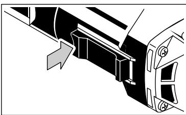
Switching on and off
Switching on: Push the sliding switch forward. To lock, depress the front part of the switch.
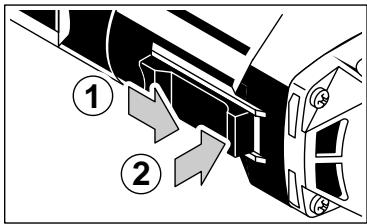
Switching off: To unlock, depress the back part of the sliding switch. The switch will automatically move back to "O".
Dust extraction
Only use the machine with a suitable dust-remover!
Insert the suction hose connector into the adapter until it sits firmly. Connect the other end of the suction hose to a vacuum cleaner which is suited for dust extraction.
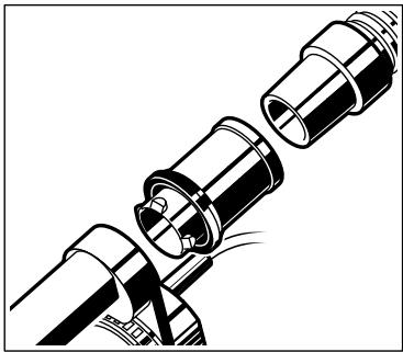
We recommend the use of powerful industrial vacuum cleaners. They are suited for sucking off large quantities of stone dust and allow the machine to be connected directly to the socket of the vacuum cleaner. When the machine is switched on the vacuum cleaner starts automatically.
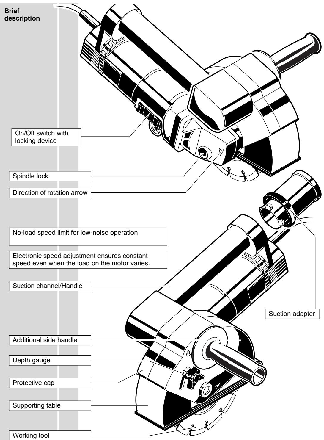
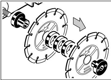
Exchanging the diamond cutting discs
Disassembly

Always disconnect the plug from the socket before carrying out any work on the machine.
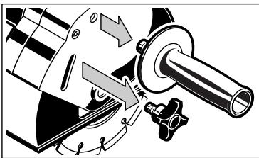
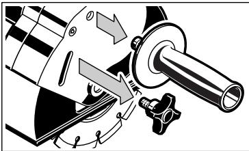
- Remove the auxiliary handle and the machine knob.
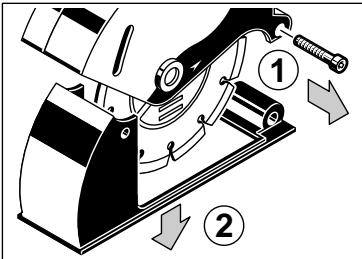
- Screw out screw and take out cutting support downwards.
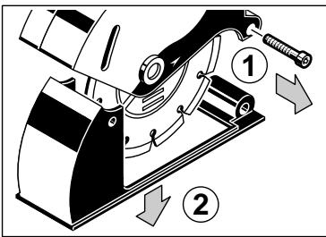
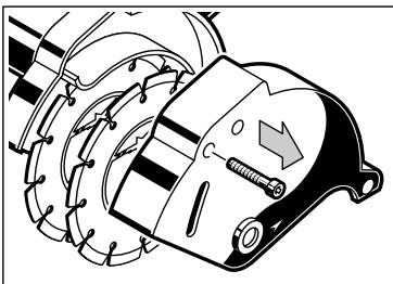
- Screw out screw and take off protective hood cover.
- Lock the work spindle by depressing the spindle lock. Open the flange nut with a pint-type face spanner and remove it.
-
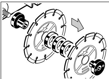
Pull off diamond cutting discs and spacing washers from the bearing flange.
-
Fit the new diamond cutting discs together with the spacing washers and tighten the flange nut with the two hole spanner. Press the shaft stop in to prevent shaft from turning.

The number of spacing washers between the diamond cutting discs determines the cutting width.

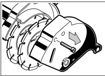
Arrow on diamond cutting discs must agree with arrow on protective hood cover-direction of rotation.

Use the diamond cutting discs appropriate to the type of masonry.
2.
Fit protective hood cover and support guide and set the cutting depth with the star-shaped knob.
Assembly
| Setting the cutting width | The number of spacing washers between the diamond cutting discs determines the cutting width. 1 Spacing washer = approx. 8,0 mm 2 Spacing washers = approx. 11,5 mm 3 Spacing washers = approx. 15,0 mm 4 Spacing washers = approx. 18,5 mm 5 Spacing washers = approx. 22,0 mm 6 Spacing washers = approx. 25,5 mm 1. Demount the diamond cutting discs (see above). 2. Put the according number of distance wash- ers between the diamond cutting discs and flange nut. 3. Reassemble the tool (see above). | |
| Setting the cutting depth | Loosen star-shaped knob slightly and push the cutting support to the desired position. Tighten star-shaped knob again. The cutting depth gets less as the diamond cutting discs wear down. In order to prevent edges from the remaining cut strip breaking out, set the cutting depth slightly deeper. | |
| Advices for operation | Only use the machine for dry cutting in stone. Mind hidden electric lines, gas and water pipes. Check your working area, e.g. with a metal detector. 1. Pre-select the cutting depth and width. 2. Switch the machine on. 3. Set the machine with the front edge of the cutting support touching the masonry and lower it gently in until the cutting support lies flush. 4. Cut the masonry groove by pulling the ma- chine towards you (in direction of arrow in il- lustration), guiding the machine with both hands. Only cut straight lines radii are not possible. Always use the additional handle. When cutting hard material, swing the ma- chine slightly to and fro in the cut then the diamond cutting discs stay sharper longer. 5. When you get to the end of the groove you are cutting, lift the machine out first and then switch off. After switching off, the machine will not be idle immediately. (After-running of the work spindle.) Allow the machine to come to a stop before putting down. The cutting discs get very hot when in use. Do not touch them before they have cooled down. Put the machine down and break out the remaining strip with the paring-out tool. | |
| ENGLISH | 8 | MFE 1305 |
| Tips | Blunt diamond cutting discs are recognisable by the large number of sparks that fly during work, and can be resharpened by making a number of cuts in abrasive material (e.g. plaster).When cutting concrete or brick it is recommended to use only one diamond cutting disk, especially if large cutting depth is required. Otherwise the engine gets over-loaded, and the motor protection device activates the electronic shut-off.If the load-rate motor protection switches the machine off very often, it is possible that the reason for this are power consuming materials like damp or very hard materials. In this case reduce the cutting depth or work with only one diamond cutting disc.If only one disc is fitted it is recommended to use the square between the protective hood cover and cutting support as aid for cutting. For that purpose a spacing washer must be mounted between bearing flange and diamond cutting disk (the remaining spacing washers must be mounted between diamond cutting disk and flange nut). To facilitate this a guide can be mounted to the wall. |
| Service | Keep the machine and the ventilation slots clean.Use only AEG accessories and spare parts. Should components need to be replaced which have not been described, please contact one of our AEG service agents (see our list of guarantee/service addresses).If needed, an exploded view of the tool can be ordered. Please state the ten-digit No. as well as the machine type printed on the label and order the drawing at your local service agents or directly at:Atlas Copco Electric Tools GmbH, Postfach 320, D-71361 Winnenden. |
| Accessories | Please refer to page 2 for range of accessories. Further accessories with part numbers are shown in our catalogues. |
IpepeBbInOpJIHeHnEMKaKx-JIb6o pa60TnoO6CnyXuBaHIO IHCTpyMeHTa BCEgDa BbIHMaIte BUNKy u3 pO3ETKn.
- CHIMITE DoJIoJIHITeIbHyIO pyKoTky.
- BbIbepHnTe BnHT n CHmnte onopy.
- BbIeBpHnTe BnHT n CHIMnTe 3aunTHbI KOxUx.
- 3a6loKpyuTe pa6oHm shnHdIb, Haxab Ha KhoNkY bIoKnpaTopa. OTkpyTnte BnHT KIOHem n CHIMITE erO.
-
CHIMITE C Hecyuero FJlaHca aIMa3HbIe INCKN INPocTABOHyIe IaI6bl.
-
YctaHOBInTe HOBbIe aJIIMa3HbIe IINCKn C pIOCTaBOUHbIMN IaJbAMN N 3aTAHInTe ΦlaHcEByIO rAIky CpeKJIIOyEM.

KolnueCTBO npocTaBOUHbIX 7aM6 MeXy aIma3HbIMN dNcKaMn ONpeJeIeT 7mnpHy wTpo6bl.

CtpeIka Ha aJIma3HbIX OTepe3HbIX DnCKax DoJIxHa COOTBETCTBOBaTc TpeIke Ha 3aUHTHom Koxyxe - yKa3bIbAeT HapabIeHne BpaIeHn.

IoiJIb3yIteCb aIma3HbIMN IINCKAMN COOTBETCTBYIOUIMN TINPy MaTePnAJa KlaIKN.
- YctaHOBInTe 3aunTHbI KOxU n onOpu n OtperyuPny Te rny6nHy npOnmna.
C6opka
EC DECLARATION OF CONFORMITY
We declare under our sole responsibility that this product is in conformity with the following standards or standardization documents: EN 50 144, EN 55 014-1, EN 55 014-2, EN 60 555, HD 400 according to the provisions of the regulations 73/23/EEC, 89/336/EEC, 98/37/EC.
DEUTSCH

Brand : AEG
Model : MFE 1305
Category : Drill