TS 55 E - Drill AEG - Free user manual and instructions
Find the device manual for free TS 55 E AEG in PDF.
| Brand | AEG |
| Model | TS 55 E |
| Product type | Circular saw |
| Rated power | 1500 W |
| No-load speed | 5500 min⁻¹ |
| Saw blade diameter | 160 mm |
| Blade bore | 20 mm |
| Cutting depth at 90° | 55 mm |
| Cutting depth at 45° | 39 mm |
| Weight (without cable) | 5.4 kg |
| Sound pressure level | 93 dB(A) (K=3 dB) |
| Sound power level | 104 dB(A) (K=3 dB) |
| Vibration emission value | 4.7 m/s² (K=1.5 m/s²) |
| Protection class | II (double insulation) |
| Suitable materials | Solid wood, chipboard, plastics, aluminum up to 15 mm |
| Safety | Protective guard, riving knife, mandatory hearing protection |
| Maintenance | Clean ventilation slots with a dry cloth; no oil or grease |
| Spare parts | Available from AEG after-sales service |
| Compliance | EN 60745, directives 2006/42/EC, 2004/108/EC |
Frequently Asked Questions - TS 55 E AEG
User questions about TS 55 E AEG
0 question about this device. Answer the ones you know or ask your own.
Ask a new question about this device
Download the instructions for your Drill in PDF format for free! Find your manual TS 55 E - AEG and take your electronic device back in hand. On this page are published all the documents necessary for the use of your device. TS 55 E by AEG.
USER MANUAL TS 55 E AEG
Original instructions
natural_image
3D rendered mechanical assembly with cutaway view of internal components (no text or symbols visible)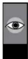
natural_image
Close-up of a mechanical cutterhead with a gear-like blade and central hub, showing no text or symbols.
natural_image
Pure mechanical cross-section diagram without any text, numbers, or symbols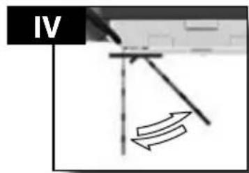

natural_image
Simple line drawing of a wrench with no text or symbols
Accessorio • Acessório Toebehoren • Tilbehør Tilbehør • Tillbehør Lisälaite • Εξαρτήματα Aksesuar • Příslušenství Príslušenství Wyposażenie Azokat a tartozékokat Oprema • Piederumi Priedas • Tarvikud Дополнитель•Аксесоари Accesoriu • ополнителна опрема • 配件
natural_image
Close-up of a mechanical cutting tool with a gear-like blade and circular head (no visible text or symbols)


natural_image
Pure diagram of a mechanical or architectural component with no visible text, numbers, or symbols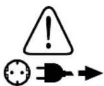
natural_image
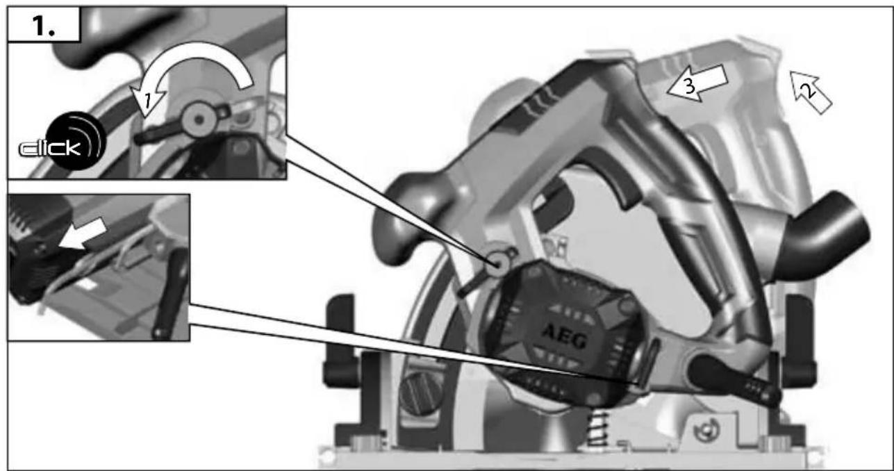
Mechanical device interior view showing internal components and a close-up of a rotary knob (no text or symbols visible)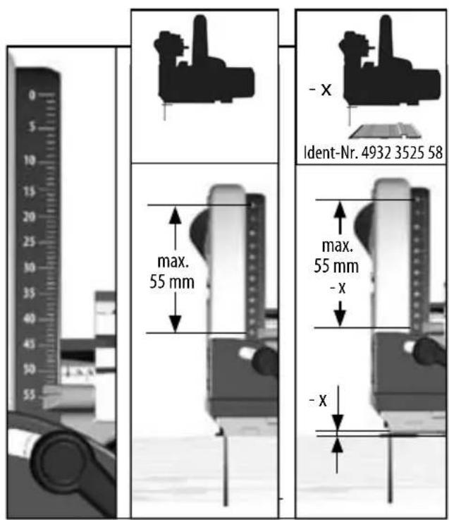
natural_image
Cross-sectional diagram of a mechanical device with internal components and directional arrows (no text or symbols)


natural_image
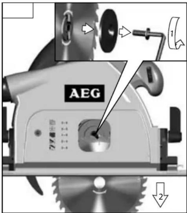
Pure diagram of a mechanical or architectural component with a vertical double-headed arrow indicating width (no text or symbols)
natural_image
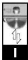
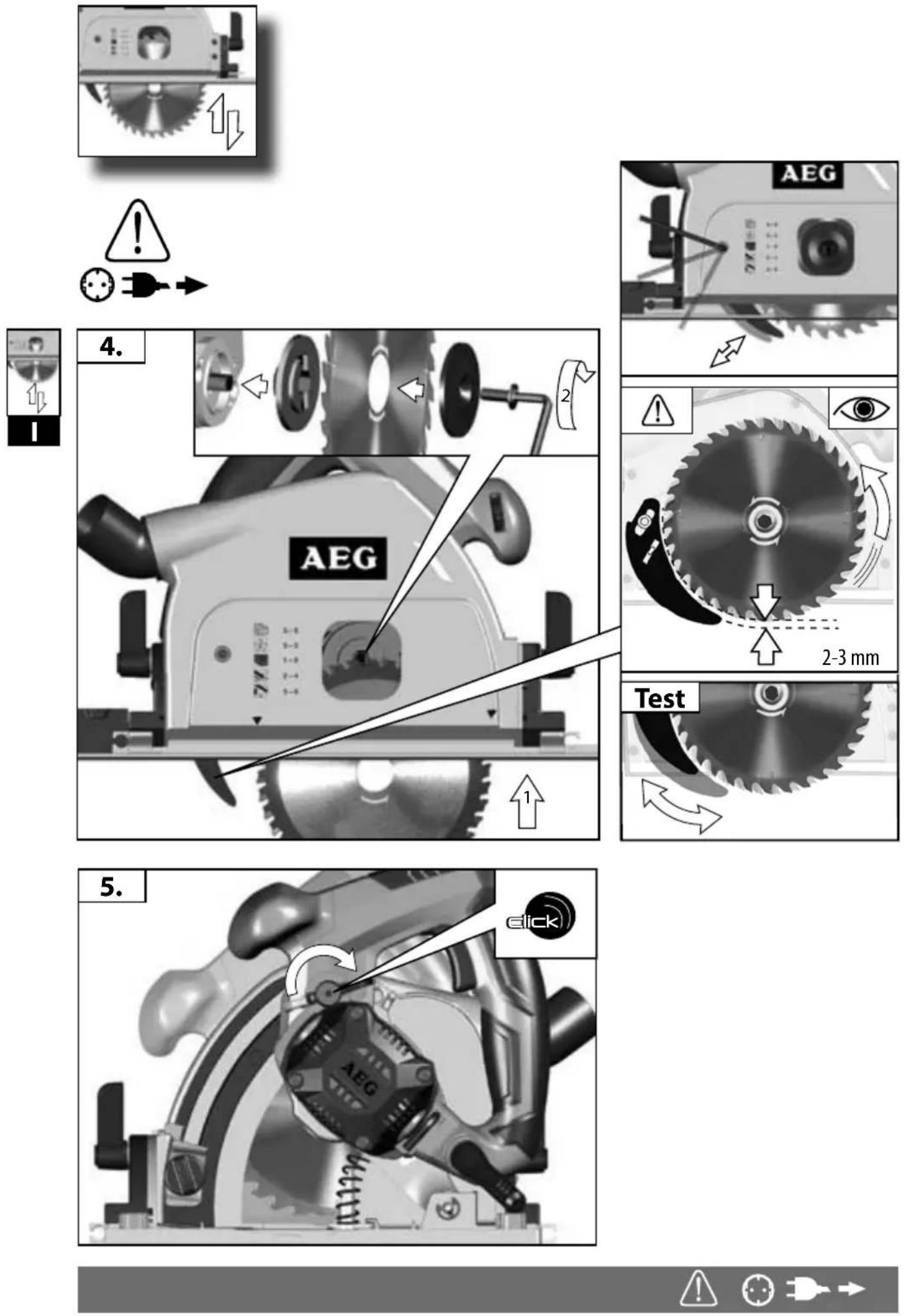
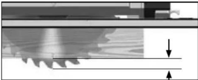
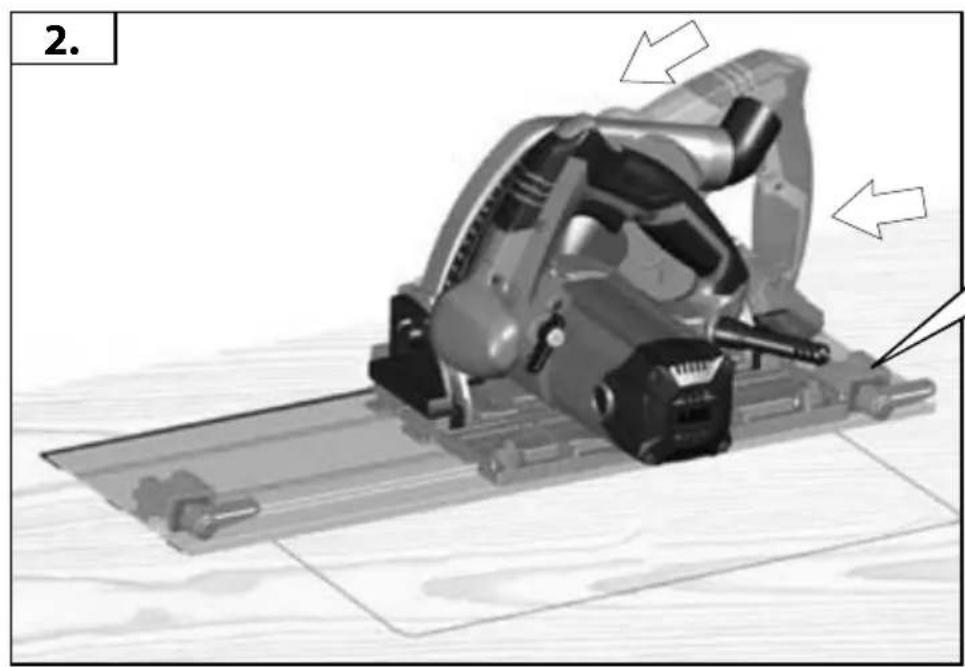
Close-up of a mechanical component with gear teeth and a horizontal bar, showing motion direction arrows (no text or symbols)Adjust the cutting depth to the thickness of the workpiece. Less than a full tooth of the blade teeth should be visible below the workpiece.
natural_image
Pure mechanical component diagram without any text, numbers, or symbolsnatural_image
Pure mechanical diagram showing a lever and curved arrow symbol without any text or labels

natural_image
Pure technical diagram showing a wrench and curved arrow symbol without any text or labels
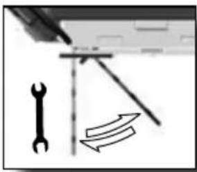
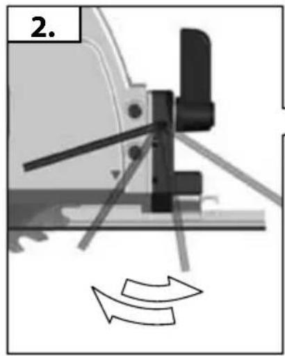
If a correction of the 90° angle of the guide-plate to the saw blade is necessary, use the correction screw.
natural_image
Pure technical diagram showing a wrench and a curved arrow with directional arrows, no text or symbols present.45°


natural_image
Mechanical assembly diagram showing a cutting tool and workpiece (no text or symbols visible)
natural_image
Mechanical component diagram showing a pinwheel with motion arrows indicating rotation (no text or symbols)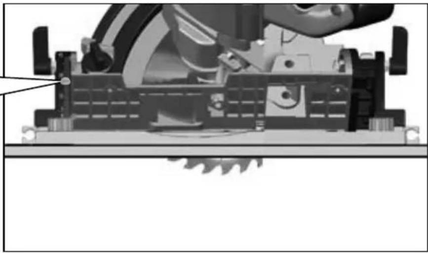
natural_image
Mechanical assembly diagram showing a cutting tool and workpiece (no text or symbols visible)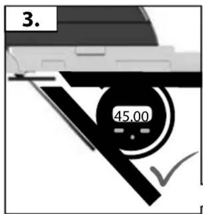
natural_image
Mechanical assembly diagram showing a cutting tool and workpiece (no text or symbols visible)


Accessory
Zubehör
Accessoire
Accessorio
Accessorio
Acessório
Toebehoren
Tilbehør
Tilbehør
Tillbehör
Lisälaite
Εξαρτήματα
Aksesuar
Příslušenství
Príslušenstvo
Element
wyposażenia
dodatkowego
Tartozék
Oprema
Pribor
Papildus
aprikojums
Priedas
Tarvikud
Дополнитель
Аксесоар
Accesorii
Додатоци
配件
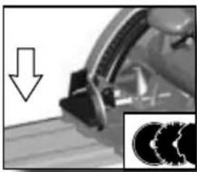
natural_image
Close-up of a mechanical component with a downward arrow and magnified inset showing three circular features (no text or symbols)Accessory
Zubehör
Accessoire
Accessorio
Accessorio
Acessório
Toebehoren
Tilbehør
Tilbehør
Tillbehör
Lisälaite
Εξαρτήματα
Aksesuar
Příslušenství
Príslušenstvo
Element
wyposażenia
dodatkowego
Tartozék
Oprema
Pribor
Papildus
aprikojums
Priedas
Tarvikud
Дополнитель
Аксесоар
Accesorii
Додатоци
配件
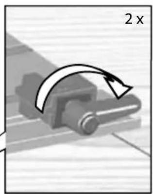
natural_image
Mechanical component with curved arrow indicating 2x increase (no text or symbols)
natural_image
Mechanical assembly diagram showing a cutting tool with arrows indicating motion direction (no text or symbols present)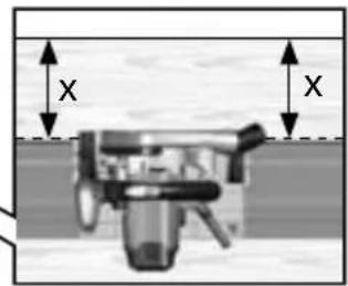
natural_image
Mechanical assembly diagram showing a lever and shaft assembly (no text or symbols visible)
natural_image
Diagram of a particle flow through a funnel with an arrow indicating direction (no text or symbols)

natural_image
Black and white photo of a vacuum cleaner (labeled AP 300 ELCP) with no visible text or symbols on the device itself.
natural_image
Cross-sectional diagram of a mechanical device with no visible text or symbols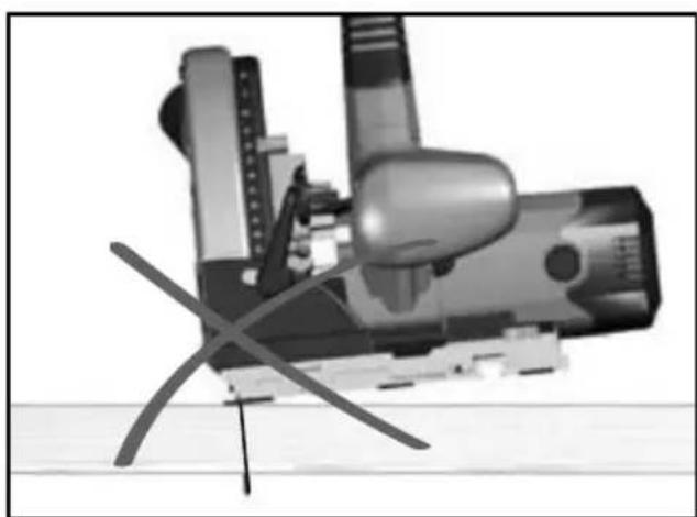
natural_image
Illustration of a helicopter with propellers and control panels (no text or symbols)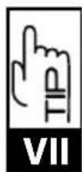
natural_image
Pure mechanical component diagram without any text, numbers, or symbols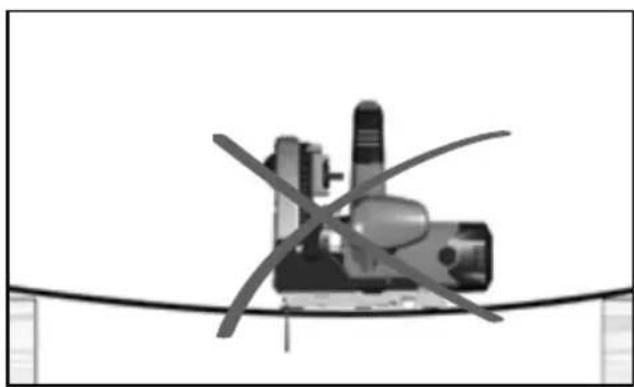
natural_image
Diagram of a mechanical device with intersecting curved lines, no visible text or symbols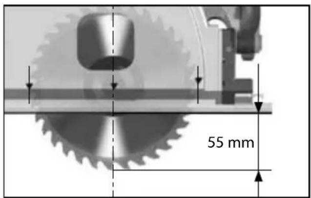
natural_image
Simple line drawing of a wrench (no text or symbols)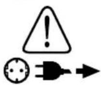
TS 55 E
Rated input 1500 W
No-load speed ....5500 min ^-1
Saw blade dia. x hole dia. 160 x 20 mm
Cutting depth at 45^ .....39 mm
Cutting depth at 90°....55 mm
Weight without cable....5,4 kg
Noise/Vibration Information
Measured values determined according to EN 60 745.
Typically, the A-weighted noise levels of the tool are:
Sound pressure level (K = 3 dB(A)) .....93 dB (A)
Sound power level (K = 3 dB(A)).....104 dB (A)
Wear ear protectors!
Total vibration values (vector sum in the three axes) determined according to EN 60745.
Vibration emission value a_h 4,7 m/s ^2
Uncertainty K = 1,5 m/s ^2
WARNING
The vibration emission level given in this information sheet has been measured in accordance with a standardised test given in EN 60 745 and may be used to compare one tool with another. It may be used for a preliminary assessment of exposure.
The declared vibration emission level represents the main applications of the tool. However if the tool is used for different applications, with different accessories or poorly maintained, the vibration emission may differ. This may significantly increase the exposure level over the total working period.
An estimation of the level of exposure to vibration should also take into account the times when the tool is switched off or when it is running but not actually doing the job. This may significantly reduce the exposure level over the total working period.
Identify additional safety measures to protect the operator from the effects of vibration such as: maintain the tool and the accessories, keep the hands warm, organisation of work patterns.

WARNING!
Read all safety warnings and all instructions, including those given in the accompanying brochure. Failure to follow the warnings and instructions may result in electric shock, fire and/or serious injury. Save all warnings and instructions for future reference.
SAFETY INSTRUCTIONS

Danger:
Keep hands away from cutting area and the blade. Keep your second hand on auxiliary handle, or motor housing. If both hands are holding the saw, they cannot be cut by the blade.
Do not reach underneath the workpiece. The guard cannot protect you from the blade below the workpiece.
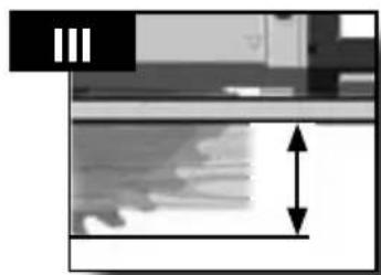
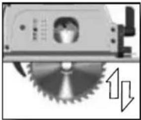
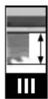
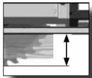
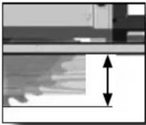
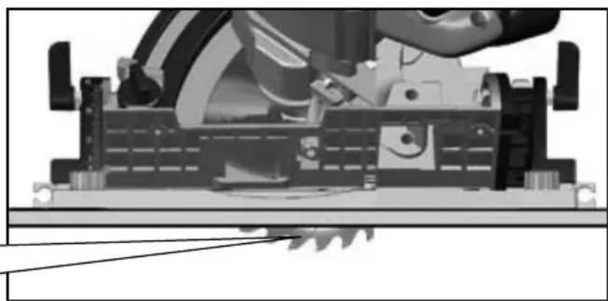
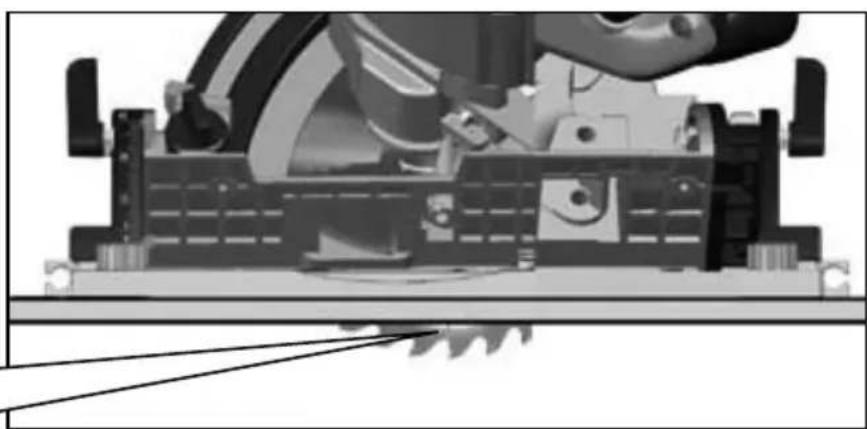
Adjust the cutting depth to the thickness of the workpiece.
Less than a full tooth of the blade teeth should be visible below the workpiece.
Never hold piece being cut in your hands or across your leg. Secure the workpiece to a stable platform. It is important to support the work properly to minimize body exposure, blade binding, or loss of control.
Hold power tool by insulated gripping surfaces when performing an operation where the cutting accessory may contact hidden wiring or its own cord. Cutting accessory contacting a „live“ wire may make exposed metal parts of the power tool „live“ and could give the operator an electric shock.
When ripping always use a rip fence or straight edge guide. This improves the accuracy of cut and reduces the chance of blade binding.
Always use blades with correct size and shape (diamond versus round) of arbour holes. Blades that do not match the mounting hardware of the saw will run eccentrically, causing loss of control.
Never use damaged or incorrect blade washers or bolt. The blade washers and bolt were specially designed for your saw, for optimum performance and safety of operation.
Causes and operator prevention of kickback:
- kickback is a sudden reaction to a pinched, bound or misaligned saw blade, causing an uncontrolled saw to lift up and out of the workpiece toward the operator;
- when the blade is pinched or bound tightly by the kerf closing down, the blade stalls and the motor reaction drives the unit rapidly back toward the operator;
- if the blade becomes twisted or misaligned in the cut, the teeth at the back edge of the blade can dig into the top surface of the wood causing the blade to climb out of the kerf and jump back toward the operator.
Kickback is the result of saw misuse and/or incorrect operating procedures or conditions and can be avoided by taking proper precautions as given below.
Maintain a firm grip with both hands on the saw and position your arms to resist kickback forces. Position your body to either side of the blade, but not in line with the blade.
Kickback could cause the saw to jump backwards, but kickback forces can be controlled by the operator, if proper precautions are taken.
When blade is binding, or when interrupting a cut for any reason, release the trigger and hold the saw motionless in the material until the blade comes to a complete stop. Never attempt to remove the saw from the work or pull the saw backward while the blade is in motion or kickback may occur. Investigate and take corrective actions to eliminate the cause of blade binding.
When restarting a saw in the workpiece, centre the saw blade in the kerf and check that saw teeth are not engaged into the material. If saw blade is binding, it may walk up or kickback from the workpiece as the saw is restarted.
Support large panels to minimise the risk of blade pinching and kickback. Large panels tend to sag under their own weight.
Supports must be placed under the panel on both sides, near the line of cut and near the edge of the panel.
Do not use dull or damaged blades. Unsharpened or improperly set blades produce narrow kerf causing excessive friction, blade binding and kickback.
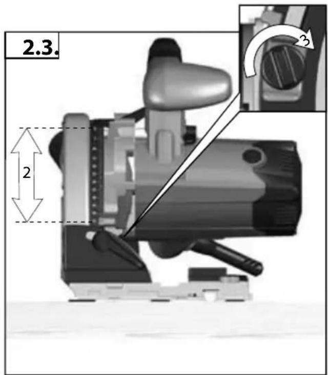
Blade depth and bevel adjusting locking levers must be tight and secure before making cut. If blade adjustment shifts while cutting, it may cause binding and kickback.
Use extra caution when making a „plunge cut“ into existing walls or other blind areas. The protruding blade may cut objects that can cause kickback.
Function of the guard
Check guard for proper closing before each use. Do not operate the saw if guard does not move freely and enclose the blade instantly. Never clamp or tie the guard with the blade exposed. If saw is accidentally dropped, guard may be bent. Check to make sure that guard moves freely and does not touch the blade or any other part, in all angles and depths of cut.
Check the operation and condition of the guard return spring. If the guard and the spring are not operating properly, they must be serviced before use. Guard may operate sluggishly due to damaged parts, gummy deposits, or a build-up of debris.
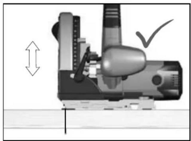
Assure that the guide plate of the saw will not shift while performing the "plunge cut" when the blade bevel setting is not at 90°. Blade shifting sideways will cause binding and likely kick back.
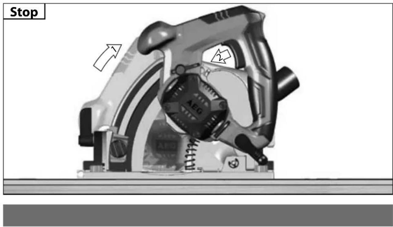
Always observe that the guard is covering the blade before placing saw down on bench or floor. An unprotected, coasting blade will cause the saw to walk backwards, cutting whatever is in its path. Be aware of the time it takes for the blade to stop after switch is released.
Riving knife function
Use the appropriate riving knife for the blade being used. For the riving knife to work, it must be thicker than the body of the blade but thinner than the tooth set of the blade.
Adjust the riving knife as described in this instruction manual. Incorrect spacing, positioning and alignment can make the riving knife ineffective in preventing kickback.
Always use the riving knife, even when „plunge cutting“.
The riving knife is being pressed upwards during plunge cutting and springs back automatically into the kerf after plunge cutting when you move the saw forward.
For the riving knife to work, it must be engaged in the workpiece. The riving knife is ineffective in preventing kickback during short cuts.
Do not operate the saw if riving knife is bent. Even a light interference can slow the closing rate of a guard.
Wear ear protectors. Exposure to noise can cause hearing loss.
Use protective equipment. Always wear safety glasses when working with the machine. The use of protective clothing is recommended, such as dust mask, protective gloves, sturdy non-slip footwear, helmet and ear defenders.
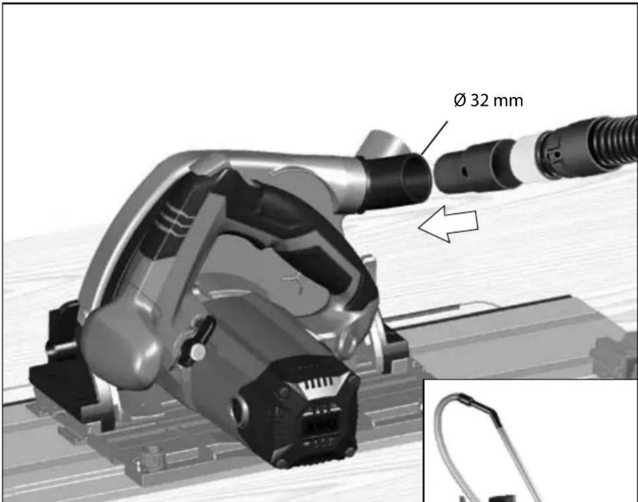
The dust produced when using this tool may be harmful to health. Do not inhale the dust. Use a dust absorption system and wear a suitable dust protection mask. Remove deposited dust thoroughly, e.g. with a vacuum cleaner.
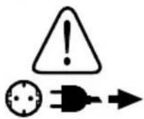
Always disconnect the plug from the socket before carrying out any work on the machine.
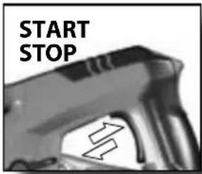
Only plug-in when machine is switched off.
Keep mains lead clear from working range of the machine. Always lead the cable away behind you.
Before use check machine, cable, and plug for any damages or material fatigue. Repairs should only be carried out by authorised Service Agents.
Do not use inserted tools not corresponding to the key data given in these instructions for use.
Please do not use abrasion disks in this machine!
When sawing aluminium, the following measures must be taken for safety reasons:
- Pre-connect a residual current device (FI, RCD, PRCD.
- Connect the machine to a suitable dust extractor.
- Clean the machine regularly of dust deposits in the motor housing and in the protective cover.
- Aluminium must only be sawed with the special saw blades designed for this purpose.
- When sawing panels, they must be lubricated with petroleum, thin-walled profi les (up to 3 mm) can be sawed without lubrication.
SPECIFIED CONDITIONS OF USE
The plungecut circular saw can be used for sawing solid wood, bonded wood, glued veneer, materials similar to wood, plaster and cement-bonded fibre materials, aluminium profiles, Non-ferrous metals and plastics.
Do not use this product in any other way as stated for normal use.
EC-DECLARATION OF CONFORMITY
We declare under our sole responsibility that this product is in conformity with the following standards or standardized documents. EN 60745, EN 55014-1, EN 55014-2, EN 61000-3-2, EN 61000-3-3, in accordance with the regulations 2006/42/EC, 2004/108/EC

Winnenden, 2010-10-25

Rainer Kumpf Manager Product Development Authorized to compile the technical file
MAINS CONNECTION

Connect only to single-phase AC current and only to the system voltage indicated on the rating plate. It is also possible to connect to sockets without an earthing contact as the design conforms to safety class II.
MAINTENANCE
The ventilation slots of the machine must be kept clear at all times.
Clean only with dry cloth. Certain cleaning agents and solvents are harmful to plastics and other insulated parts. Keep the apparatus handle clean, dry and free of oil or grease.
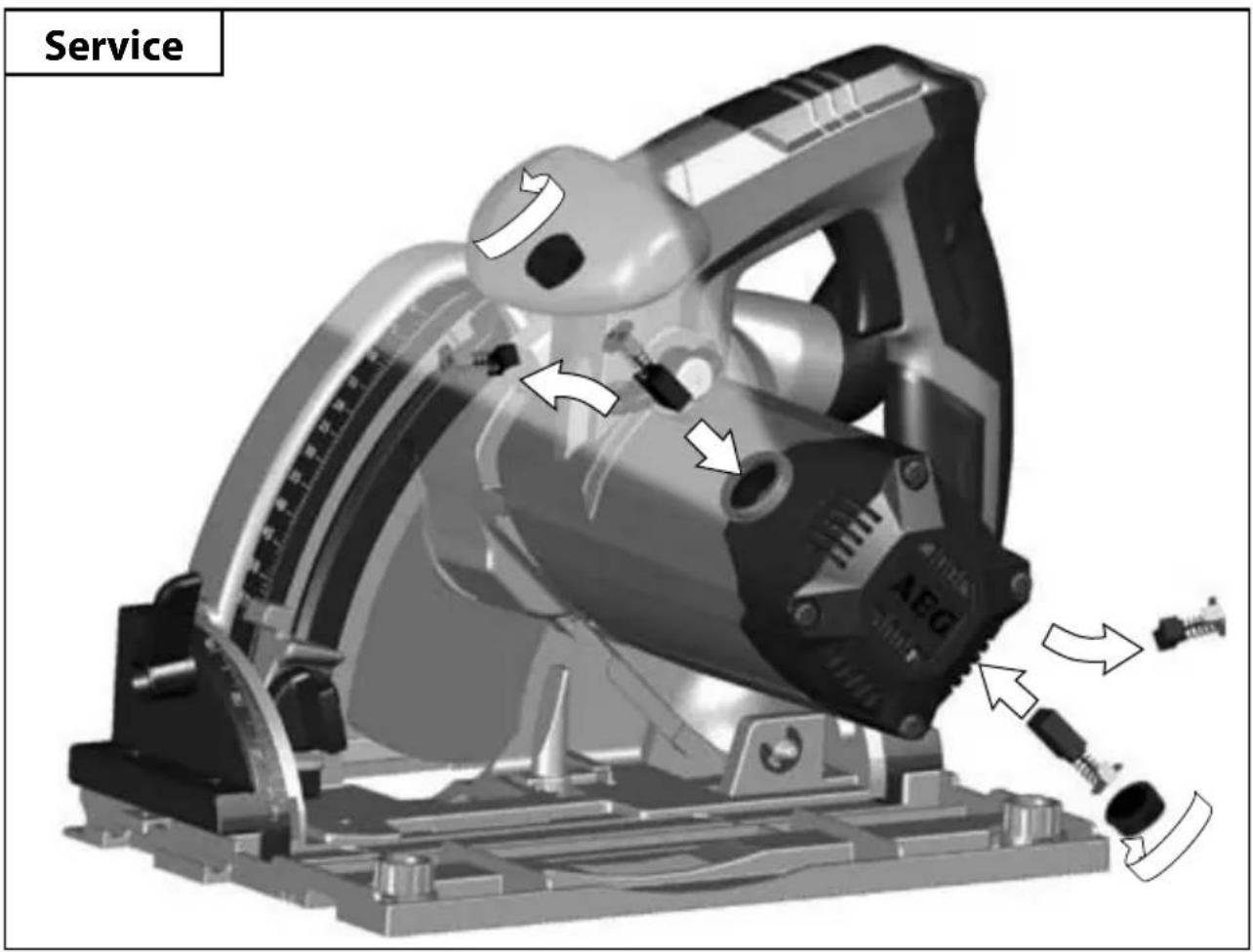
Use only AEG accessories and spare parts. Should components need to be replaced which have not been described, please contact one of our AEG service agents (see our list of guarantee/service addresses). If needed, an exploded view of the tool can be ordered. Please state the Article No. as well as the machine type printed on the label and order the drawing at your local service agents or directly at: AEG Elektrowerkzeuge, Max-Eyth-Straße 10, D-71364 Winnenden, Germany.
SYMBOLS

Please read the instructions carefully before starting the machine.

CAUTION! WARNING! DANGER!

The dust produced when using this tool may be harmful to health. Do not inhale the dust. Wear a suitable dust protection mask.

Always wear goggles when using the machine.

Always disconnect the plug from the socket before carrying out any work on the machine.

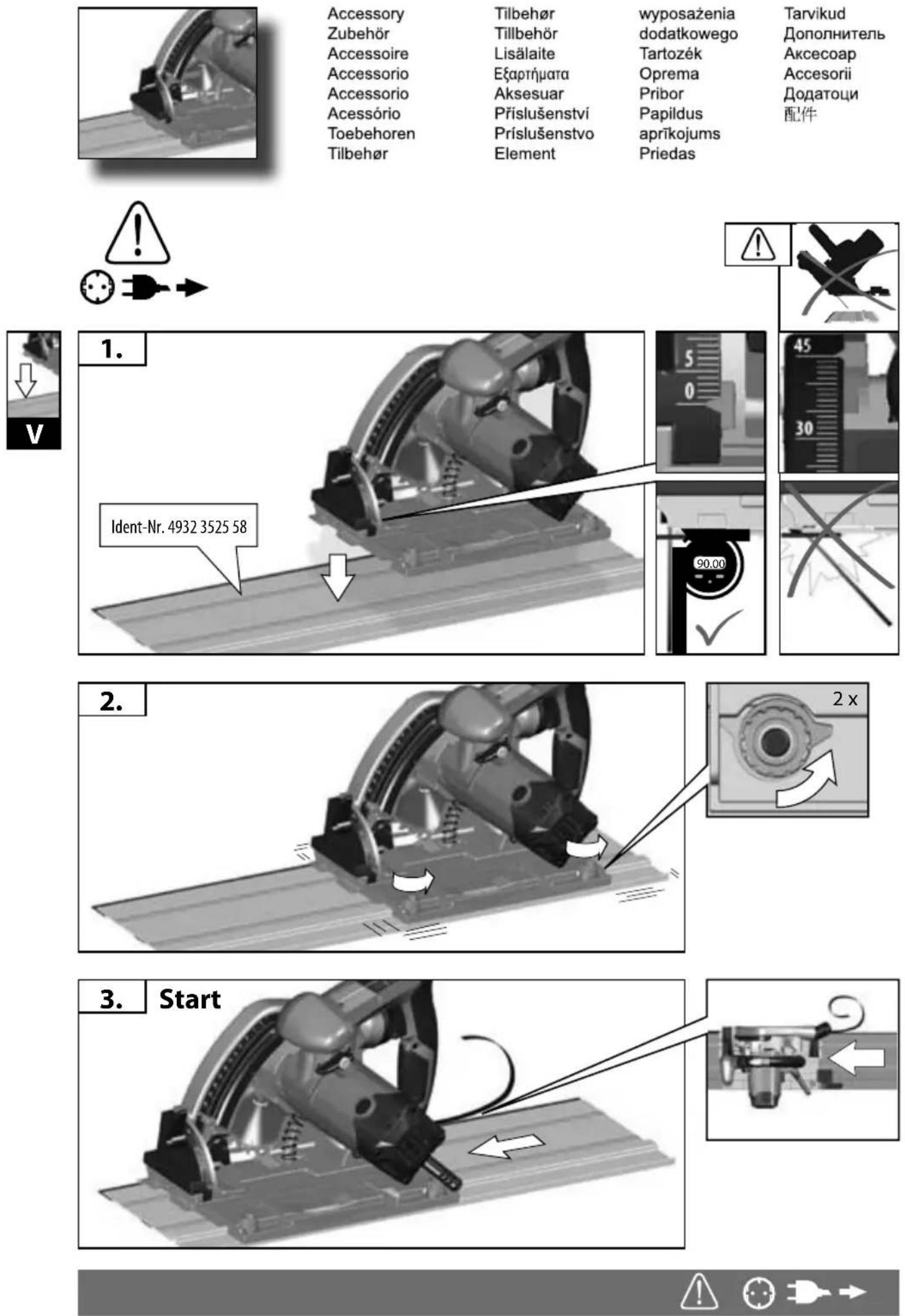
Accessory - Not included in standard equipment, available as an accessory.

Solid wood (hard, soft), chipboards and hard fibre boards, laminated wood, blockboards, veneered and coated boards

Plastics, fibre-reinforced plastics paper and fabric acrylic glass

Plaster and cement-bonded fibre boards

Aluminium panels and profiles up to 15 mm

Do not dispose of electric tools together with household waste material! In observance of European Directive 2002/96/EC on waste electrical and electronic equipment and its implementation in accordance with national law, electric tools that have reached the end of their life must be collected separately and returned to an environmentally compatible recycling facility.
TS 55 E
Winnenden, 2010-10-25
Rainer Kumpf
Manager Product Development
DECLARATION CE DE CONFORMITÉ
Winnenden, 2010-10-25

Rainer Kumpf
Manager Product Development
Winnenden, 2010-10-25
Winnenden, 2010-10-25
Rainer Kumpf
Manager Product Development
Winnenden, 2010-10-25
Rainer Kumpf
Manager Product Development
Winnenden, 2010-10-25
Rainer Kumpf
Manager Product Development
OPGELET! WAARSCHUWING! GEVAAR!

Winnenden, 2010-10-25

Rainer Kumpf
Manager Product Development
Winnenden, 2010-10-25
Rainer Kumpf
Manager Product Development
Winnenden, 2010-10-25
Rainer Kumpf
Manager Product Development
Winnenden, 2010-10-25

Rainer Kumpf
Manager Product Development
Manager Product Development
Winnenden, 2010-10-25
Rainer Kumpf
Manager Product Development
Winnenden, 2010-10-25
Rainer Kumpf
Manager Product Development
CE - VYHLÁSENIE KONFORMITY

Winnenden, 2010-10-25
Winnenden, 2010-10-25
Rainer Kumpf
Manager Product Development
Winnenden, 2010-10-25
UPORABA V SKLADU Z NAMEMBNOSTJO
Winnenden, 2010-10-25

Rainer Kumpf
Manager Product Development
Winnenden, 2010-10-25

Rainer Kumpf
Manager Product Development
Ovlašten za formiranje tehničke dokumentacije.
PRIKLJUČAK NA MREŽU


Winnenden, 2010-10-25
Winnenden, 2010-10-25
Rainer Kumpf
Manager Product Development
lgaliotas parengti techninius dokumentus.
ELEKTROS TINKLO JUNGTIS

SPETSIAALSED TURVAJUHISED

OHUD:
Winnenden, 2010-10-25

Rainer Kumpf
Manager Product Development
Winnenden, 2010-10-25

Rainer Kumpf Manager Product Development
Winnenden, 2010-10-25

Rainer Kumpf
Manager Product Development

Winnenden, 2010-10-25
Winnenden, 2010-10-25

Rainer Kumpf
Manager Product Development