
PN 6000 S - Drill AEG - Free user manual and instructions
Find the device manual for free PN 6000 S AEG in PDF.
| Product type | Rotary pneumatic hammer drill |
| Brand | AEG |
| Model | PN 6000 S |
| Chuck type | SDS-max |
| Power supply | Mains electricity |
| Rated voltage | 230 V |
| Frequency | 50 Hz |
| Power consumption | 1500 W |
| No-load speed | 0 – 800 rpm |
| No-load impact rate | 0 – 4000 impacts/min |
| Impact energy | 8 J |
| Weight | 6 kg |
| Dimensions (L x W x H) | 450 x 100 x 250 mm |
| Functions | Drilling, hammer drilling, chiselling |
| Speed adjustment | Variable by trigger |
| Depth stop | Adjustable |
| Auxiliary handle | Adjustable (front and side) |
| Anti-vibration system | Yes |
| Maintenance | Clean ventilation slots, replace carbon brushes at service center |
| Safety | Disconnect plug before any intervention |
| Warranty | See attached brochure |
| Spare parts | Use only AEG parts |
Frequently Asked Questions - PN 6000 S AEG
User questions about PN 6000 S AEG
0 question about this device. Answer the ones you know or ask your own.
Ask a new question about this device
Download the instructions for your Drill in PDF format for free! Find your manual PN 6000 S - AEG and take your electronic device back in hand. On this page are published all the documents necessary for the use of your device. PN 6000 S by AEG.
USER MANUAL PN 6000 S AEG
natural_image
Technical line drawing of a drill bit with drill bit, no text or symbols presentGB Instructions for use
Please read and save these instructions.
D Gebrauchsanleitung Bitte lesen und aufbewahren.
F Instruction d'utilisation Prière de lire et de conserver.
I Istruzioni d'uso
Si prega di leggere le istruzioni e
di conservarle.
E Instrucciones de uso
Lea y conserve estas
instrucciones por favor.
P Instruções de serviço
Por favor leia e conserve em seu poder.
NL Gebruiksaanwijzing
Lees en let goed op deze adviezen.
DK Brugsanvisning
Vær venlight at læse og opbevare.
s Bruksanvisning
Var god läs och tag tillvara dessa instruktioner.
FIN Käyttöohje
Lue ja säilytö
TR Kullanımkılavuzu
Lütfenokuyunvesaklayin
RUS Инструкцияпо использованию
Пожалуйста, прочтитеи сохранитенастоящую инструкцию
| Introduction | You demand the best and buy quality – quality provided by Atlas Copco.We have built for you a reliable and lasting tool. Working effectively and without endangering your health is only possible if these instructions for use are being read carefully before first using this tool. We want to satisfy our customers and would like you to buy again AEG Electric Power Tools from Atlas Copco. | |
| Technical Data | Nominal power 1020 W....No-load speed 0–550.min....Speed under load max. 0–420 min..Rate of percussion under load max. 31.30 min....Drilling capacity in Concrete 38 mm....concrete with core drill 150 mm....Weight 7,9 kg.... | |
| Advice for your safety | ■Please note safety instructions on red sheet 4000 3330 24!■Dust that arises when working on material containing asbestos or stonework containing crystalline silicic acid is harmful to the health. Please follow accident prevention regulations.■Appliances used at many different locations including open air must be connected via a current surge preventing switch.■Always wear goggles when using the machine. It is recommended to wear gloves, sturdy non slipping shoes and apron.■Sawdust and splinters must not be removed while the machine is running.■Do not pierce the motor housing as this could damage the double insulation (use adhesives).■Always disconnect the plug from the socket before carrying out any work on the machine.Only plug-in when machine is switched off.■Keep mains lead clear from working range of the machine. Always lead the cable away behind you.■Always use the additional handle, even if the machine has a safety clutch since this safety clutch only engages when the machine blocks with a jerk.■When drilling in walls ceiling, or floor, take care to avoid electric cables and gas or waterpipes. | |
| Measured sound value | Typically the A-weighted noise levels of the tool are:Sound pressure level = 91 dB (A).Sound power level = 104 dB (A).Wear ear protectors! | |
| Measured vibration value | Typically the weighted acceleration is 5,8 m/s^2 . | |
| Usage | The pneumatic hammer can be universally used for hammer drilling and chiselling in stone.Do not use this product in another way as stated for normal use. | |
| Mains connection | Connect only to a single-phase AC current supply and only to the mains voltage specified on the rating plate. Connection to sockets without earth protection is possible as the appliance features protective insulation to DIN 57 740/ VDE 0740 and CEE 20. Radio suppression complies with the European standard EN 55014.When fitting the plug, make sure that the brown (live) wire of this appliance is connected to the plug terminal marked L or coloured red, and the blue (neutral) wire of this appliance is connected to the plug terminal marked N or coloured black.Under no circumstances must the wires of this appliance be connected to the earth terminal of the plug marked either E, with the earth symbol or coloured green or green/yellow. | |
| ENGLISH | 1 | PNEUMATIC 6000 S |
Modifications: Text, diagrams and data are correct at the time of printing. In the interest of continuous improvement of our products, technical specifications are subject to alteration without prior notice.
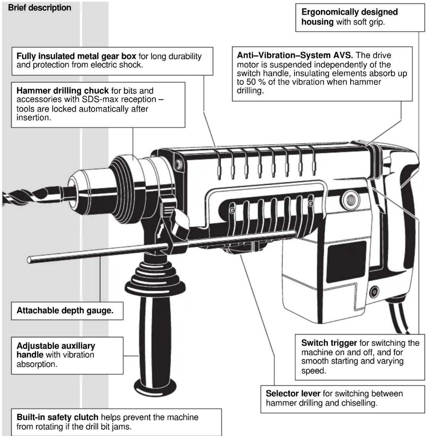
Function of rotary pneumatic hammer
The impact needed for hammer drilling in stone is created by a pneumatic hammer striking mechanism. Similar to hitting a common chisel with a hammer, a plunger hits the axially moving chisel. The electric motor moves the plunger back and forth crank drive -> piston -> freely moving piston. There is a pneumatic cushion between piston and freely moving piston (pneumatic hammer mechanism). This results in a highly effective hammering action.
Exerting greater power does not increase the machine's effectiveness.
| Inserting hammer drill bit or chisel |  | Always disconnect the plug from the socket before carrying out any work on the machine. | ||
| The following tools can be inserted in the drill-hammer chuck using the SDS-max shank: -Hammer-drill for concrete and brickwork -Pointed chisel, flat chisel, hollow chisel, tile chisel -Adapter for geared drill chuck or Only use accessories with SDS-max shank! | ||||
| Inserting tools | 1. | Clean and grease the shank of the bit. | ||
| 2. | Push bit into chuck turning it lightly, the chuck locks the bit in to the chuck automatically. | |||
| 3. | Check that the bit is properly locked into place. It must be possible to move it back and forth. | 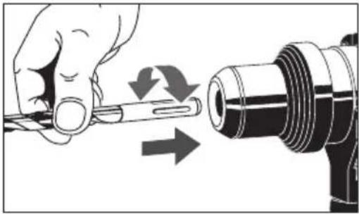 | ||
| Tool removal | 4. | Pull back plastic ring in direction of arrow and remove bit. | 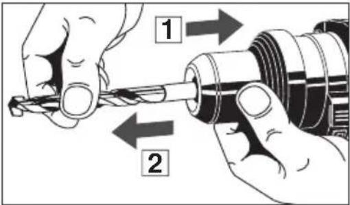 | |
| Switching between hammer drilling, chiselling | Depending on the inserted tool the machine can be operated with additional rotation (SDS-max-drills) or without additional rotation (SDS-max-chisels). For additional rotation turn the dial accordingly. | |||
| hammer drilling rotary stop (chiselling) adjusting position spindle locking position | ||||
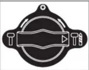 | 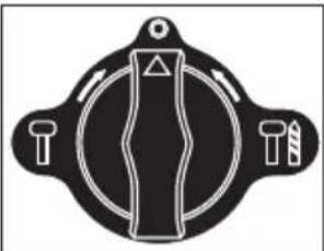 | 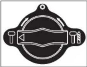 | ||
 | In "adjusting position" the chisel can be turned by hand to the required angle. Afterwards lock the spindle with the selector lever while turning the chisel slightly. To help the lever lock into position twist the inserted bit slightly when switching gears. Do not switch when the machine is under load. | |||
 | During no-load operation the pneumatic hammer mechanism is not yet activated even if the hammer mechanism is switched on. A safety device suppress the snap die from idle stroking on the tool used (hammer drill/chisel). To activate the pneumatic hammer mechanism all you have to do is to firmly push the running machine against the working material. This unlocks the snap die from the safety device, and drilling with light pressure is now possible. | |||
| ENGLISH | 3 | PNEUMATIC 6000 S |
| On-off switch | Switching on: Press on-off switchSwitching off: Release on-off switchThe speed can be infinitely varied by pressing the On-/Off switch. | 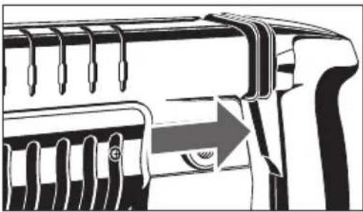 | |
| Depth gauge | The depth gauge can be attached either to the right or to the left hand side of the auxiliary handle. Push the depth gauge holder into the auxiliary handle until the locking mechanism engages. To remove the depth gauge depress the locking mechanism and remove the depth gauge from the handle.For drilling identical depths insert the depth gauge into the boring of the depth gauge holder, push it back by the required drilling depth and fasten it. | 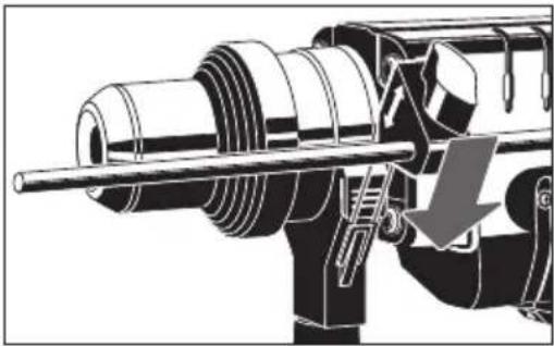  | |
| Handle | In order to twist the additional handle loosen it as shown in illustration and move to the required position. Refasten additional handle.The auxiliary handle can also be attached to the side of the housing. This position should be preferred when drilling into the floor or into the ceiling, for example.Remove the auxiliary handle from the front position and screw it down at the side of the machine. | 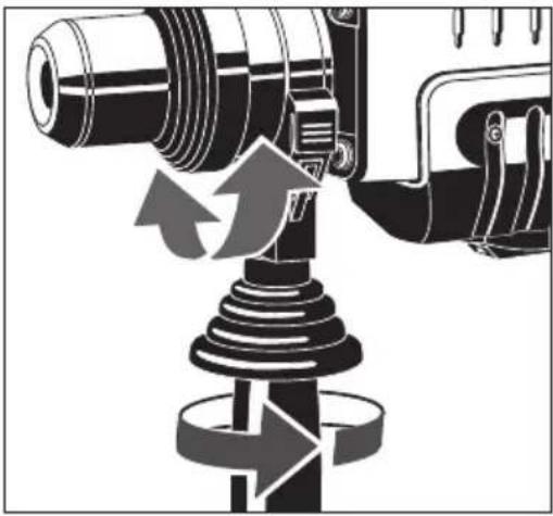 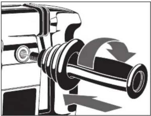 | |
| ENGLISH | 4 | PNEUMATIC 6000 S |
| Advices for operation | Exerting greater pressure does not increase the machine's effectiveness!The Anti-Vibration-System will work at an optimum when normal working pressure is applied; the shock absorber is then only slightly pressed together.If the applied working pressure is too high, the shock absorber is strongly pushed together and the vibrations are noticeably transmitted to the handle. | |
| Hints | Take the drill out of the hole from time to time to remove dust.Switch to percussion-drilling for concrete, hard bricks and tiles, stone, hard cement, and marble (but not when drilling the surface of marble).For tiles, paving-stones, soft bricks and tiles, soft cement, breeze-block and plaster, switch to normal drilling.Use percussion carbide tipped masonry drill-bits.When drilling a hard, smooth surface (e.g. tiles), cover the point to be drilled with adhesive tape in order to prevent the drill bit tip from skidding. | |
| Maintenance | Should the hammer action deteriorate send it to one of our Service Stations.The ventilation slots of the machine must be kept clear at all times.The machine is fitted with carbon brush that automatically switch it off if they are worn, before the motor can be damaged.If the carbon brushes cut-out or the hammer capacity declines please contact your authorized AEG service station. This will ensure long service life as well as constant readiness for working of the machine.The location of your neerest service station is shown in our “Service adresses” leaflet attached to each product.Use only AEG accessories and spare parts. Should components need to be replaced which have not been described, please contact one of our AEG service agents (see our list of guarantee/service addresses).If needed, an exploded view of the tool can be ordered. Please state the ten-digit No. as well as the machine type printed on the label and order the drawing at your local service agents or directly at: Atlas Copco Elektrowerkzeuge GmbH, Postfach 320, D-71361 Winnenden. | |
| Accessories | The range of accessories with part numbers is shown in our catalogue. | |
| ENGLISH | 5 | PNEUMATIC 6000 S |
EC-DECLARATION OF CONFORMITY
We declare under our sole responsibility that this product is in conformity with the following standards or standardized documents. EN 50144, EN 55104, EN 55014, EN 61000-1, HD 400 in accordance with the regulations 89/392/EEC, 73/23/EEC, 89/336/EEC
DEUTSCH
DÉCLARATION "CE" DE CONFORMITÉ
D-71361 Winnenden Germany
http://www.atlascopco.de
K-01 (03.98) AC 4000 3335 47 MW 58-13-5530
Brand : AEG
Model : PN 6000 S
Category : Drill