
GPL 5 Professional - Rangefinder BOSCH - Free user manual and instructions
Find the device manual for free GPL 5 Professional BOSCH in PDF.

 FR
FR
 BG
BG
 CS
CS
 DA
DA
 DE
DE
 EL
EL
 EN
EN
 ES
ES
 ET
ET
 FI
FI
 HU
HU
 ID
ID
 IT
IT
 KK
KK
 KO
KO
 LT
LT
 LV
LV
 MK
MK
 NL
NL
 NO
NO
 PL
PL
 PT
PT
 RO
RO
 RU
RU
 SK
SK
 SL
SL
 SV
SV
 TH
TH
 TR
TR
 UK
UK
 VI
VI
 ZH
ZH
| Product Type | Laser Distance Measurer |
| Brand | Bosch |
| Model | GPL 5 Professional |
| Maximum Range | 30 meters |
| Measurement Accuracy | ± 2 mm |
| Power Supply | 2 AA batteries (1.5 V) |
| Dimensions (L x W x H) | 100 x 60 x 30 mm |
| Weight (with batteries) | Approx. 200 g |
| Main Functions | Distance measurement, addition, subtraction, continuous measurement, last measurements memory |
| Laser Class | Class 2 (visible laser, wavelength 635 nm) |
| Maintenance and Cleaning | Clean with a soft, dry cloth; do not use harsh chemicals |
| Safety | Do not direct the beam toward eyes; avoid reflection off shiny surfaces |
| Spare Parts and Repairability | Standard AA batteries, carrying strap, optional protective case |
| General Information | Professional device, dust and splash water resistant (IP54) |
Frequently Asked Questions - GPL 5 Professional BOSCH
User questions about GPL 5 Professional BOSCH
0 question about this device. Answer the ones you know or ask your own.
Ask a new question about this device
Download the instructions for your Rangefinder in PDF format for free! Find your manual GPL 5 Professional - BOSCH and take your electronic device back in hand. On this page are published all the documents necessary for the use of your device. GPL 5 Professional by BOSCH.
USER MANUAL GPL 5 Professional BOSCH
natural_image
3D rendered image of a Bosch industrial control box (no visible text or symbols)
Robert Bosch Power Tools GmbH
70538 Stuttgart
GERMANY
www.bosch-pt.com
1609 92A 4HT (2019.01) T/184

1 609 92A 4HT
GPL 5 Professional

BOSCH
In Original Literature, telomati
a. Ojiratiščne (te) na pl instrukcia nominalna
to inst. dequim original
bg Originalna инструкция
The following table is in English:
הכלה
All instructions must be read and observed in order for the measuring tool to function safely. The safeguards integrated into the measuring tool may be compromised if the measuring tool is not used in accordance with these instructions. Never make warning signs on the measuring tool unrecognisable. SAVE THESE INSTRUCTIONS FOR FUTURE REFERENCE AND INCLUDE THEM WITH THE MEASURING TOOL WHEN TRANSFERRING IT TO A THIRD PARTY.
▶ Warning! If operating or adjustment devices other than those specified here are used or other procedures are carried out, this can lead to dangerous exposure to radiation.
The measuring tool is delivered with a warning label (marked in the illustration of the measuring tool on the graphics page).
▶ If the text on the warning label is not in your native language, cover it with the label supplied, which is in your language, before initial commissioning.

Do not direct the laser beam at persons or animals and do not look directly into the laser beam or at its reflection. Doing so could lead to blindness, or could cause accidents or damage to the eyes.
▶ If laser radiation hits your eye, you must close your eyes and immediately turn your head away from the beam.
▶ Do not make any modifications to the laser equipment.
▶ Do not use the laser goggles as protective goggles. The laser goggles make the laser beam easier to see; they do not protect you against laser radiation.
▶ Do not use the laser goggles as sunglasses or while driving. The laser goggles do not provide full UV protection and impair your ability to see colours.
▶ Have the measuring tool serviced only by a qualified specialist using only original replacement parts. This will ensure that the safety of the measuring tool is maintained.
▶ Do not let children use the laser measuring tool unsupervised. They could accidentally dazzle someone.
▶ Do not use the measuring tool in explosive atmospheres which contain flammable liquids, gases or dust. Sparks may be produced inside the measuring tool, which can ignite dust or fumes.

Keep the measuring tool and the holder away from cardiac pacemakers. The magnets inside the measuring tool and the holder generate a field that can impair the function of pacemakers.
▶ Keep the measuring tool and the holder away from magnetic data storage media and magnetically sensitive devices. The effect of the magnets inside the measuring tool and the holder can lead to irreversible data loss.
Product Description and Specifications
Please observe the illustrations at the beginning of this operating manual.
Intended Use
The measuring tool is intended for determining and checking horizontal and vertical lines and plumb points. The measuring tool is suitable for indoor and outdoor use.
Product features
The numbering of the product features shown refers to the illustration of the measuring tool on the graphic page.
(1) Laser beam outlet aperture
(2) On/off switch
(3) Locking mechanism of the battery compartment cover
(4) Battery compartment cover
(5) Serial number
(6) 1/4" tripod mount
(7) Laser warning label
(8) Holder
(9) Locking screw of the holder
(10) Screw hole of the holder
(11) Magnet
(12) Opening for strap attachment
(13) 5/8" tripod mount on holder
(14) 1/4" tripod mount on holder
(15) Measuring plate with foot ^A)
(16) Tripod ^A)
(17) Laser viewing glasses ^4
(18) Protective bag
A) Accessories shown or described are not included with the product as standard. You can find the complete selection of accessories in our accessories range.
Technical data
| Point Laser GPL 5 | |
| Article number | 3 601 K66 2.. |
| Working rangeA) | 30 m |
| Levelling accuracy ±0.3 mm/m | |
10 | English
Point Laser GPL 5
| Self-levelling range (typical) along the | |
| – longitudinal axis ±5° | |
| – lateral axis ±3° | |
| Typical levelling time <4 s | |
| Operating temperature -10 °C to +40 °C | |
| Storage temperature -20 °C to +70 °C | |
| Max. altitude 2000 m | |
| Relative air humidity max. 90 % | |
| Pollution degree according to IEC 61010-1 | 28) |
| Laser class 2 | |
| Laser type 635 nm, <1 mW | |
| C_6 | 1 |
| Divergence 0.8 mrad (full angle) | |
| Tripod mount 1/4" | |
| Batteries 3 × 1.5 V LR6 (AA) | |
| Approx. operating time 24 h | |
| Weight according to EPTA-Procedure 01:2014 | 0.25 kg |
| Dimensions (length × width × height) | 104 × 40 × 80 mm |
| Protection rating IP 5X | |
A) The working range may be reduced by unfavourable environmental conditions (e.g. direct sunlight).
B) Only non-conductive deposits occur, whereby occasional temporary conductivity caused by condensation is expected.
The serial number (5) on the type plate is used to clearly identify your measuring tool.
Fitting
Inserting/Changing the batteries
It is recommended that you use alkaline manganese batteries to operate the measuring tool.
To open the battery compartment cover (4), turn the locking mechanism (3) clockwise to position 🔒 and remove the battery compartment cover. Insert the batteries.
When inserting the batteries, ensure that the polarity is correct according to the illustration on the inside of the battery compartment.
To close the battery compartment cover (4), insert it below the housing and then press it upwards into place. Turn the locking mechanism (3) anticlockwise to position ⚙ to lock the battery compartment cover in place.
If the batteries are running low, the laser beams will flash slowly. The measuring tool can be operated for approx. 8 hours after the flashing starts.
Always replace all the batteries at the same time. Only use batteries from the same manufacturer and which have the same capacity.
▶ Take the batteries out of the measuring tool when you are not using it for a prolonged period of time. The batteries can corrode and self-discharge during prolonged storage.
Operation
Start-up
▶ Protect the measuring tool from moisture and direct sunlight.
▶ Do not expose the measuring tool to any extreme temperatures or variations in temperature. For example, do not leave it in a car for extended periods of time. In case of large variations in temperature, allow the measuring tool to adjust to the ambient temperature before putting it into operation. The precision of the measuring tool may be compromised if exposed to extreme temperatures or variations in temperature.
▶ Avoid substantial knocks to the measuring tool and avoid dropping it. Always carry out an accuracy check before continuing work if the measuring tool has been subjected to severe external influences (see "Accuracy Check of the Measuring Tool", page 11).
▶ Switch the measuring tool off when transporting it.
The pendulum unit is locked when the tool is switched off, as it can otherwise be damaged by big movements.
Switching On/Off
To switch on the measuring tool, push the on/off switch (2) upwards so that "I" is indicated on the switch. Immediately after switching on, the measuring tool sends a laser beam out of each outlet aperture (1).
▶ Do not direct the laser beam at persons or animals and do not stare into the laser beam yourself (even from a distance).
To switch off the measuring tool, push the on/off switch (2) downwards so that "0" is indicated on the switch. The pendulum unit is locked when the tool is switched off.
▶ Never leave the measuring tool unattended when switched on, and ensure the measuring tool is switched off after use. Others may be blinded by the laser beam.
Setting the automatic switch-off
The measuring tool automatically switches itself off after 20 min of operation.
The automatic switch-off can be set from 20 minutes to eight hours. For this, switch the measuring tool on, then immediately off, and then on again within 4 s. To confirm the change, all laser beams will flash quickly for 2 s after switching on the second time.
When switching on the measuring tool the next time, the automatic switch-off is set to 20 minutes again.
Automatic Levelling
Position the measuring tool on a level, firm surface or attach it to the holder (8) or the tripod (16).
After switching on, the automatic levelling function automatically compensates irregularities within the self-levelling range from ±5^ (longitudinal axis) and ±3^ (lateral axis). The levelling is finished as soon as the laser beams do not move any more.
If automatic levelling is not possible, e.g. because the surface on which the measuring tool stands deviates by more than 5^/3^ from the horizontal plane, the laser beams will flash quickly.
If this is the case, set up the measuring tool in a level position and wait for the self-levelling to take place. As soon as the measuring tool is within the self-levelling range of ±5/±3^ , the laser beams will light up continuously.
In case of ground vibrations or position changes during operation, the measuring tool is automatically levelled again. After each levelling process, check the position of the horizontal and/or vertical laser beams in relation to the reference points to avoid errors arising from a change in the measuring tool's position.
Accuracy Check of the Measuring Tool
Influences on Accuracy
The largest influence is exerted by the ambient temperature. In particular, temperature differences that occur from the ground upwards can refract the laser beam.
Since the temperature stratification is greatest at ground level, you should always mount the measuring tool on a tripod for measuring distances of 20 m or more. In addition, position the measuring tool in the centre of the work surface, wherever this is possible.
In addition to external influences, device-specific influences (e.g. falls or heavy impacts) can also lead to deviations. For this reason, check the levelling accuracy each time before beginning work.
When the levelling accuracy of the horizontal laser beams for the longitudinal and lateral axis is within the maximum allowable deviation, then the levelling accuracy for the plumb beams (vertical axis) is thus also checked.
Should the measuring tool exceed the maximum deviation during one of the tests, please have it repaired by a Bosch after-sales service.
Checking the horizontal levelling accuracy of the longitudinal axis
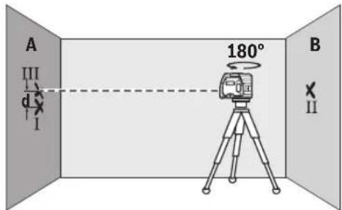
For this check, you will need a free measuring distance of 20 m on firm ground between two walls (designated A and B).
- Mount the measuring tool close to wall A on the holder or a tripod, or place it on a firm, level surface. Switch on the measuring tool.

- Aim the horizontal laser beam that runs parallel to the longitudinal axis of the measuring tool at the closer wall A and allow the measuring tool to level in. Mark the centre of the laser point on the wall (point I).

- Turn the measuring tool 180^ , allow it to level in and mark the centre point of the laser beam on the opposite wall B (point II).
- Position the measuring tool – without rotating it – close to wall B, switch it on and allow it to level in.

- Align the height of the measuring tool (using the tripod or by placing objects underneath as required) so that the centre point of the laser beam exactly hits the previously marked point II on wall B.
12 | English
- Turn the measuring tool 180^ without adjusting the height. Allow it to level in, then mark the centre point of the laser beam on wall A (point III). Ensure that point III is as vertical as possible above or below point I. - The discrepancy d between the two marked points I and III on wall A reveals the actual height deviation of the measuring tool along the longitudinal axis.
The maximum permitted deviation on the measuring distance of 2 × 20 m = 40 m is as follows:
40 m × ±0.3 mm/m = ±12 mm. The discrepancy d between points I and III must therefore amount to no more than 12 mm.
Checking the Horizontal Levelling Accuracy of the Transverse Axis
For this check, you will need a free measuring distance of 20 m on firm ground in front of a wall.
- Mount the measuring tool 20 m from the wall on the holder or a tripod, or place it on a firm, level surface. Switch on the measuring tool.

- Aim one of the two side laser beams that run along the transverse axis of the measuring tool at the wall. Allow the measuring tool to level in. Mark the centre of the laser point on the wall (point I).
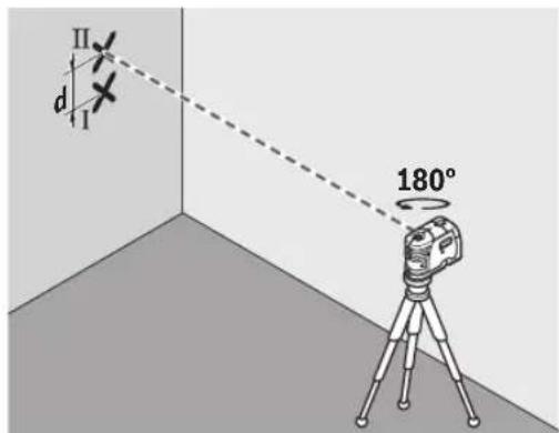
- Turn the measuring tool 180^ without adjusting the height. Allow it to level in, then mark the centre point of the other side laser beam on the wall (point II). Ensure that point II is as vertical as possible above or below point I.
- The discrepancy d between the two marked points I and II on the wall reveals the actual height deviation of the measuring tool along the transverse axis.
The maximum permitted deviation on the measuring distance of 2 × 20 m = 40 m is as follows:
40 m × ±0.3 mm/m = ±12 mm. The discrepancy d between points I and II must therefore amount to no more than 12 mm.
Practical Advice
▶ Always use the centre of the laser point for marking. The size of the laser point changes with the distance.
Working with the measuring plate (accessory)
The measuring plate (15) can be used to project the laser mark onto the ground and/or the laser height onto a wall.
The offset to the desired height can be measured using the zero field and the scale, and can be projected at another point. This means that you do not need to precisely adjust the measuring tool for the height you want to project.
The measuring plate (15) has a reflective coating that enhances the visibility of the laser beam at greater distances and in intense sunlight. The brightness intensification can only be seen if you view the measuring plate with your line of sight parallel to the laser beam.
Working with the Tripod (Accessory)
A tripod offers a stable, height-adjustable support surface for measuring. Place the measuring tool with the 1/4" tripod mount (6) on the thread of the tripod (16) or a conventional camera tripod. Tighten the measuring tool using the locking screw of the tripod.
Roughly align the tripod before switching on the measuring tool.
Attaching using the holder
To attach the measuring tool to the holder (8), tighten the locking screw (9) of the holder in the 1/4" tripod mount (6) so that it is fixed to the measuring tool. Roughly align the holder before switching on the measuring tool.
To turn the measuring tool on the holder (8), loosen the locking screw (9) slightly.
- Rotate the measuring tool on the holder (8) sideways or towards the rear to make the bottom plumb beam visible.
- Rotate the measuring tool on the holder (8) to project heights with the horizontal laser beam.
With the holder (8), the measuring tool can be attached as follows:
- Mount the holder (8) to the tripod (16) or a commercially available camera tripod via the 1/4" tripod mount (14). Use the 5/8" tripod mount (13) to secure the measuring tool on a commercially available building tripod.
- The holder (8) can be attached to steel parts using the magnets (11).
- The holder (8) can be attached to dry construction walls or wooden walls using screws. To do this, insert screws of a length of at least 60 mm through the screw holes (10) of the holder.
- The holder (8) can also be fastened to pipes or similar beams using a commercially available strap by threading it through the opening for the strap attachment (12).
Laser Viewing Glasses (Accessory)
The laser viewing glasses filter out ambient light. This makes the light of the laser appear brighter to the eye.
▶ Do not use the laser goggles as protective goggles. The laser goggles make the laser beam easier to see; they do not protect you against laser radiation.
▶ Do not use the laser goggles as sunglasses or while driving. The laser goggles do not provide full UV protection and impair your ability to see colours.
Maintenance and Servicing
Maintenance and Cleaning
Keep the measuring tool clean at all times.
Never immerse the measuring tool in water or other liquids. Wipe off any dirt using a damp, soft cloth. Do not use any detergents or solvents.
The areas around the outlet aperture of the laser in particular should be cleaned on a regular basis. Make sure to check for lint when doing this.
Only store and transport the measuring tool in the protective pouch (18).
If the measuring tool needs to be repaired, send it off in the protective pouch (18).
After-Sales Service and Application Service
Our after-sales service responds to your questions concerning maintenance and repair of your product as well as spare parts. You can find explosion drawings and information on spare parts at: www.bosch-pt.com
The Bosch product use advice team will be happy to help you with any questions about our products and their accessories.
In all correspondence and spare parts orders, please always include the 10-digit article number given on the nameplate of the product.
Great Britain
Robert Bosch Ltd. (B.S.C.)
P.O. Box 98
Broadwater Park
North Orbital Road
Denham Uxbridge
UB 9 5HJ
At www.bosch-pt.co.uk you can order spare parts or arrange the collection of a product in need of servicing or repair.
Tel. Service: (0344) 7360109
E-Mail: boschservicecentre@bosch.com
Ireland
Origo Ltd.
Unit 23 Magna Drive
Magna Business Park
City West
Dublin 24
Tel. Service: (01) 4666700
Fax: (01) 4666888
Australia, New Zealand and Pacific Islands
Robert Bosch Australia Pty. Ltd.
Power Tools
Locked Bag 66
Clayton South VIC 3169
Customer Contact Center
Inside Australia:
Phone: (01300) 307044
Fax: (01300) 307045
Inside New Zealand:
Phone: (0800) 543353
Fax: (0800) 428570
Outside AU and NZ:
Phone: +61 3 95415555
www.bosch-pt.com.au
www.bosch-pt.co.nz
Republic of South Africa
Customer service
Hotline: (011) 6519600
Gauteng - BSC Service Centre
35 Roper Street, New Centre
Johannesburg
Tel.: (011) 4939375
Fax: (011) 4930126
E-mail: bsctools@icon.co.za
KZN - BSC Service Centre
Unit E, Almar Centre
143 Crompton Street
Pinetown
Tel.: (031) 7012120
Fax: (031) 7012446
E-mail: bsc.dur@za.bosch.com
Western Cape - BSC Service Centre
Democracy Way, Prosperity Park
Milnerton
Tel.: (021) 5512577
Fax: (021) 5513223
E-mail: bsc@zsd.co.za
Bosch Headquarters
Midrand, Gauteng
Tel.: (011) 6519600
Fax: (011) 6519880
E-mail: rbsa-hq.pts@za.bosch.com
Disposal
Measuring tools, accessories and packaging should be recycled in an environmentally friendly manner.

Do not dispose of measuring tools or batteries with household waste.
14 | Français
Only for EU countries:
According to the Directive 2012/19/EU, measuring tools that are no longer usable, and according to the Directive 2006/66/EC, defective or used battery packs/batteries, must be collected separately and disposed of in an environmentally correct manner.
Français
Robert Bosch (France) S.A.S.
Calle Robert Bosch No. 405
Bosch Service Center
Telegrafvej 3
2750 Ballerup
På www.bosch-pt.dk kan der online bestilles reservedele eller oprettes en reparations ordre.
Tlf. Service Center: 44898855
Fax: 44898755
E-Mail: vaerktoej@dk.bosch.com
Bortskaffelse
Bosch Service Center
Telegrafvej 3
2750 Ballerup
Danmark
Tel.: (08) 7501820 (inom Sverige)
Fax: (011) 187691
Avfallshantering
Robert Bosch Sp. z o.o.
Bosch Service Center PT
K Vápence 1621/16
692 01 Mikulov
Service scule electrice
Strada Horia Măcelariu Nr. 30–34, sector 1
013937 Bucureşti
Service scule electrice
Strada Horia Măcelariu Nr. 30-34, sector 1
013937 Bucureşti, România
www.bosch-pt.com/bg/bg/
Бракуване
- Merni alat okrenite za 180°, a da ne pomerate visinu. Pustite da se niveliše i označite sredinu tačke laserskog zraka na zidu A (tačka III). Vodite računa o tome da se tačka III po mogućstvu uspravno nalazi iznad odnosno ispod tačke I. - Razlika d između dve označene tačke I i III na zidu A predstavlja stvarno odstupanje visine mernog alata duž dužne ose.
Na mernoj deonici od 2 × 20 m = 40 m maksimalno dozvoljeno odstupanje iznosi:
40 m × ±0,3 mm/m = ±12 mm. Razlika d između tačaka I i III sme da iznosi maksimalno 12 mm.
Kontrola horizontalne tačnosti u nivelisanju poprečne ose
Za proveru vam je potrebna slobodna merna deonica od 20 m na čvrstoj podlozi ispred zida.
- Montirajte merni alat na rastojanju od 20 m od zida na držač odn. stativ, ili ga postavite na čvrstu ravnu podlogu. Uključite merni alat.

- Usmerite jedan od dva bočna laserska zraka koji idu duž poprečne ose mernog alata, na zid. Pustite da se merni alat izniveliše. Označite sredinu laserske tačke na zidu (tačka I).
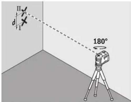
- Merni alat okrenite za 180°, a da ne pomerate visinu. Pustite da se niveliše i označite sredinu tačke drugog bočnog laserskog zraka na zidu (tačka II). Vodite računa o tome da se tačka II po mogućstvu uspravno nalazi iznad odnosno ispod tačke I.
- Razlika d između dve označene tačke l i ll na zidu predstavlja stvarno odstupanje visine mernog alata duž poprečne ose.
Na mernoj deonici od 2 × 20 m = 40 m, maksimalno dozvoljeno odstupanje iznosi:
40 m × ±0,3 mm/m = ±12 mm. Razlika d između tačaka l i ll sme da iznosi maksimalno 12 mm.
Uputstva za rad
- Okrenite mjerni alat za 180° bez promjene visine. Mjerni alat iznivelirajte i označite sredinu točke druge bočne laserske zrake na zidu (točka II). Pazite da točka II po mogućnosti leži okomito iznad odnosno ispod točke I.
- Razlika d obje označene točke I i II na zidu daje stvarno visinsko odstupanje mjernog alata uzduž poprečne osi. Na mjernoj stazi od 2 × 20 m = 40 m maksimalno dopušteno odstupanje iznosi:
40 m × ±0,3 mm/m = ±12 mm. Stoga razlika d između točaka I i II može iznositi najviše 12 mm.
(10) Kanduri kruviauk
(11) Magnet
(12) rihmajuhik
(13) Statiivi kinnitus 5/8" kanduril
(14) Statiivi kinnitus 1/4" kanduril
Palma Tower 10th Floor
Jalan RA Kartini II-S Kaveling 6
Pondok Pinang, Kebayoran Lama
Đơn nguyên 8BC, GT Tower, Tâng 08,
Đường 169, Tiệp Khắc Blvd, Sangkat Veal Vong, Khan 7 Makara, Phnom Penh
VAT TIN: 100 169 511
Tel.: +855 23 900 685
Tel.: +855 23 900 660
www.bosch.com.kh
Sự thải bổ
Robert Bosch Morocco SARL


- GPL 5 Professional
- BOSCH
- Product Description and Specifications
- Intended Use
- Product features
- Fitting
- Inserting/Changing the batteries
- Operation
- Start-up
- Switching On/Off
- Setting the automatic switch-off
- Automatic Levelling
- Accuracy Check of the Measuring Tool
- Influences on Accuracy
- Checking the horizontal levelling accuracy of the longitudinal axis
- | English
- Checking the Horizontal Levelling Accuracy of the Transverse Axis
- Practical Advice
- Working with the measuring plate (accessory)
- Working with the Tripod (Accessory)
- Attaching using the holder
- Laser Viewing Glasses (Accessory)
- Maintenance and Servicing
- Maintenance and Cleaning
- After-Sales Service and Application Service
- Great Britain
- Ireland
- Australia, New Zealand and Pacific Islands
- Republic of South Africa
- Customer service
- Gauteng - BSC Service Centre
- KZN - BSC Service Centre
- Western Cape - BSC Service Centre
- Bosch Headquarters
- Disposal
- | Français
- Only for EU countries:
- Français
- Bortskaffelse
- Avfallshantering
- Бракуване
- Kontrola horizontalne tačnosti u nivelisanju poprečne ose
- Uputstva za rad
- Sự thải bổ
Brand : BOSCH
Model : GPL 5 Professional
Category : Rangefinder