LSDT1202 - Screwdriver RYOBI - Free user manual and instructions
Find the device manual for free LSDT1202 RYOBI in PDF.

User questions about LSDT1202 RYOBI
0 question about this device. Answer the ones you know or ask your own.
Ask a new question about this device
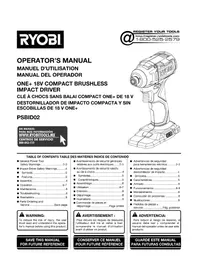
Download the instructions for your Screwdriver in PDF format for free! Find your manual LSDT1202 - RYOBI and take your electronic device back in hand. On this page are published all the documents necessary for the use of your device. LSDT1202 by RYOBI.
USER MANUAL LSDT1202 RYOBI
natural_image
Line drawing of a Ryobi electric drill (no text or symbols on the device body)CE

text_image
1 5 16 RYOBI. 4 2 3 Fig. 1 F
text_image
g. 2 6 7 6
text_image
4 8 C 9 2 Fig. 3
text_image
1 10 11 12 RYC Fig. 4
text_image
13 3 Fig. 5
text_image
1 10 13 1 11 12 g. 6
natural_image
Diagram of a mechanical component with a circular cross-section and diagonal line, labeled Fig. 7 (no text or symbols on the diagram itself)
text_image
14 5 20 15 RYOB Fig. 8
text_image
RYOBI Fig. 9
natural_image
Hand using a RIY OBI tool to lift a wall-mounted component, labeled Fig. 10 (no text on diagram)Important! It is essential that you read the instructions in this manual before operating this machine.
- Keyless chuck
- Switch trigger
- Bit storage
- Rotation selector (forward/reverse)
- Torque adjustment ring
- Depress latches
- Battery pack
- Reverse
- Forward
- Unlock (release)
- Chuck jaws
- Lock (tighten)
- Drill bit
- To decrease torque
- To increase torque
- Two-speed gear switch
- High speed
- Low speed
SPECIAL SAFETY RULES
■ Wear ear protectors. Exposure to noise can cause hearing loss.
■ Hold tool by insulated gripping surfaces when performing an operation where the cutting tool may contact hidden wiring or its cord. Cutting accessory contacting a "live" wire may make exposed metal parts of the power tool "live" and could give the operator an electric shock.
SPECIFICATIONS
Voltage 12 V
Chuck 0.8-10 mm
Switch Variable speed
No-load speed (drill mode)
Low speed 0 - 400 min-1
High speed 0 - 1380 min-1
Maximum torque 25 Nm
Weight (not including battery pack) 1.01 kg
| Model | Battery pack (not included) | Compatible charger (not included) |
| LSDT1202 | BPL1220BPN1213 | C120D |
| BPN1213 | C120N |
OPERATION
WARNING
Do not allow familiarity with products to make you careless. Remember that a careless fraction of a second is sufficient to inflict serious injury.
WARNING
Always wear eye protection marked to comply with ANSI Z87.1. Failure to do so could result in objects being thrown into your eyes, resulting in possible serious injury.
WARNING
Do not use any attachments or accessories not recommended by the manufacturer of this product. The use of attachments or accessories not recommended can result in serious personal injury.
APPLICATIONS
You may use this product for the purposes listed below:
- Drilling in all types of wood products (lumber, plywood, paneling, composition board, and hard board)
- Drilling in ceramics, plastics, fiberglass, and laminates
- Drilling in metals
For complete charging instructions, refer to the Operator's Manual for the battery packs and chargers listed in the specifications section.
BATTERY PROTECTION FEATURES
Ryobi lithium-ion batteries are designed with features that protect the lithium-ion cells and maximize battery life. Under some operating conditions, these built-in features may cause the battery and the tool it is powering to act differently from nickel-cadmium batteries.
During some applications, the battery electronics may signal the battery to shut down, and cause the tool to stop running. To reset the battery and tool, release the trigger and resume normal operation.
English
NOTE: To prevent further shutdown of the battery, avoid forcing the tool.
If releasing the trigger does not reset the battery and tool, the battery pack is depleted. If depleted, the battery pack will begin charging when placed on the lithium-ion charger.
TO INSTALL BATTERY PACK
See Figure 2.
■ Place the rotation selector in the center position.
■ Insert the battery pack into the product as shown.
■ Make sure the latches on each side of the battery pack snap in place and that battery pack is secured in the product before beginning operation.
TO REMOVE BATTERY PACK
WARNING
Always remove battery pack from your tool when you are assembling parts, making adjustments, cleaning, or when not in use. Removing battery pack will prevent accidental starting that could cause serious personal injury.
■ Lock the switch trigger by placing the direction of rotation selector in the center position.
■ Depress the latches on each side of the battery pack.
■ Remove the battery pack from the tool.
WARNING
Battery tools are always in operating condition. Therefore, the switch should always be locked when not in use or carrying at your side.
SWITCH TRIGGER
See Figure 3.
To turn the drill on, depress the switch trigger. To turn it off, release the switch trigger.
NOTE: When selector is in center position, switch trigger is locked.
VARIABLE SPEED
See Figure 3.
The switch trigger delivers higher speed with increased trigger pressure and lower speed with decreased trigger pressure.
NOTE: You might hear a whistling or ringing noise from the switch during use. Do not be concerned; this is a
normal part of the switch function.
ROTATION SELECTOR
See Figure 3.
The bit rotation is reversible and is controlled by a selector located above the switch trigger. With the drill held in normal operating position, the direction of rotation selector should be positioned to the left of the switch trigger for forward drilling. The drilling direction is reversed when the selector is to the right of the switch trigger.
Setting the rotation selector in the off (center lock) position helps reduce the possibility of accidental starting when not in use.
CAUTION
To prevent gear damage, always allow the chuck to come to a complete stop before changing the direction of rotation.
To stop the drill, release the switch trigger and allow the chuck to come to a complete stop.
NOTE: The drill will not run unless the rotation selector is pushed fully to the left or right.
Avoid running the drill at low speeds for extended periods of time. Running at low speeds under constant usage may cause the drill to become overheated. If this occurs, cool the drill by running it without a load and at full speed.
KEYLESS CHUCK
See Figure 4.
The drill has a keyless chuck to tighten or release drill bits in the chuck jaws. The arrows on the chuck indicate which direction to rotate the chuck body in order to lock (tighten) or unlock (release) the drill bit.
WARNING
Do not hold the chuck with one hand and use the power of the drill to tighten the chuck jaws on the drill bit. The chuck body could slip in your hand, or your hand could slip and come in contact with the rotating drill bit. This could cause an accident resulting in serious personal injury.
BIT STORAGE
See Figure 5.
When not in use, bits provided with the drill can be placed in the storage area located on the base of the drill.
English
INSTALLING BITS
See Figure 6 - 7.
■ Lock the switch trigger by placing the direction of rotation selector in the center position.
■ Open or close the chuck jaws to a point where the opening is slightly larger than the bit size you intend to use. Also, raise the front of the drill slightly to keep the bit from falling out of the chuck jaws.
■ Insert the drill bit.
WARNING
Make sure to insert the drill bit straight into the chuck jaws. Do not insert the drill bit into the chuck jaws at an angle then tighten. This could cause the drill bit to be thrown from the drill, resulting in possible serious personal injury or damage to the chuck.
■ Tighten the chuck jaws on the drill bit.
NOTE: Rotate the chuck body in the direction of the arrow marked LOCK to close the chuck jaws. Do not use a wrench to tighten or loosen the chuck jaws.
REMOVING BITS
See Figure 6.
■ Lock the switch trigger by placing the direction of rotation selector in the center position.
■ Open the chuck jaws.
NOTE: Rotate the chuck body in the direction of the arrow marked UNLOCK to open the chuck jaws. Do not use a wrench to tighten or loosen the chuck jaws.
■ Remove the drill bit.
TWO-SPEED GEAR SWITCH (HIGH-LOW)
See Figure 9.
A slide switch is located on top of the drill to select either low (1) or high (2) speed. When using drill in the low (1) speed range, speed will decrease and unit will have more power and torque. When using drill in the high (2) speed range, speed will increase and unit will have less power and torque. Use low (1) speed for high power and torque applications and high (2) speed for fast drilling or driving applications.
ADJUSTABLE TORQUE CLUTCH
See Figure 8.
When using the drill-driver for various driving applications, it becomes necessary to increase or decrease the torque in order to help prevent the possibility of damaging screw
heads, threads, workpiece, and so on. In general, torque intensity should correspond to the screw diameter. If the torque is too high or the screws too small, the screws may be damaged or broken.
The torque is adjusted by rotating the torque adjustment ring. The torque is greater when the torque adjustment ring is set on a higher setting. The torque is less when the torque adjustment ring is set on a lower setting.
The proper setting depends on the type of material and the size of screw you are using.
ADJUSTING TORQUE
■ Identify the 24 torque indicator settings located on the front of the drill.
■ Rotate adjusting ring to the desired setting.
| 1 - 4 For driving small screws |
| 5 - 8 For driving screws into soft material |
| 9 - 12 For driving screws into soft and hard materials |
| 13 - 16 For driving screws in hard wood |
| 17 - 20 For driving large screws |
| 21 - For drilling |
DRILLING
■ Check the direction of rotation selector for the correct setting (forward or reverse).
- Secure the material to be drilled in a vise or with clamps to keep it from turning as the drill bit rotates.
■ Hold the drill firmly and place the bit at the point to be drilled.
■ Depress the switch trigger to start the drill.
■ Move the drill bit into the workpiece, applying only enough pressure to keep the bit cutting. Do not force the drill or apply side pressure to elongate a hole. Let the tool do the work.
WARNING
Be prepared for binding at bit breakthrough. When these situations occur, drill has a tendency to grab and kick opposite to the direction of rotation and could cause loss of control when breaking through material. If not prepared, this loss of control can result in possible serious injury.
■ When drilling hard, smooth surfaces, use a center
English
punch to mark the desired hole location. This will prevent the drill bit from slipping off-center as the hole is started.
■ When drilling metals, use a light oil on the drill bit to keep it from overheating. The oil will prolong the life of the bit and increase the drilling action.
■ If the bit jams in the workpiece or if the drill stalls, stop the tool immediately. Remove the bit from the workpiece and determine the reason for jamming.
NOTE: This drill has an electric brake. When the switch trigger is released, the chuck stops turning. When the brake is functioning properly, sparks will be visible through the vent slots on the housing. This is normal and is the action of the brake.
WOOD DRILLING
For maximum performance, use high speed steel bits for wood drilling.
■ Begin drilling at a very low speed to prevent the bit from slipping off the starting point. Increase the speed as the drill bit bites into the material.
■ When drilling through holes, place a block of wood behind the workpiece to prevent ragged or splintered edges on the back side of the hole.
METAL DRILLING
For maximum performance, use high speed steel bits for metal or steel drilling.
■ Begin drilling at a very low speed to prevent the bit from slipping off the starting point.
■ Maintain a speed and pressure which allows cutting without overheating the bit. Applying too much pressure will:
• overheat the drill
- wear the bearings
- bend or burn bits
• produce off-center or irregular-shaped holes
■ When drilling large holes in metal, start with a small bit, then finish with a larger bit. Also, lubricate the bit with oil to improve drilling action and increase bit life.
MAINTENANCE
WARNING
When servicing, use only identical replacement parts. Use of any other parts may create a hazard or cause product damage.
Avoid using solvents when cleaning plastic parts. Most plastics are susceptible to damage from various
types of commercial solvents and may be damaged by their use. Use clean cloths to remove dirt, dust, oil, grease, etc.
WARNING
Do not at any time let brake fluids, gasoline, petroleum-based products, penetrating oils, etc., come in contact with plastic parts. They contain chemicals that can damage, weaken or destroy plastic.
Do not abuse power tools. Abusive practices can damage tool as well as workpiece.
WARNING
Do not attempt to modify this tool or create accessories not recommended for use with this tool. Any such alteration or modification is misuse and could result in a hazardous condition leading to possible serious personal injury.
ENVIRONMENTAL PROTECTION

Recycle raw materials instead of disposing of as waste. The machine, accessories and packaging should be sorted for environmental-friendly recycling.
SYMBOL

Safety Alert
V Volts
Hz

Hertz
Direct current

Alternating Current
W
Watts
no
No-load speed
min-1
Revolutions or reciprocations per minute

Recycle unwanted

CE Conformity

Double insulation
English

Wear ear protection

Wear eye protection

Please read the instructions carefully before starting the machine.

Waste electrical products should not be disposed of with household waste. Please recycle where facilities exist. Check with your Local Authority or retailer for recycling advice.
Français
DESCRIPTION
LOGEMENT POUR FORETS
Voir fi gure 5.
SNELHEIDSSCHAKELAAR (HOOG-LAAG)
Zie afbeelding 9.
Tomgangshastighed (boretilstand)
Lav hastighed 0 - 400 min-1
VÄXELVÄLJARE (HÖG-LÅG)
Se bild 9.
POSEBNA SIGURNOSNA PRAVILA
■ Nosite πtitnike za utri. Izlaganje buci može izazvati gubitak sluha.
■ Alat držite na izoliranim i protukliznim dijelovima ako radite na podlozi koji bi mogla sakriti električne žice. Dodirivanje „žive“ žice priborom za rezanje može izložiti metalne dijelove alata električnoj energiji i može dovesti do strujnog udara na operatera.
SPECIFIKACIJE
Napon 12 V
Stezna glava 0.8-10 mm
Sklopka Promjenjiva
brzina
Brzina bez opterečenja (način rada bušenja)
Mala brzina 0 - 400 min-1
Velika brzina 0 - 1380 min-1
Maksimalni zakretni moment 25 Nm
Težina (bez baterije) 1.01 kg
| Model | Baterija (nije uključeno) | Kompatibilni punjač (nije uključeno) |
| LSDT1202 | BPL1220BPN1213 | C120D |
| BPN1213 | C120N |
RAD
UPOZORENJE
Opuštanje u radu s alatom dovodi vas do nepažljivog rada. Imajte na umu da je sekunda nepažnje dovoljna da se nanese ozbiljna ozljeda.
UPOZORENJE
Uvijek nosite zaštitu za oči označenu da je u skladu s ANSI Z87.1. Nepoštivanje ove upute može dovesti do toga da predmeti budu odbačeni u vaše oči uzrokujući moguće osobne ozljede.
UPOZORENJE
All Ryobi products are guaranteed against manufacturing defects and defective parts for a period of twenty four (24) months from the date stated on the original invoice drawn up by the retailer and given to the end user. Deterioration caused by normal wear and tear, unauthorised or improper use or maintenance, or overload are excluded from this guarantee as are accessories such as battery packs, light bulbs, blades, fittings, bags, etc. In the event of malfunction during the warranty period, please take the NON-DISMANTLED product, along with the proof of purchase, to your retailer or nearest Authorised Ryobi Service Centre. This warranty in no way affects your legal rights concerning defective products.
FR
GARANTIE - CONDITIONS
The vibration emission level given in this information sheet has been measured in accordance with a standardised test given in EN 60745 and may be used to compare one tool with another. It may be used for a preliminary assessment of exposure. The declared vibration emission level represents the main applications of the tool. However if the tool is used for different applications, with different accessories or poorly maintained, the vibration emission may differ. This may significantly increase the exposure level over the total working period.
An estimation of the level of exposure to vibration should also take into account the times when the tool is switched off or when it is running but not actually doing the job. This may significantly reduce the exposure level over the total working period. Identify additional safety measures to protect the operator from the effects of vibration such as: maintain the tool and the accessories, keep the hands warm, organisation of work patterns.
FR
AVERTISSEMENT
DECLARATION OF CONFORMITY
We declare under our sole responsibility that this product is in conformity with the following standards or standardized documents: 2006/42/EC, 2004/108/EC, EN60745, EN61000, EN55014
| Sound pressure level [K=3 dB(A)] | 66.5 dB(A) |
| Sound power level [K=3 dB(A)] | 77.5 dB(A) |
Vibration emission value
| Drilling into metal [K=1.5 m/s2] | ah.D=0.5 m/s2 |
| Screwdrilling without impact [K=1.5 m/s2] | ah=1.2 m/s2 |

DÉCLARATION DE CONFORMITÉ
Address: 24/F, CDW BUILDING, 388 CASTLE PEAK ROAD, TSUEN WAN, HONG KONG.
Web: www.ttigroup.com
Name/Title: Brian Ellis / Vice President - Engineering
Signature:

Technical File at
Name of company: TTI EMEA
Address: MEDINA HOUSE, FIELDHOUSE LANE, MARLOW, BUCKS, SL7 1TB, UNITED KINGDOM.
Web: www.ttigroup.com
Name/Title: Carl A. Jeffries / Head of Ryobi Product Marketing
Signature:

Trademarks:
The use of the trademark Ryobi is pursuant to a license granted by Ryobi Limited.