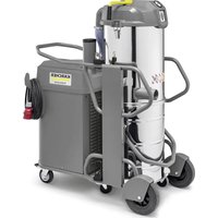
KM 100/120 R G 2SB - Vacuum Cleaner Kärcher - Free user manual and instructions
Find the device manual for free KM 100/120 R G 2SB Kärcher in PDF.

| Product type | Ride-on sweeping vacuum |
| Model | KM 100/120 R G 2SB |
| Brand | Kärcher |
| Dimensions (L × W × H) | 1660 × 1140 × 1355 mm |
| Empty weight | 570 kg |
| Maximum permissible weight | 944 kg |
| Engine | Honda GX 270, 4-stroke single cylinder, 270 cm³, 6.3 kW / 8.4 HP |
| Fuel | Unleaded petrol (min. 91 octane) |
| Fuel tank capacity | 5.3 L |
| Maximum travel speed | 7 km/h |
| Working width (with 1 side broom) | 1000 mm |
| Working width (with 2 side brooms) | 1280 mm |
| Dust hopper volume | 120 L |
| Maximum dumping height | 1520 mm |
| Maximum permissible gradient | 18 % |
| Battery | 12 V maintenance-free |
| Engine oil type | SAE 10W30, API SJ |
| Hydraulic oil type | Shell Tellus S 3 V 68 |
| Sound pressure level (LpA) | 79 dB(A) |
| Guaranteed sound power level (LWA) | 95 dB(A) |
| CO₂ emissions | 762 g/kWh (Stage V) |
| Safety | Seat switch, two-hand control for dumping, parking brake, safety devices on covers |
| Maintenance | Automatic dust filter cleaning, defined maintenance intervals |
Frequently Asked Questions - KM 100/120 R G 2SB Kärcher
User questions about KM 100/120 R G 2SB Kärcher
0 question about this device. Answer the ones you know or ask your own.
Ask a new question about this device
Download the instructions for your Vacuum Cleaner in PDF format for free! Find your manual KM 100/120 R G 2SB - Kärcher and take your electronic device back in hand. On this page are published all the documents necessary for the use of your device. KM 100/120 R G 2SB by Kärcher.
USER MANUAL KM 100/120 R G 2SB Kärcher
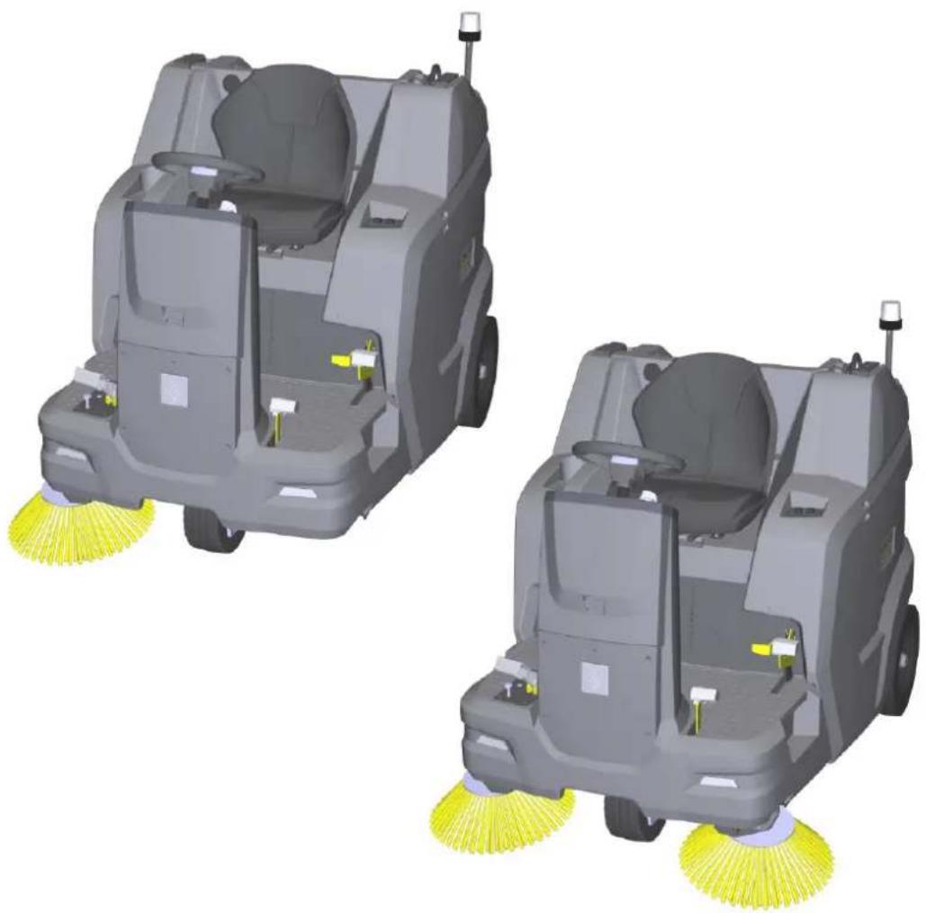
KM 100/120 R G KM 100/120 R G 2SB
natural_image
Two identical 3D renderings of a cleaning or cleaning vehicle with yellow power lines, no text or symbols visible.Deutsch 2
English 20
Français 38
Italiano 56
Español 74
Português 92
Nederlands 110
Türkçe 127
Svenska 145
Suomi 162
Norsk 179
Dansk 196
Eesti 213
Latviešu 230
Lietuviškai 247
Polski 265
Magyar 283
Čeština 301
Slovenčina 318
Slovenščina 336
Română 352
Hrvatski 370
Srpski 388
Ελληνικά 405
Русский 424
Українська 443
Български 462
日本語 481

Register your product
www.kaercher.com/register

EAC
Read Online


59990960

(01/25)
Inhalt
①Fahren
natural_image
3D rendering of a cleaning or cleaning machine with visible door, wheels, and directional arrows indicating motion (no text or symbols)natural_image
3D rendering of a cleaning or cleaning robotic device with labeled parts (no text or symbols visible)natural_image
3D diagram of a vehicle chassis mounted on a platform with a light bulb and directional arrows indicating motion (no text or symbols)natural_image
Interior view of a medical imaging machine with labeled parts (1 and 2), showing internal components and no visible text or symbols beyond labels.①Kraftstoffhahn
natural_image
3D rendering of a robotic cleaning device showing front and side views with no visible text or symbols①Ölmessstab
②Öleinfüllöffnung
①Flügelmutter
②Deckel
③Luftfilter
④ Fixierung
natural_image
Close-up of a brush head with yellow bristles and black central hub, mounted on a car (no text or symbols visible)natural_image
Technical illustration of a cleaning or dust removal device with labeled components (1, 2, 3), showing blade structure and internal structure (no text or symbols beyond labels)natural_image
Close-up of a cleaning machine with a red arrow pointing to the component, showing no visible text or symbols.
H. Jenner
Chairman of the Board of Management

S. Reiser
Director Regulatory Affairs & Certification
71364 Winnenden (Germany)
Tel.: +49 7195 14-0
Fax: +49 7195 14-2212
Winnenden, 2021/06/01
Contents
General notes 20
Intended use 21
Function 21
Safety instructions 21
Device description.... 22
Precommissioning.... 24
Initial startup 25
Operation 26
Transport 27
Storage 28
Care and maintenance 28
Troubleshooting guide 33
Accessories / spare parts.... 35
Technical data 36
Declaration of Conformity 37
General notes
Read the original instructions before using the device for the first time and act in accordance with it. Keep instructions for future reference or for future owners.
Checking the delivery
Please report any defects or shipping damage identified on the vehicle when it is handed over directly to your dealer or department store.
Environmental protection

The packing materials can be recycled. Please dispose of packaging in accordance with the environmental regula-
tions.

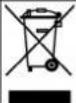
Electrical and electronic devices contain valuable, recyclable materials and often components such as batteries, re-
chargeable batteries or oil, which - if handled or disposed of incorrectly - can pose a potential danger to human health and the environment. However, these components are required for the correct operation of the device. Devices marked by this symbol are not allowed to be disposed of together with the household rubbish.
Notes on the content materials (REACH)
Current information on content materials can be found at: www.kaercher.de/REACH
Disposal of the worn out vehicle
Vehicles that are no longer fit for service contain valuable recyclable materials. We recommend you cooperate with a waste management company with regard to the disposal of your vehicle.
Warranty
The warranty conditions issued by our relevant sales company apply in all countries. We shall remedy possible malfunctions on your appliance within the warranty period free of cost, provided that a material or manufacturing flaw is the cause. In a warranty case, please contact your dealer (with the purchase receipt) or the next authorised customer service site.
(See overleaf for the address)
Further warranty information (if available) can be found in the service area of your local Kärcher website under "Downloads".
Accessories and spare parts
Only use original accessories and original spare parts. They ensure that the appliance will run fault-free and safely.
Information on accessories and spare parts can be found at www.kaercher.com.
Hazard levels
DANGER
- Indication of an imminent threat of danger that will lead to severe injuries or even death.
△WARNING
- Indication of a potentially dangerous situation that may lead to severe injuries or even death.
△CAUTION
- Indication of a potentially dangerous situation that may lead to minor injuries.
ATTENTION
- Indication of a potentially dangerous situation that may lead to damage to property.
Symbols on the machine
△DANGER
Risk of burns from hot surfaces
Allow the vehicle to cool down before working on it.

⚠️DANGER
Risk of fire
Do not sweep up burning or glowing objects such as cigarettes, matches or similar objects.
△DANGER
Risk of accident from tipping
Only use high dumping on level ground.
△WARNING
Risk of injury
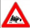
Risk of being squeezed or hurt at the belts, side-brushes, waste container, cover.

△WARNING
Risk of injury
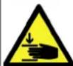
Cut and crush injuries from moving vehicle parts inside. Do not reach into openings in the device.

△DANGER
Risk of accident due to improper handling
Read these operating instructions and the safety instructions before using the device for the first time.

Parking brake

Tyre pressure

Attachment point for jack

Lashing point

Max. load of the storage area 20 kg

Max. load 150 kg
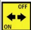
ON position: device can be driven with its own drive OFF position: device can be pushed

Coarse dirt flap pedal

Wet sweeping flap
Releasing/fastening the dust filter
Intended use
Use the sweeper to clean commercial floor areas.
Use the sweeper for the following intended areas of application:
1 Parking spaces
2 Footpaths
3 Production systems
4 Logistics areas
5 Hotels
6 Retail trade
7 Storage areas
Only use the sweeper in accordance with the information in these operating instructions. Any other use is considered as improper use. The manufacturer assumes no liability for any resultant damage. The user is solely responsible for the risk.
The sweeper can only be used with the StVZO attachment kit for operation on public roads.
No modifications must be made to the sweeper.
Only the areas approved by the company or the company's representatives must be driven on and cleaned.
Operation in enclosed spaces is prohibited.
Foreseeable misuse
Never sweep or suction up explosive liquids, gases, non-diluted acids or solvents (e.g. petrol, paint thinner, heating oil) because they form explosive vapours or mixtures in conjunction with the suction air.
Never sweep or suction up acetone, non-diluted acids or solvents, as they will corrode and damage the materials used on the device.
Never sweep or suction up reactive metal dusts (e.g. aluminium, magnesium, zinc). They form explosive gases in conjunction with highly alkaline or acidic cleaning agents.
Do not sweep or suction up burning or smouldering objects.
There is a risk of fire.
Do not sweep up any harmful substances.
Standing in hazard zones is prohibited. Operation in explosive spaces is prohibited.
Carrying passengers is prohibited.
This device must not be used to push/pull or transport objects.
Suitable sweeping surfaces
- Asphalt
- Industrial floor
- Screed
- Concrete
- Paving stones
Function
The sweeper operates using the direct-throw principle.
- The rotating side brushes clean corners and edges of the sweeping surface and convey the waste into the path of the roller brush.
- The rotating roller brush conveys the waste directly into the waste container.
- The dust which is swirled up in the waste container is separated by a dust filter, and the suction fan suctions the filtered clean air.
- The dust filter is cleaned automatically.
Safety instructions
Safety devices
Safety devices protect the user and may not taken out of operation or functionally circumvented.
Adhere to the safety instructions in the chapters!
Bonnet/panel on the right
The bonnet and the right panel have a safety device. When the cover or panel are opened, the running combustion motor is switched off.
The motor can only be started when both are closed.
Emptying the waste container
The roller brush is automatically blocked while the waste container is being emptied.
Waste container two-handed operation
To prevent persons from reaching into the emptying mechanism and the swivel range of the waste container, lifting, lowering and emptying the waste container is only possible with two-handed operation.
Waste container safety brace
It is not permitted to stand under the waste container unless it is fully raised and secured against lowering with the supplied, correctly fitted safety brace.
Seat contact switch
A seat contact switch ensures that the machine can only be started when the driver is sitting in the driver's seat.
Safety instructions for operation
△ WARNING • Only use the device for its proper use. Take into account the local conditions and beware of third parties, in particular children, when working with the device. • Check the device with the operating devices to make sure it is in proper condition and operational safe and reliable. If it is not in perfect condition, you must not use it. • Adhere to the respective safety regulations in hazard zones (e.g. service stations). Never operate the device in explosive spaces. • The device is not intended for use by persons with restricted physical, sensory or mental abilities or those lacking in experience and / or lacking in knowledge.
- Only people who have been instructed on how to use the device, or have proven their ability to operate it, and have been explicitly instructed to use it, must use the device. ATTENTION
- Before starting work, the operator must check whether the safety devices have been attached properly and are fully functional.
- The device operator is responsible for accidents with other people and their property. WARNING • The operator must wear close-fitting clothing and sturdy footwear. Avoid loose-fitting clothing. • Children must be supervised to prevent them from playing with the appliance. • Children and minors must not use the device. ATTENTION • Check the immediate vicinity before setting off (e.g. children). Make sure you have a sufficient view. DANGER • Never leave the device unattended unless the device is secured against unintentional movement. Always apply the parking brake before leaving the device. ATTENTION • Remove the ignition key or KIK (Kärcher Intelligent Key) to prevent unauthorised use of the device. CAUTION • Do not use the device in areas in which there is a possibility of being struck by falling objects. WARNING • Do not look directly into the light source on devices equipped with Blue Spot lighting.
Safety instructions for driving
Note • The list on the risk of overturning is not necessarily comprehensive. DANGER • Danger of tilting if hill or slope is too steep! Observe the maximum permissible values in the technical data when driving up hills and slopes. • Danger of tilting in case of excessive tilting at side! Observe the maximum permissible values in the technical data when driving lateral to the travel direction. • Danger of tilting on unstable subsurfaces! Only use the device on firm subsurfaces.
⚠ WARNING ● Risk of accident due to not adapting speed. Approach corners slowly.
Safety instructions for combustion engines
△ DANGER • Observe the special safety instructions in the operating instructions of the motor manufacturer. • Operation in enclosed spaces is prohibited. • Danger of poisoning: Do not inhale the exhaust gases. • Never close off the exhaust gas openings.
- Never bend down over the exhaust gas opening and take hold of it. - Be aware of the engine after-running time after switching off (3-4 seconds). Keep away from the drive area during this time.
Care and service
⚠ WARNING • Disconnect the battery before working on the electrical system. • Before cleaning, maintenance, replacing parts and resetting to another function, you must switch off the device and remove the ignition key.
△ CAUTION ● Repairs may only be carried out by approved customer service sites or staff qualified in this area who are familiar with all relevant safety instructions.
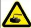
ATTENTION • Adhere to the safety inspection requirements for mobile devices for industrial use in accordance with the locally applicable regulations (e.g. in Germany: VDE 0701). • Short-circuits or other damage. Do not clean the device with a hose or high-pressure water jet. • Always wear suitable gloves when working on the device.
Device description
Device illustration
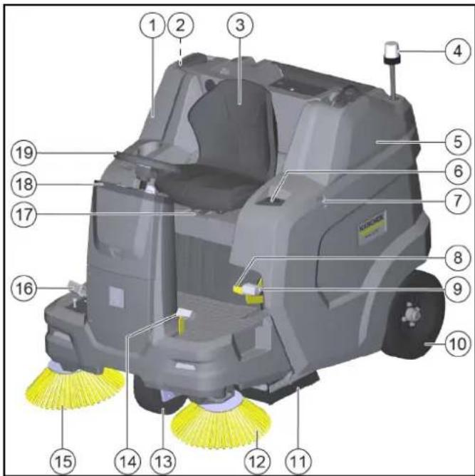
①Right panel (pivoting)
② Waste container safety brace
③Driver's seat (with seat contact switch)
④Flashing beacon
⑤Bonnet (pivoting)
⑥Raising/emptying waste container button
⑦Retaining rail for "Homebase System"
⑧Release the brake
⑨Parking brake
⑩Rear wheel
⑪ Roller brush with sealing strips
⑫Left side brush*
⑬Front wheel
⑭Raising/lowering coarse dirt flap
⑮Right side brush
⑯ Accelerator pedal forward/backward
⑰Seat adjustment lever
18 Control elements**
⑲Steering wheel
* only KM 100/120 R G 2SB
** described in more detail in a later chapter
Optional
The following equipment is not shown if it is already installed at the factory when ordered or can be installed by the service department at a later date.
1 Comfort seat
2 Work light
3 StVZO kit
4 Blue spot
5 Overhead guard
6 Left side brush
7 Water spray system
8 Fleet management module
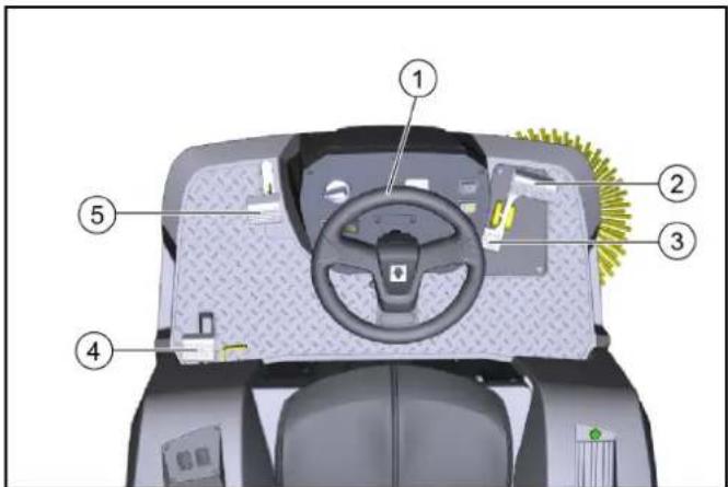
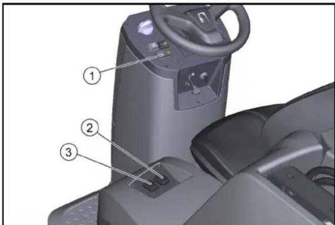
Control elements
① Steering wheel
②Work light switch (option)
③Flashing beacon switch (option)
④Horn
⑤Key-operated switch
⑥"Forward" accelerator pedal
⑦"Reverse" accelerator pedal
⑧Choke lever
⑨High dumping button
⑩ Dust filter cleaning button
⑪ Water spray system switch (option)
⑫Programme selection switch*
⑬ Operating hours counter
* described in more detail in a later chapter
Programme selection switch
Note
The functions are only activated when the key switch is switched on.
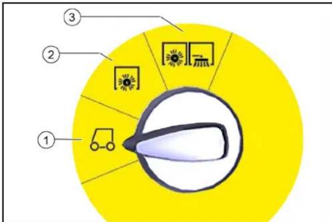
①Driving
- The motor can be started in this position
- The sweeper can be driven to the place of use
– Roller brush and side brushes are raised and switched off
② Sweeping with a roller brush
- Roller brush is lowered and switched on
③ Sweeping with a roller brush, right and left side brushes
- Roller brush, right and left side brushes (optional) are lowered and switched on
Panels
⚠ WARNING
Malfunction due to open panels
Only open the panels when the key switch is on <0> and the key has been removed.
Opening during operation is prohibited.
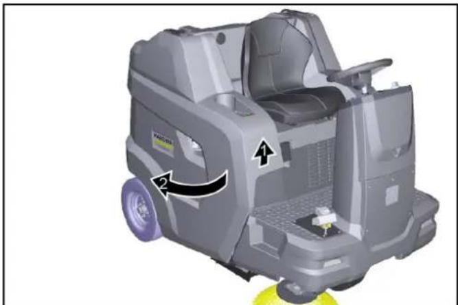
Opening/closing the bonnet
The bonnet must be opened for certain activities:
1 Refuelling
2 Checking/topping up the hydraulic oil level
3 Replace hydraulic oil filter
(only by authorized customer service)
4 Checking/replacing roller brushes
5 Disconnecting the battery
natural_image
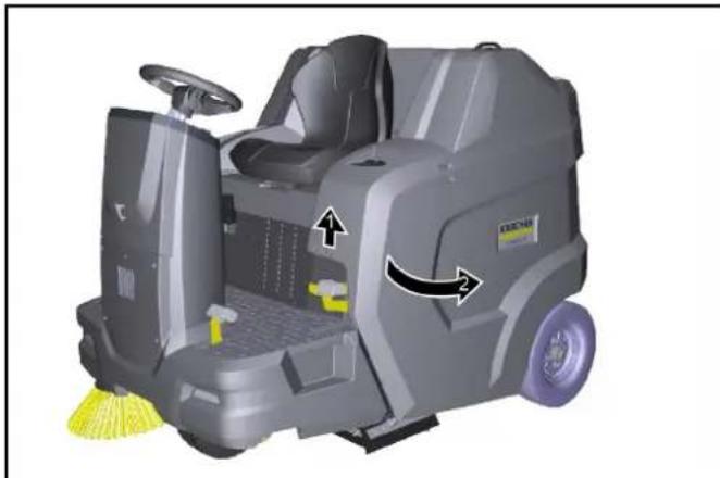
3D rendering of a cleaning or cleaning robot with visible components and directional arrows (no text or symbols)- To open the bonnet, grasp the recessed grip at the front, unlock it upwards, then swivel it to the side.
Opening/closing the right panel
The panel on the right must be opened for certain activities:
1 Opening/closing the freewheel
2 Opening the fuel cock
3 Checking/topping up the engine oil level
4 Motor oil change
5 Checking/replacing spark plug
6 Cleaning/replacing air filters
natural_image
3D rendering of a cleaning or cleaning robot with visible wheels and control panel (no text or symbols)- To open the panel, grasp the recessed grip, unlock it upwards, then swing it to the side.
Storage area
The maximum permissible load on the storage compartments is 20 kg.
1 Ensure that the load is securely fastened.
Batteries / chargers
ATTENTION
Only use the batteries and chargers recommended by the manufacturer
Only replace batteries with batteries of the same type.
Before disposing of the vehicle, remove the battery and dispose of it in accordance with national or local regulations.
Warning symbols
Observe the following warnings when handling the batteries:
 | Observe notes in the instructions of the battery, on the battery and in these operating instructions. |
 | Wear eye protection. |
 | Keep acids and batteries away from children. |
 | Risk of explosion |
 | Fire, sparks, open flames and smoking are prohibited. |
 | Risk of acid burns |
 | First aid |
 | Warning |
 | Disposal |
 | Do not throw batteries in the bin. |
Safety instructions for lead-acid batteries
△DANGER
Danger of fire and explosion!
Do not place tools or similar items on the battery. Risk of short-circuit and explosion.
Smoking and naked flames must be strictly avoided.
Rooms where batteries are charged must have good ventilation as highly explosive gas is emitted during charging.
△DANGER
Risk of acid burns
Use caution with leaking batteries (sulphuric acid may leak).
△DANGER
Risk of injury!
Ensure that wounds never come into contact with lead.
Always clean your hands after working on batteries.
△WARNING
Environmental risk due to improper disposal of batteries
Ensure that defect or used batteries are disposed of safely (contact a waste management company or Kärcher Service).
Procedures in the event of unintentional release of battery acid
When used normally, and when observing the instructions, lead-acid batteries do not pose any risk.
However, keep in mind that lead-acid batteries contain sulphuric acid which can cause serious chemical burns and corrosion.
- If there is spillage or, if the battery is leaking, acid is escaping, lay down a binding agent such as sand. Do not let it reach the sewer system, soil or a body of water.
- Neutralise the acid with lime/baking soda and dispose of it according to local regulations.
- Contact a waste management company to dispose of faulty batteries.
- Rinse out your eyes or rinse off your skin with copious amounts of fresh water if acid splashes into your eyes or onto your skin.
- Then consult a doctor immediately.
- Wash any contaminated clothing with water.
- Change clothes.
Precommissioning
Unloading instructions
△DANGER
Risk of accidents when unloading the device
Use a suitable ramp when unloading the device.
Do not use a forklift to unload / load the device.
Be aware of the weight of the device when unloading / loading.
See also the chapter "Technical data".
natural_image
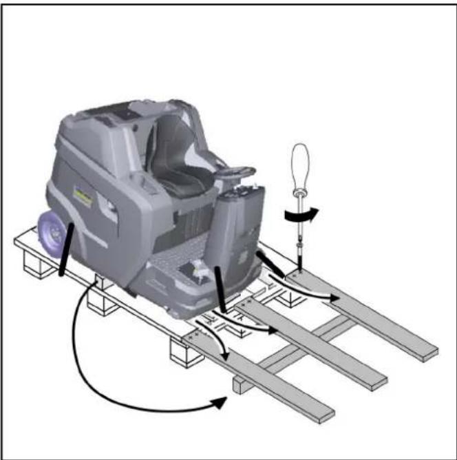
Mechanical assembly diagram showing a motor on a platform with rotating components and a light bulb (no text or symbols)Figure: Ramp
- Connect the battery and charge if necessary.
- Use the enclosed boards to build a ramp according to the sketch.
- Cut the plastic packing strips and remove the film.
- Remove the strap fastening at the attachment points.
- Unscrew the three floor boards shown and the squared timber on the pallet.
- Position the boards on the edge of the pallet; align the boards so that they lie in front on the wheels on the device. Screw the boards tight.
- Place the squared timber under the boards as a support.
- Remove the wooden blocks locking the wheels.
- Release the parking brake.
- Carefully drive the device off the pallet via the ramp (see chapter "Moving the device with its own drive") or push it off the pallet (see chapter "Moving the device without its own drive").
Opening/closing the freewheel lever
△DANGER
Risk of accidents due to absence of braking power
Secure the device to prevent it from rolling away before you actuate the neutral lever.
△CAUTION
Risk of damage to the hydrostatic drive
Push the device slowly and only over a short distance.
Do not tow the device under any circumstances.
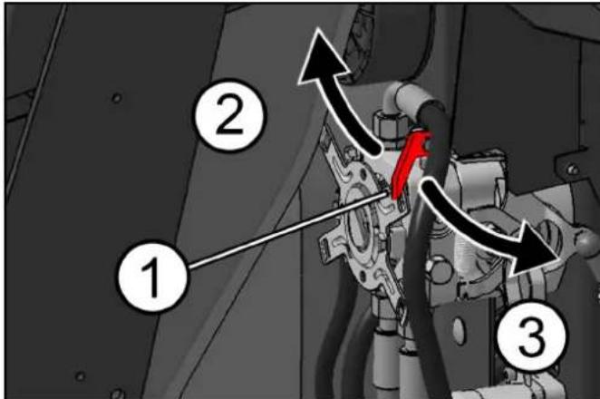
①Neutral lever, red
②Freewheel position closed – The device is ready to c
③Freewheel position open – Device can be pushed
Move device without own drive (device can be moved)
1 Open the neutral lever to move the device.
a Swivel the right panel outwards.
b Pull the neutral lever towards your body (open).
c Release the parking brake.
d Move device.
Moving the device with its own drive (device is ready to drive)
1 After moving the device, close the neutral lever.
a Apply the parking brake.
b Push the neutral lever away from your body (close).
c Close the right panel.
Installing the side brush
Note
The side brush or brushes are attached to the driver's seat with a cable tie when delivered.
- Attach the side brushes to the device before initial startup. See chapter "Changing the side brushes".
Initial startup
Safety check before startup
ATTENTION
Risk of burns from hot surfaces
Stay away from hot motor, exhaust pipe, angle piece and hydraulic drive motor.
Allow the device to cool down before the safety check.
Note
Missing information in the chapter "Care and maintenance | Maintenance work".
-
Check the safety function of the bonnet/panel on the right.
a The combustion motor must not start when the bonnet is open.
b The combustion motor must not start when the panel is open. -
Check the seat contact switch to make sure it is fully functional.
a With the combustion motor running, the device must switch off when the driver gets up from the driver's seat.
- Check the tyre pressure.
- Check the engine oil level.
- Check the filling level of the hydraulic tank.
- Check the roller brush and side brushes for foreign objects and any tangled pieces of tape.
- Check the accelerator pedal for ease of movement and functional reliability (only when the device is at a standstill).
- Empty the waste container.
- Check the filling level of the fuel tank.
Refuelling
△DANGER
Explosion hazard due to overflowing fuel
Take care ensure that no fuel spills onto hot surfaces when refuelling.
△DANGER
Explosion hazard due to smoking and naked flames
Ensure strict prohibition of smoking and open flames during the refuelling procedure.
△WARNING
Health risk from inhaled vapours
Do not refuel in confined spaces.
ATTENTION
Risk of damage due to incorrect fuel
Only fill up with suitable fuel as specified in the technical data.
①Fuel tank
②Fuel cap
③Fuel level indicator
- Switch off the device (switch off the motor).
- Pivot the bonnet outwards.
- Open the tank cap.
- Fill with fuel.
- Wipe of any spilt fuel and close the tank cap.
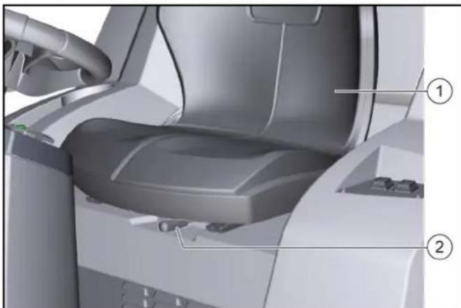
Adjusting the driver's seat
△DANGER
Danger of accident
Only adjust the driver's seat when the device is standing.
natural_image
Interior view of a medical imaging machine with labeled parts (1 and 2), showing internal seating and adjustment knobs (no text or symbols beyond labels)①Driver's seat
②Seat adjustment lever
- Pull the seat adjustment lever to the right and move the driver's seat to the desired position.
- Release the seat adjustment lever.
- Move the driver's seat back and forth to check that it is properly latched in place.
Opening/closing the fuel cock
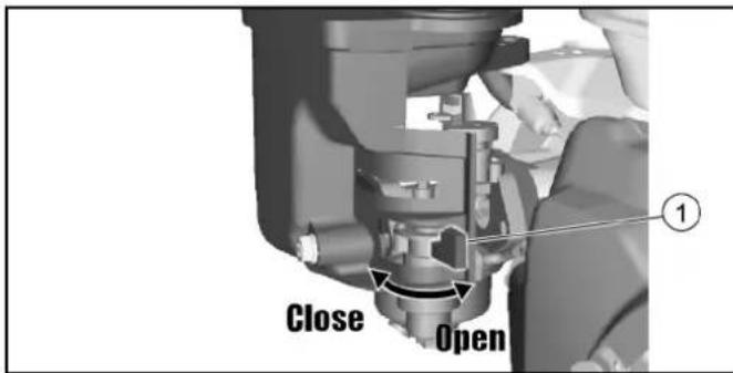
①Fuel cock
1 To open or close the fuel cock, turn it in the corresponding direction up to the stop.
Applying/releasing the parking brake

①Parking brake unlocking
②Parking brake
Apply the parking brake:
1. Press the parking brake (engages).
Release the parking brake:
2. Press the release button, the parking brake is released.
Operation
Starting the device (motor)
Note
To start the motor, the bonnet must be closed and the driver must sit in the driver's seat.
-
Open the fuel cock.
-
Sit in the driver's seat (seat contact switch).
-
Set the programme selection switch to "Drive" position.
-
Insert the key in the key switch and turn to the "I - ON" position, the motor starts.
-
During cold exterior temperatures: Operate the choke lever.
Driving the device
ATTENTION
Risk of injury when reversing
There must be no danger to third parties when reversing. If necessary, have them instructed.
⚠ WARNING
Risk of accident
Do not drive while the waste container is raised.
ATTENTION
Risk of damage to the drive!
Before driving, make sure that the neutral lever is closed. Always press the accelerator pedal carefully and slowly. Do not switch suddenly from reverse to forward drive or vice versa.
① Steering wheel
②Drive forwards
③Drive in reverse
④Parking brake
⑤Coarse dirt flap
- Carefully press the accelerator pedal.
a Continuously regulate the travel speed with the accelerator pedal.
b Avoid jerking the pedal.
c Adapt the travel speed to the respective conditions.
-
Steer the travel direction using the steering wheel.
-
Release the accelerator pedal, the device brakes automatically and stops.
a In an emergency, also apply the parking brake.
Sweeping mode
Information on sweeping operation
△DANGER
Risk of injury from abrupt stopping
Do not get out of the driver's seat while driving or carrying out cleaning work (the seat contact switch brings the device to an abrupt halt).
△WARNING
Risk of injury from stones or chippings
When the coarse dirt flap is open, beware of people, animals and objects in the vicinity (projectile stones or chippings are dangerous).
△CAUTION
Risk of damage due to parcel tape or similar material
Do not sweep parcel tape, pieces of string or similar items (damage to the sweeping mechanics).
Objects or loose obstacles must not be driven over or pushed.
-
Adjust the travel speed to the circumstances for optimum cleaning results.
-
Sweeping is only permitted with the waste container retracted. a If the programme selector is set to "Drive", the container flap is automatically closed.
b If you switch the programme selector switch to "Sweeping", the container flap opens automatically and the waste container is ready to pick up waste.
- Empty the waste container at regular intervals.
a If mainly chippings were swept up (heavy waste), empty the waste container earlier.
-
When cleaning surfaces, set the programme selector to "Sweeping with roller brush".
-
To clean side edges, also use the side brushes by setting the programme selector switch to "Sweeping with roller brush and side brushes".
-
Fixed obstacles up to 6 cm high can be driven over slowly and carefully.
-
Drive over fixed obstacles of more than 6 cm in height with a suitable ramp.
Sweeping with roller brush and side brush
- For cleaning work, select the forwards direction of travel.
- For surface cleaning: Lower the roller brush by setting the programme selector to "Sweeping with the roller brush".
- For wet or damp surfaces: Open the wet sweeping flap.
- For cleaning close to the edge: also lower the right side brushes by setting the programme selector switch to "Sweeping with roller brush and side brushes".
- To pick up larger objects (50 mm): Briefly press the coarse dirt flap pedal.
- Clean the dust filter from time to time. a The dust filter is automatically cleaned at regular intervals. b In dusty environments, also press the filter cleaning switch.
Emptying the waste container
The high dumping system on the unit allows the waste to be directly emptied into a waste container (see chapter "Technical data" for maximum discharge height).
⚠ WARNING
Risk of injury due to falling objects!
When lifting and lowering the waste container, there is a risk of injury from objects falling from the storage surface.
Before lifting the waste container, remove all objects that are not securely fastened from the storage surface.
⚠ WARNING
Risk of injury due to tipping of the machine when emptying the waste container!
Empty the waste container only on firm, level ground.
Maintain a safety distance when emptying on stockpiles and ramps.
⚠ WARNING
Risk of injury when standing in the swivel range of the waste container!
Make sure that no persons or animals are in the swivel range of the waste container during the emptying process.
⚠ WARNING
Risk of injury due to crushing or shearing off of body parts when reaching into the mechanics of the waste container!
Do not reach into the movement area or the components of the emptying mechanism of the waste container.
⚠ WARNING
Risk of injury if the waste container falls!
The raised waste container can fall abruptly and cause serious injuries due to crushing and trapping.
Do not walk underneath the waste container if it is unsecured.
Secure the raised waste container properly with the supplied safety brace before walking underneath the waste container.
①High dumping button
②Switch for raising/lowering the waste container
③Open/close container flap switch
-
Set the programme selector switch to the "Drive" position (the waste container can only be lifted in this position).
-
Roughly position the device.
a After switching off the device, wait at least 1 minute so that the dust can settle before emptying. - Press the high discharge button on the control panel and keep it pressed.
- Press the waste container switch and raise the waste container.
a To empty it into a waste bin, lift the waste container completely and slowly move towards the collection container.
b For free emptying, lift the waste container approximately to the middle until the container flap can be opened (if the emptying height is too low, the operation of the container flap is blocked). - Apply the parking brake.
- Press the container flap switch and empty the waste container.
- Close the container flap.
- Release the parking brake.
- Drive away from the emptying station.
- Lower the waste container completely.
Switching off the device
The dust filter is automatically cleaned when the device is switched off.
1 Park the device on a level surface.
2 Turn the programme selection switch to the "Drive" position.
3 Apply the parking brake.
4 Remove the key from the key switch.
5 Close the fuel cock.
Transport
△DANGER
Risk of accident when loading
Always close the neutral lever when loading the device. Only then are the drive and parking brake ready for operation. The device must always be moved with its own drive on inclines or slopes.
Only load and unload devices on a level surface.
Risk of injury and damage
Note the net weight (transport weight) of the device when transporting it on trailers or vehicles.
Secure the device in accordance with the respectively applicable guidelines to prevent it from slipping or overturning.
natural_image
Interior view of a robotic car with steering wheel and control panel (no visible text or symbols)1 Close the fuel cock.
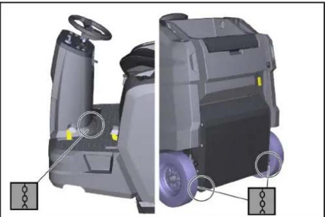
2 Secure the sweeper to the wheels with wedges.
3 Secure the sweeper with lashing straps or ropes.
1 Close the fuel cock.
2 Secure the sweeper to the wheels with wedges.
3 Secure the sweeper with lashing straps or ropes.
Note the markings for fastening areas on the basic frame (chain symbols).
- The left and right rear fastening points are openings (approx. ∅ 30 mm) in the frame between the rear wheel and the waste container.
- At the front is the fastening area between the footrest and the front tower.
4 Disconnect the minus terminal at the battery.
5 Remove key.
Storage
△CAUTION
Risk of injury and damage
Be aware of the weight of the device before storing it.
Additionally, observe the notes in the operating instructions of the motor.
1 Park the sweeper on a level surface in a dry, frost-free environment. Protect against dust with a tarpaulin.
2 Secure the sweeper against rolling away (parking brake).
3 Close the fuel cock.
4 Remove key.
5 Disconnect the negative pole of the battery if the sweeper is not used for more than 4 weeks.
6 Charge the battery approx. every 2 months.
If the sweeper is not used for a long time:
1 Drain the fuel completely from the tank.
2 Change the motor oil.
3 Unscrew the spark plug and pour 5 ml of fresh motor oil into the spark plug bore. Crank the motor several times without the spark plug (do not start). Screw in the spark plug.
Care and maintenance
ATTENTION
Adhere to the safety instructions for care and maintenance at the beginning of these operating instructions.
Cleaning the device
ATTENTION
Short-circuits or other damage. Do not clean the device with a hose or high-pressure water jet.
ATTENTION
Improper cleaning
Risk of damage.
Do not use any abrasive or aggressive detergents.
△DANGER
Health risk from dust
For interior cleaning with compressed air.
Wear a dust mask and safety goggles.
Clean the inside of the device
1 Open panels.
2 Blow out the device with compressed air.
3 Clean the unit using a damp cloth, wetted with a mild washing lye.
4 Closing the panels.
Cleaning the outside of the device
1 Clean the unit using a damp cloth, wetted with a mild washing lye.
Maintenance intervals
Note
To preserve eligibility for warranty claims, all servicing and maintenance work during the warranty period has to be performed by an authorised Customer Service (ICL), in accordance with the inspection check list.
- The operating hour counter indicates the time of the maintenance intervals.
- The intervals for service and maintenance work by the customer/operator are listed in the chapter "Maintenance by the customer". The work must be carried out by qualified staff. A Kärcher specialist dealer can be consulted at any time if needed.
- Further maintenance work must be carried out by the authorized Customer Service according to the inspection checklist. Please inform the Customer Service department in time.
Maintenance by the customer
Note
All servicing and maintenance work must be performed by a qualified specialist. If necessary, you can consult a Kärcher specialist dealer at any time.
Work on the hydraulics may only be carried out by the authorized Customer Service department.
Note
See chapter "Maintenance work" for descriptions.
• Daily
1 See chapter "Safety check before starting".
- Weekly
△WARNING
Risk of injury if the waste container falls!
The raised waste container can fall abruptly and cause serious injuries due to crushing and trapping.
Do not walk underneath the waste container if it is unsecured.
Secure the raised waste container properly with the supplied safety brace before walking underneath the waste container.
1 Check the moving parts to make sure that they move smoothly.
Note
Before all maintenance and repair work with the sweepings container raised, install the safety brace, see chapter Installing/removing the waste container safety brace.
2 Check the sealing strips in the sweeping area for correct adjustment and for wear.
3 Checking sealing strips on container flap of waste container (3x)
4 Check the roller brush and side brush for wear.
5 Check the dust filter and clean the filter box as necessary.
6 Check the air filter.
7 Check the fuel and hydraulic systems for leaks.
8 Check the tension of belts, check for wear and check that they are functional.
- Maintenance every 50 operating hours
1 Clean the air filter (more frequently when used in a dusty environment).
• Maintenance every 100 operating hours
1 Motor oil change (first change after 20 operating hours).
2 Check and clean the spark plug.
3 Clean the air filter.
4 Clean the sediment basin.
- Maintenance every 300 operating hours
1 Change the air filter.
2 Clean the fuel filter.
3 Change the spark plug.
- Maintenance after wear
1 Replace the sealing strips.
2 Replace the roller brush.
3 Replace the side brush.
Maintenance by Customer Service
Note
In order to preserve warranty entitlements, all servicing and maintenance work during the warranty period has to be performed by an authorised Kärcher Customer Service, in accordance with the inspection check list.
- Initial inspection after 20 operating hours
- Maintenance every 100 operating hours
- Maintenance every 300 operating hours
Maintenance work
Checking/topping up the engine oil level
Check the oil level when the device is parked and standing horizontally.
ATTENTION
Danger of burns
Do not touch any hot surfaces such as the exhaust pipe or motor.
①Oil dipstick
②Oil filler opening
③Upper oil level (MAX)
④Lower oil level (MIN)
- Park the device on a level surface.
- Allow the motor to cool.
a Check the motor oil level no earlier than 5 minutes after the motor has been switched off.
- Close the right-hand panel.
- Unscrew the oil dipstick and read the oil level.
a If the oil level is below MIN, top up the motor oil.
For the correct oil type see chapter "Technical data".
b Do not overfill, just fill up to MAX.
- If the oil level is correct, screw in the dipstick.
- Close the panel.
Oil change
Perform the oil change on a warm engine so that the oil drains better.
- Shut down the engine.
- Place the device on a level surface.
- Provide a suitable catch pan for the used oil.
- Open the right panel (pivot).
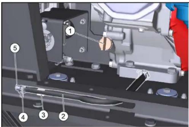
①Dipstick/oil filler opening
②Drain hose
③Drain hose holder
④Hose clamp
⑤Locking piece
- Unscrew the oil dipstick.
- Remove the drain hose from the support.
- Open the hose clip on the drain hose and pull out the locking piece.
-
Allow the oil to drain completely into the catch pan.
-
Insert the locking piece and tighten with a hose clip.
- Fill new engine oil (see "Technical data") up to the lower edge of the filler opening.
11.Screw in and tighten the oil dipstick. - Close the panel.
- Dispose of the old oil in accordance with the environmental regulations.
Check the air filter
- Unscrew the wing nut.
①Wing nut
② Cover
③ Air filter
④Fixing
- Remove the cover.
- Check the air filter for soiling, clean if necessary.
- Slide the cover into the fixing, then put it on. a Pay attention to the correct position in the fixing.
- Screw on the wing nuts and tighten.
Cleaning the air filter
- Unscrew the wing nuts on the cover.
1 Seal
②Cover wing nuts
③Cover
④Air filter wing nuts
⑤Paper filter insert
⑥ Foam filter insert
⑦ Air filter housing
- Remove the cover.
- Unscrew the air filter wing nuts.
- Remove the air filter insert.
- Remove the foam filter insert from the paper filter insert.
- Check both air filter inserts for damage.
- Replace any damaged air filter inserts.
-
Clean any reused air filter inserts.
-
Knock the paper filter insert a few times on a hard surface to clean it or blow it out from the inside with compressed air (maximum 0.2 MPa).
10.Foam filter insert:
a Clean in warm soapy water.
b Rinse with clear water.
c Or clean in a non-inflammable solvent.
d Allow to dry.
e Immerse in clean engine oil.
f Press out the excess oil.
- Wipe off the inner side of the cover and air filter housing with a damp cloth. Take care to ensure that no dirt enters the engine.
- Fit the foam filter insert on the paper filter insert.
- Fit the air filter insert into the air filter housing.
- Ensure that the seal is correctly fitted between the air filter housing and the engine.
- Fit the air filter wing nuts and tighten.
16.Fit the cover. - Fit the cover wing nuts and tighten.
Cleaning the settling cup
- Turn the fuel cock to the "OFF" position.
①Fuel cock
②O-ring
③Settling cup
2. Unscrew the settling cup.
3. Remove the O-ring.
4. Clean the settling cup in a non-inflammable solvent.
5. Thoroughly dry the settling cup.
6. Fit the O-ring into the housing.
7. Screw in and tighten the settling cup.
8. Turn the fuel cock to the "ON" position.
9. Check that the settling cup is tightly seated.
10. Turn the fuel cock to the "OFF" position.
Checking/adjusting the spark plug
- Pull off the spark plug connector.
- Clean the region around the spark plug to prevent dirt from entering the engine when the spark plug is removed.
- Unscrew the spark plug with a 13/16" spark plug wrench.
① Spark plug wrench
②0.7...0.8 mm
③Seal
④Spark plug
- Replace a spark plug that has worn electrodes or a broken insulator.
- Check the electrode gap of the spark plug. Target value 0.7...0.8 mm.
- Check the spark plug seal for damage.
ATTENTION
Risk of damage
A loose spark plug can overheat and damage the engine. An overtightened spark plug can damage the thread in the engine. Observe the following instructions for tightening the spark plug.
7. Carefully screw the spark plug in by hand. Do not cross the thread.
8. Screw the spark plug all the way in using the plug spanner and the tighten as follows.
a Tighten a used spark plug by an additional 1/8...1/4 turn. b Tighten a new spark plug by an additional 1/2 turn.
- Plug on the spark plug connector.
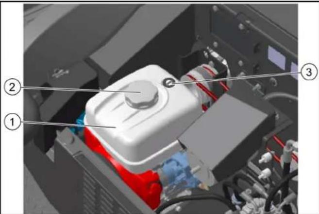
Checking the hydraulic oil level and topping up the hydraulic oil
ATTENTION
Risk of damage to the hydraulic system
Pay attention to the utmost cleanliness when refilling.
Work on the hydraulic system may only be carried out by the authorized Customer Service department.
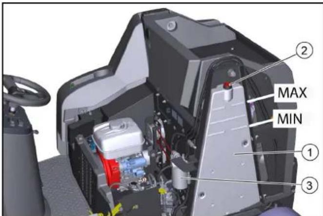
Figure without bonnet
①Hydraulic oil tank
②Breather cap/filler hole
③ Hydraulic oil filter
-
Park the device.
-
Open the bonnet.
-
Check the hydraulic oil level when the motor is cold. a The correct hydraulic oil level must be between the upper "MAX" and lower mark "MIN".
-
Top up the hydraulic oil if necessary.
a Remove the breather cap.
b Top up the hydraulic oil.
For the hydraulic oil type: See chapter "Technical data".
c Attach the breather cap.
- Close the bonnet.
Replacing the rear wheel
⚠ WARNING
Risk of injury
Only park the vehicle on a stable surface.
Check that the ground is stable. Additionally secure the device against rolling away with a wheel chock.
Use a suitable, commonly available jack.
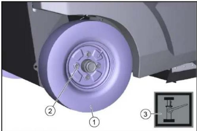
①Rear wheel
②Wheel nut (4x)
③Attachment point icon
- Park the device on a level surface.
a Check that the ground is stable.
b Secure the device against rolling away.
c Open the side panel or bonnet.
- Place the jack at the marked attachment points on the frame.
- Use a suitable tool to release the wheel nuts by approx. 1 turn.
- Lift the device with a jack.
- Unscrew and remove wheel nuts.
- Remove the wheel.
- Have the defective wheel repaired in a specialist workshop or have it replaced.
- Position the wheel, screw in the wheel nuts as far as they will go and tighten slightly.
- Lower the device with the jack.
- Close the side panel or bonnet
- Tighten the wheel nuts to the required torque (56 Nm).
Replacing the front wheel
- Contact the Customer Service department to remove the front wheel.
Replacing the side brush
Thanks to the floating bearing of the side brushes, the sweeping area automatically adjusts itself when the bristles are worn. If it is too worn (bristle length approx. 10 cm), replace the side brushes.
①Side brushes
② Screws
- Park the device.
- Unscrew the 3 screws on the underneath.
- Remove the side brush.
- If necessary, clean the mount.
- Connect the new side brush to the driver and fasten it in place with the screws.
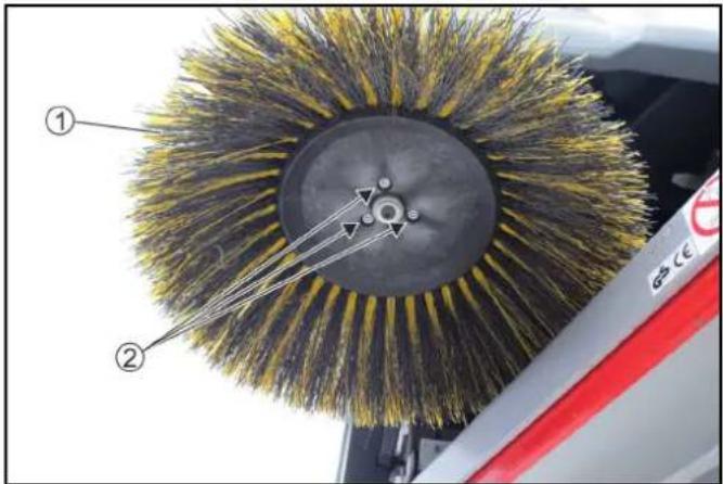
Replacing / inspecting the roller brush
Removing the roller brush
Due to the floating mounting of the roller brush, the sweeping level automatically adjusts itself when the bristles are worn. Replace if it is too worn (cleaning result is not satisfactory).
①Knurled screw, left
② Bearing plate
③Cover plate
④ Knurled screw, right
- Park the device.
- Open the bonnet.
- Unscrew the left-hand knurled screw.
- Remove the bearing plate.
- Unscrew the right-hand knurled screw.
- Remove the cover plate
- Pull out the roller brush.
Installing the roller brush
natural_image
3D mechanical component with a yellow brush head and labeled parts (1, 2, 3), showing internal structure and assembly details (no text or symbols beyond labels)① Roller brush
②Brush roller mount
③ Alignment of the bristles forwards in the direction of travel
1. Check roller brushes for wear and entangled pieces of tape.
2. As necessary: Install the new roller brush.
3. When installing, ensure that the bristles are correctly aligned (roller brush mounts are identical).
4. Install the cover plate and bearing plate in reverse order.
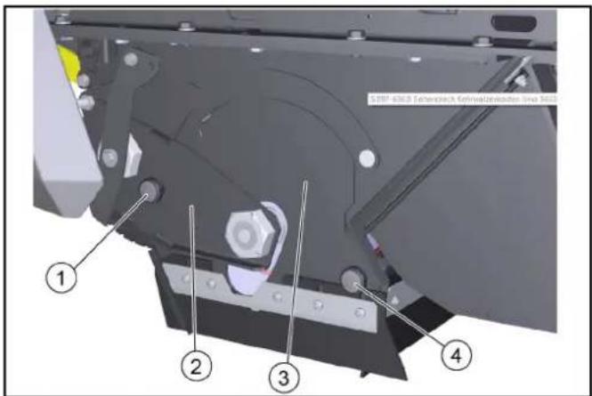
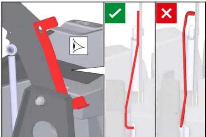
Replacing / setting the sealing strips
Sealing strips Setting values
| Side sealing strips Distance from floor 0 - 1 mm |
| Front sealing strip Trailing distance 10-15 mm |
| Rear sealing strip Trailing distance 5-10 mm |
Note
The trailing distance of the front and rear sealing strip defines how much the sealing lip folds backwards when driving the device forwards.
When set correctly, there must be a gap between the side sealing strips and the floor.
①Fastening
②Side sealing strip
③Front sealing strip
④Rear sealing strip
- Unfasten the fastening of the sealing strips.
- Set the sealing strip by shifting it in the elongated holes. a Refer to the table for the values.
- Once the settings are correct, fasten the sealing strips.
Checking/replacing dust filter
△DANGER
Health risk from dust
Wear a dust mark and safety goggles when working on the filter system.
Observe the safety instructions on the handling of fine dust.
①Bar cover
②Recessed grip
③Dust filter lever
④Dust filter (round filter)
- Park the device.
- Wait at least 1 minute for the dust to settle.
- Pivot the cover upwards on the recessed grip.
- Move the dust filter lever to the right.
- Remove the dust filter upwards.
- As necessary: Clean the dust filter. (vacuum or carefully tap it out) or insert a new dust filter.
Installing/removing the waste container safety brace
Installation:
- Park the machine on a firm, horizontal surface.
- Lower the waste container completely, see chapter Emptying the waste container.
- Switch off the machine, see chapter Switching off the device.
- Open the right-hand panel, see chapter Opening/closing the right panel.
- Remove the safety brace.
a Pull the cotter pins out of the bolts.
b Pull out the bolts and remove the safety brace on the tie bar.
- Position the safety brace between the right-hand tie bar and the right-hand lift arm as shown.
- Install the bolts.
a Insert the bolts into the holes.
b Insert the cotter pins into the holes in the bolts until the cotter pins engage.

ATTENTION
Risk of damage!
Raising or lowering the waste container with the safety brace installed causes damage to the machine and the safety brace! To prevent the waste container from being raised or lowered hydraulically, it is not possible to close the right-hand panel when the safety brace is fitted. This activates the safety circuit.
Do not close the right-hand panel by force!
Removal:
- Removal is performed in the reverse sequence.
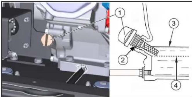
Troubleshooting guide
You can remedy minor faults using the following overview.
Contact the Customer Service department in the case of any faults not listed!
△DANGER
Risk of accidents and injuries due to unintentional movement of the vehicle
Switch off the vehicle before carrying out any care and maintenance work, and remove the ignition key.
△DANGER
Risk of electric shock
Disconnect the battery when working on electrical components. Repair work and work on electrical components must only be performed by your authorised Customer Service.
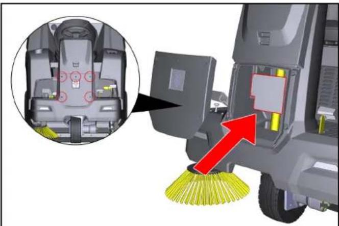
Device fuses
If a function fails, you can check the device fuses before contacting Customer Service.
⚠ WARNING
Risk of damage through incorrect handling
The controller or device components can be damaged by incorrectly inserted device fuses!
Replace device fuses only with fuses of the same type (blade-type fuse) and value (A)
The device fuses are located on the vehicle's electronic controller.
The controller is located under the front cover of the steering column:
natural_image
Diagram of a cleaning or cleaning machine with a close-up inset showing internal components and a red arrow indicating the process (no text or symbols present)- Switch off the device and secure it against rolling away.
- Disconnect the minus terminal at the battery.
- Completely unscrew 5 screws from the front cover.
- Remove the cover.
- Identify faulty device fuses using the table.
- Replace any faulty device fuses.
- Reattach the cover.
- Reconnect the minus terminal of the battery.
Device fuses (overview)
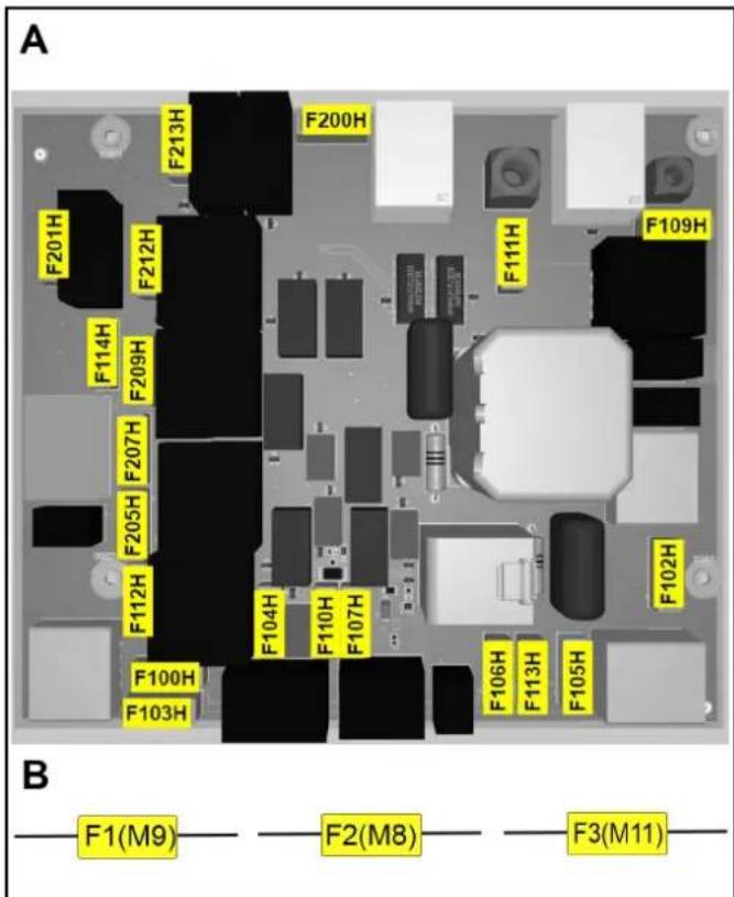
A: Fuses on the electronic controller
| Device fuse Value (A) Designation | ||
| F100H 7.5 Key-operated switch | ||
| F102H 7.5 Work light | ||
| F103H 7.5 Water pump | ||
| F104H 3 LED | ||
| F105H 7.5 Work light | ||
| F106H 3 Blue spot | ||
| F107H 1 Counter | ||
| F109H 5 Filter motor | ||
| F110H 7.5 Signal horn | ||
| F111H 10 Lifting motors | ||
| F112H 5 Start the motor | ||
| F113H 1 Flashing beacon | ||
| F114H 1 Position sensor, | emptying | |
| F200H 30 Main fuse | ||
| F201H 3 K1 Main valve | ||
| F205H 3 K4 Sweeper units | ||
| F207H 3 K6 Open flap | ||
| F209H 3 K3 Close flap | ||
| F212H 3 K5 Lift | ||
| F213H 3 K2 Lower | ||
B: Fuses in the wiring harness (fuse holder)
| Device fuse Value (A) Designation | |
| F1 (M9) 7.5 Lifting motor | |
| F2 (M8) 7.5 Lifting motor | |
| F3 (M11) 7.5 Lifting motor |
| Fault Rectification | |
| Motor will not start | Check/charge the starter battery.Key switch to position “I - ON”.Programme selector switch to "Drive" positionDuring cold exterior temperatures: Operate the choke lever.Sit in the driver's seat (seat contact switch is activated).Fully close the bonnet and right panel.Check motor oil level, top up motor oil if necessary.Fill with fuel.Open the fuel cock.Check spark plug. |
| Motor running irregularly | Check the filling level of the fuel tank.Check the position of the choke lever.Check connections and lines of fuel system.Check/clean/replace spark plug.Clean/replace the air filter. |
| Engine is running, but the device does not drive or just slowly | Release the parking brake.Check the position of the neutral lever.Check/top up the filling level of the hydraulic oil tank.In the event of freezing temperatures and cold hydraulic oil: Allow the device to warm up for at least 3 minutes. |
| Motor does not switch off(programme selector switch and key switch are in the OFF position) | Petrol engine:a Open the bonnet (be careful of the rotating V-belt).b Close the fuel cock. |
| Dust when sweeping / insufficient suction power | Empty the waste container.Check / clean / replace the dust filter.a Check that the dust filter is firmly in place.b In case of light soiling, clean the dust filter.c In case of damage or heavy soiling, replace the dust filter.Check the sealing strips in the sweeping area to check for wear. Readjust or replace if necessary.Check/replace the seals on the filter box.Check/replace sealing strips on waste container. |
| Fault Rectification | |
| Cleaning result not satisfactory | Check the roller brush and side brush for wear, replace them as necessary.Check the sealing strips for wear, replace them as necessary.Check that the coarse dirt flap is fully functional.Close the wet sweeping flap.Check the hydraulic oil tank filling level.Check the hydraulic system for leaks. |
| The roller brush / side brush are not running | Turn the programme selection switch to the desired “Sweeping” programme.Check the filling level of the hydraulic oil tank.Check the hydraulic system for leaks.Check the roller brush / side brush for any tangled pieces of tape.Contact Customer Service. |
| Waste container emptying does not work | The shear protection screw on the waste container (left and right sides) has sheared off, replace the broken screw.Contact Customer Service. |
| The right-hand panel cannot be closed | The waste container is secured with the safety brace. Remove the high-pressure nozzle, see chapterInstalling/removing the waste container safety brace. |
Accessories / spare parts
The following is an overview (excerpts thereof) of wear parts or optionally available accessories.
| Accessories Description Order no. | ||
| Side brush, standard | For indoor and outdoor surfaces | 6.905-986.0 |
| Side brush, soft for | fine dust, on indoor and outdoor surfacesMoisture resistant | 6.906-133.0 |
| Side brush, hard for | removal of stubborn dirt, for outdoor useMoisture resistant | 6.906-065.0 |
| Weed brush Side brush for removing weeds 6.906-065.0 | ||
| Roller brush, standard | For indoor and outdoor surfacesWear and moisture resistant | 6.905-095.0 |
| Roller brush, soft for | fine dust, on indoor and outdoor surfacesMoisture resistant | 6.905-190.0 |
| Roller brush, hard for | removal of stubborn dirt, for outdoor useMoisture resistant | 6.905-191.0 |
| Dust filter (round filter) | 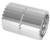 | 6.414-532.0 |
| Sealing strip, side Left and right |  | 5.365-078.0 |
Sealing strip, rear 5:  | ||
Sealing strip, front 5:  | ||
| Side brush attachment kit, left | Has to be installed by Customer Service | 2.852-912.7 |
| Front wheel | As a replacement | 6.435-120.0 |
| Rear wheel | As a replacement | 6.435-291.0 |
| Home Base accessories | Description Order no. | |
| Adapter | For securing to Home Base rail (device) | 5.035-488.0 |
| Double hook | Can only be used in conjunction with adapter | 6.980-077.0 |
| Detergent container | Can only be used in conjunction with adapter | 4.070-006.0 |
| Coarse dirt pliers set | Coarse dirt pliers including attachment to the device | 4.035-524.0 |
Technical data
| KM 100/120 R G KM 100/120 R G 2SB | |||
| Device performance data | |||
| Travel speed (max.) km/h 7 7 | |||
| Working speed (max.) km/h 7 7 | |||
| Climbing ability (max.) % 18 18 | |||
| Working width without side brushes mm 730 730 | |||
| Working width with 1 side brushes mm 1000 1000 | |||
| Working width with 2 side brushes mm 1280 | |||
| Theoretical surface performance | |||
| Surface performance without side brushes | m^2/h | 5110 5110 | |
| Surface performance with 1 side brushes | m^2/h | 7000 7000 | |
| Surface performance with 2 side brushes | m^2/h | 8960 | |
| Battery | |||
| Battery type | Maintenance-free | Maintenance-free | |
| Working voltage of the battery | V | 12 12 | |
| Environmental conditions | |||
| Ambient temperature | °C | -5...+40 | -5...+40 |
| Humidity, non-condensing | % 0...90 | 0...90 | |
| Dimensions and weights | |||
| Length | mm 1660 1660 | ||
| Width | mm 1110 1140 | ||
| Height | mm 1355 1355 | ||
| Net weight (transport weight) | kg | 570 570 | |
| Approved total weight | kg | 944 944 | |
| Width of roller brush | mm 730 730 | ||
| Diameter of roller brush | mm 285 285 | ||
| Diameter of side brush | mm 410 410 | ||
| Waste container | |||
| Waste container volume | l (kg) | 120 120 | |
| Discharge height (max.) | mm 1520 1520 | ||
| Filter and suction system | |||
| Filter area | m^2 | 6 | 6 |
| Internal combustion engine | |||
| Engine type | Honda GX 270 | Honda GX 270 | |
| Type | 1 cylinder 4 stroke | 1 cylinder 4 stroke | |
| Engine capacity | cm^3 | 270 270 | |
| CO2 emission according to the measurement procedure of EU regulation 2016/1628 (level V) | g/kWh | 762 762 | |
| Cooling type | Air-cooled | Air-cooled | |
| Engine performance | kW/PS | 6,3 / 8,4 | 6,3 / 8,4 |
| Spark plug type | BPR6ES (NGK) | BPR6ES (NGK) | |
| Fuel tank capacity | l | 5,3 | 5,3 |
| Engine speed | 1/min | 3600 3600 | |
| Working time with a fully filled fuel tank | h | ca. 3,5 | ca. 3,5 |
| Operating materials | |||
| Fuel type | Benzin bleifrei (min. 91 Oktan) | Benzin bleifrei (min. 91 Oktan) | |
| Engine oil type | API SJ | API SJ | |
| Engine oil volume | l | 1,1 | 1,1 |
| Oil type | SAE 10W30 | SAE 10W30 | |
| Type of hydraulic oil | Shell Tellos S 3 V 68 | Shell Tellos S 3 V 68 | |
| Tyres | |||
| Tyre size, front | ø 300 mm | ø 300 mm | |
| Tyre size, rear | 4.00-8 6PR | 4.00-8 6PR | |
| Tyre pressure | MPa (bar) | 0,6 (6) | 0,6 (6) |
Determined values according to EN 60335-2-72
| Hand-arm vibration value m/s | ^2 | 1,9 1,9 |
| Seat Vibration value m/s | ^2 | 0,4 0,4 |
| Sound level L_pA | dB(A) 79 79 | |
| Uncertainty dB(A) 2,5 2,5 | ||
| Sound power level L_WA + Uncertainty K_WA | dB(A) 95 95 | |
Subject to technical changes without notice.
Declaration of Conformity
EU Declaration of Conformity
We hereby declare that the machine described below complies with the relevant basic safety and health requirements in the EU Directives, both in its basic design and construction as well as in the version placed in circulation by us. This declaration is invalidated by any changes made to the machine that are not approved by us.
Product: Sweeper vacuum
Type: 1.280-xxx.0
Currently applicable EU Directives
2006/42/EC (+2009/127/EC)
2014/30/EU
2000/14/EC
2014/53/EU (TCU)
Harmonised standards used
EN 60335-1
EN 60335-2-72
EN 55012: 2007 + A1: 2009
EN 62233: 2008
TCU
EN 301 511 V12.5.1
EN 300 440 V2.1.1
EN 300 328 V2.2.2
EN 300 330 V2.1.1
Applied conformity evaluation method
2000/14/EG: Annex V
Sound power level dB(A)
Measured: 93
Guaranteed: 95
The signatories act on behalf of and with the authority of the company management.

H. Jenner
Chairman of the Board of Management

S. Reiser
Director Regulatory Affairs & Certification
Documentation supervisor:
S. Reiser
Alfred Kärcher SE & Co. KG
Alfred-Kärcher-Str. 28 - 40
71364 Winnenden (Germany)
Ph.: +49 7195 14-0
Fax: +49 7195 14-2212
Winnenden, 2021/06/01
Declaration of Conformity (UK)
We hereby declare that the machine described below complies with the relevant basic safety and health requirements in the EU Directives, both in its basic design and construction as well as in the version placed in circulation by us. This declaration is invalidated by any changes made to the machine that are not approved by us.
Product: Sweeper vacuum
Type: 1.280-xxx.0
Currently applicable EU Directives
2006/42/EC (+2009/127/EC)
2014/30/EU
2000/14/EC
2014/53/EU (TCU)
Harmonised standards used
EN 60335-1
EN 60335-2-72
EN 55012: 2007 + A1: 2009
EN 62233: 2008
TCU
EN 301 511 V12.5.1
EN 300 440 V2.1.1
EN 300 328 V2.2.2
EN 300 330 V2.1.1
Applied conformity evaluation method
2000/14/EG: Annex V
Sound power level dB(A)
Measured: 93
Guaranteed: 95
The signatories act on behalf of and with the authority of the company management.

H. Jenner
Chairman of the Board of Management

S. Reiser
Director Regulatory Affairs & Certification
Documentation supervisor:
S. Reiser
Alfred Kärcher SE & Co. KG
Alfred-Kärcher-Str. 28 - 40
71364 Winnenden (Germany)
Ph.: +49 7195 14-0
Fax: +49 7195 14-2212
Winnenden, 2021/06/01
Contenu
①Volant
①Conduite
natural_image
3D rendering of a cleaning or cleaning service robot with visible blades and control panel (no text or symbols)natural_image
3D rendering of a cleaning or cleaning robotic device with directional arrows indicating motion (no text or symbols)natural_image
3D diagram of a vehicle chassis mounted on a platform with a light bulb and directional arrows indicating motion (no text or symbols)Figure : Rampe de descente
natural_image
Interior view of a medical imaging machine showing the seating and internal components (no text or symbols visible)natural_image
3D rendering of a robotic cleaning device showing front and side views with labeled components (no text or symbols present)①Jauge d'huile
①Écrou papillon
②Couvercle
③Filtre à air
④ Fixation
①Joint
①Clé à bougie
②0,7...0,8 mm
③Joint
④Bougie
①Balais latéraux
②Vis
natural_image
Technical illustration of a cleaning or dust removal device with labeled components (1, 2, 3), showing blade blades and internal structure (no text or symbols beyond labels)- Monter les boulons.
natural_image
Diagram of a cleaning or cleaning machine with a close-up inset showing internal components and a red arrow indicating clean material (no text or symbols present)2006/42/CE (+2009/127/CE)
2014/30/UE
2000/14/CE
2014/53/EU (TCU)
Chairman of the Board of Management

S. Reiser
Director Regulatory Affairs & Certification
71364 Winnenden (Germany)
① Guida
natural_image
3D rendering of a cleaning or cleaning robot with visible door, wheels, and directional arrows indicating motion (no text or symbols)natural_image
3D rendering of a cleaning or cleaning robotic device with labeled parts (no text or symbols visible)natural_image
3D diagram of a vehicle chassis on a platform with a light bulb and directional arrows indicating motion (no text or symbols)natural_image
Interior view of a medical imaging machine with labeled parts (1 and 2), showing no visible text or symbols beyond labels.natural_image
Side-view diagram of a robotic car with front and side views, showing internal components and control buttons (no text or symbols)Figura senza cofano
①Spazzola laterale
②Viti
natural_image
Technical illustration of a cleaning or dust removal device with labeled components (1, 2, 3), showing blade structure and magnified detail view.①Fissaggio
natural_image
Close-up of a cleaning or cleaning vehicle interior with a broom and a red arrow indicating the process (no text or symbols present)
H. Jenner
Chairman of the Board of Management

S. Reiser
Director Regulatory Affairs & Certification
71364 Winnenden (Germany)
Tel.: +49 7195 14-0
Fax: +49 7195 14-2212
Winnenden, 01/06/2021
①Volante
① Circulación
natural_image
3D rendering of a cleaning or cleaning service robot with visible blades and control panel (no text or symbols)natural_image
3D rendering of a cleaning or cleaning robotic device with labeled parts and directional arrows (no text or symbols)natural_image
3D diagram of a vehicle chassis with a light bulb and rotating components on a platform (no text or symbols)①Palanca de marcha libre, roja
natural_image
Interior view of a medical imaging machine with labeled parts (1 and 2), showing internal components and no visible text or symbols beyond labels.natural_image
3D rendering of a robotic cleaning device showing front and side views with no visible text or symbols①Llave para bujías
②0,7...0,8 mm
③Junta
④Bujía de encendido
Figura sin tapa del motor
①Depósito de aceite hidráulico
①Rueda trasera
②Tuerca de la rueda (4x)
natural_image
Close-up of a cleaning brush head with yellow and black blades, labeled parts ① and ② (no text or symbols on the brush itself)①Cepillos laterales
②Tornillos
natural_image
Technical illustration of a cleaning or dust removal device with labeled components (1, 2, 3), showing blade structure and magnified detail view.① Cubierta
②Retráctil
③Palanca del filtro de polvo
④Filtro de polvo (filtro redondo)
- Montar los pernos.
natural_image
Close-up of a cleaning or cleaning machine with a red arrow pointing to the component, showing no visible text or symbols.2006/42/CE (+2009/127/CE)
2014/30/UE
2000/14/CE
2014/53/EU (TCU)
Chairman of the Board of Management

S. Reiser
Director Regulatory Affairs & Certification
71364 Winnenden (Germany)
Tel.: +49 7195 14-0
Fax: +49 7195 14-2212
Winnenden, 01/06/2021
Índice
①Volante
①Condução
natural_image
3D rendering of a cleaning or cleaning service robot with visible brush and wheel (no text or symbols)natural_image
3D rendering of a gray industrial cleaning or cleaning machine with visible wheels and control panel (no text or symbols)natural_image
3D diagram of a vehicle chassis with conveyor system and light bulb, no text or symbols presentFigura: Rampa de descida
natural_image
Interior view of a medical imaging machine showing the lid and internal components (no text or symbols visible)natural_image
3D rendering of a robotic device showing front and side views with labeled components (no text or symbols present)1 Fechar a torneira de combustível.
2 Imobilizar a varredora com cunhas nas rodas.
3 Fixar a varredora com cintas tensoras ou cabos.
①Junta
②Porca de orelhas da tampa
③Tampa
④Porca de orelhas do filtro de ar
⑤Cartucho do filtro de papel
⑥Cartucho do filtro de espuma
⑦Carcaça do filtro do ar
2. Remover a tampa.
3. Desaparafusar a porca de orelhas do filtro de ar.
4. Remover o cartucho do filtro de ar.
5. Remover o cartucho do filtro de espuma do cartucho do filtro de papel.
①Chave de velas
②0,7...0,8 mm
③Junta
④Vela de ignição
natural_image
Close-up of a cleaning brush head with yellow and black blades, labeled parts ① and ② (no text or symbols on the brush itself)①Vassoura lateral
②Parafusos
natural_image
Technical illustration of a cleaning or dust removal device with labeled components (1, 2, 3), showing blade and mesh structure (no text or symbols beyond labels)natural_image
Close-up of a cleaning or cleaning machine with a broom and yellow brush, showing internal components and a red upward arrow (no text or symbols visible)2006/42/CE (+2009/127/CE)
2014/30/UE
2000/14/CE
2014/53/EU (TCU)
Chairman of the Board of Management

S. Reiser
Director Regulatory Affairs & Certification
①Stuurwiel
Programmakeuzeschakelaar
Instructie
①Rijden
natural_image
3D rendering of a cleaning or cleaning service robot with visible blades and control panel (no text or symbols)natural_image
3D rendering of a cleaning or cleaning robotic device with labeled parts (no text or symbols visible)natural_image
3D diagram of a vehicle chassis mounted on a platform with a light bulb and directional arrows indicating motion (no text or symbols)natural_image
Interior view of a medical imaging machine showing the seating and internal components (no text or symbols visible)①Brandstofkraan
① Vergrendeling parkeerrem
②Parkeerrem
Parkeerrem bedienen:
- Druk de parkeerrem in (vergrendelt).
Parkeerrem loszetten:
Apparaat (motor) starten
Instructie
natural_image
3D rendering of a robotic cleaning device showing front and side views with labeled components (no text or symbols present)①Oliepeilstok / olievulopening
②Aftapslang
③Aftapslanghouder
④ Slangklem
⑤Sluitstuk
①Vleugelmoer
②Deksel
③Luchtfilter
④Bevestiging
①Bougiesleutel
②0,7...0,8 mm
③Afdichting
④Bougie
natural_image
Close-up of a brush head with yellow and black bristles, showing structural details (no text or symbols)①Zijbezem
②Schroeven
natural_image
Technical illustration of a cleaning or dust removal device with labeled components (1, 2, 3), showing blade and mesh structure (no text or symbols beyond labels)①Afdekking
②Greep
③Hendel stoffilter
④Stoffilter (ronde filter)
- Plaats de bouten.
natural_image
Diagram of a cleaning or cleaning machine with a close-up inset showing internal components and a red arrow indicating action (no text or symbols present)
H. Jenner
Chairman of the Board of Management

S. Reiser
Director Regulatory Affairs & Certification
71364 Winnenden (Germany)
Tel.: +49 7195 14-0
Fax: +49 7195 14-2212
Winnenden, 2021/06/01
İçindekiler
Genel uyarılar 127
①Direksiyon
①Sürüş
natural_image
3D rendering of a cleaning or cleaning service robot with visible door, wheels, and directional arrows indicating motion (no text or symbols)natural_image
3D rendering of a cleaning or cleaning robotic device with visible wheels and control panel (no text or symbols)natural_image
3D diagram of a vehicle chassis on a platform with a light bulb and directional arrows indicating motion (no text or symbols)Resim: Iniş rampası
natural_image
Interior view of a medical imaging machine showing internal components and a hand operating the chamber (no text or symbols visible)① Yakıt vanası
natural_image
3D rendering of a robotic cleaning vehicle showing front and side views with labeled components (no text or symbols present)①Kelebek somun
②Kapak
③Hava filtresi
④ Sabitleme
①Buji anahtari
②0,7...0,8 mm
③ Conta
④Buji
①Yan süpürge
②Vidalar
natural_image
Technical illustration of a cleaning or dust removal device with labeled components (1, 2, 3), showing blade blades and internal structure (no text or symbols beyond labels)①Kapak
②Tutamak yuvası
③Toz filtresi kolu
- Civataları takın.
natural_image
Close-up of a cleaning or cleaning machine with a red arrow pointing to the component, showing no visible text or symbols.2006/42/AT (+2009/127/AT)
2014/30/AB
2000/14/AT
2014/53/EU (TCU)

Chairman of the Board of Management

S. Reiser
Director Regulatory Affairs & Certification
Winnenden, 2021/06/01
Innehåll
Allmän information 145
①Köra
natural_image
3D rendering of a cleaning or cleaning service robot with visible door, wheels, and directional arrows indicating motion (no text or symbols)natural_image
3D rendering of a cleaning or cleaning robotic device with directional arrows indicating motion (no text or symbols)natural_image
Mechanical assembly diagram showing a vehicle on a platform with motion arrows indicating movement (no text or symbols present)Bild: Avfartsramp
natural_image
Interior view of a vehicle's seat and dashboard assembly (no text or symbols visible)①Bränslekran
①Ratt
②Kör framåt
③Kör bakåt
④ Parkeringsbroms
⑤ Grovsmutslucka
natural_image
3D model of a robotic cleaning device showing front and side views with no visible text or symbolsnatural_image
Mechanical assembly diagram showing a motor or conveyor system with mounting flanges and a tool interacting with the component (no visible text or symbols)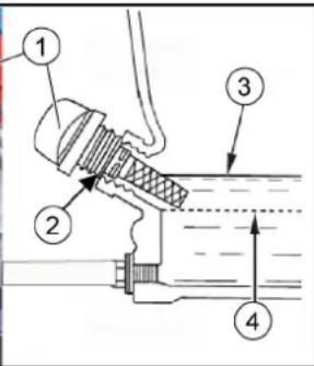
①Oljesticka
②Oljepåfyllningshål
③Övre oljenivå (MAX)
④ Nedre oljenivå (MIN)
①Vingmutter
②Lock
③ Luftfilter
④Fäste
①Packning
② Lockets vingmutter
③Lock
④ Luftfiltrets vingmutter
⑤Pappersfilterinsats
⑥Skumfilterinsats
⑦Luftfilterhus
Figur utan motorhuv
①Bakhjul
②Hjulmutter (4x)
③ Symbol fästpunkt
①Sidborstar
②Skruvar
natural_image
Close-up of a cleaning or cleaning machine with a yellow brush head and labeled parts (1, 2, 3), showing internal structure and assembly details.①Sopvals
②Sopvalsupptagning
①Fäste
② Sidotätningslist
- Montera bultarna.
natural_image
Diagram of a cleaning or cleaning machine with a close-up inset showing internal components and a red arrow indicating the process (no text or symbols present)
H. Jenner
Chairman of the Board of Management

S. Reiser
Director Regulatory Affairs & Certification
D-71364 Winnenden (Germany)
Tfn: +49 7195 14-0
Fax: +49 7195 14-2212
Winnenden, 01.06.2021
Sisältö
① Ajaminen
natural_image
3D rendering of a cleaning or cleaning service robot with visible door, wheels, and directional arrows indicating motion (no text or symbols)natural_image
3D rendering of a cleaning or cleaning robot with visible wheels and control panel (no text or symbols)natural_image
3D diagram of a mechanical assembly with rotating components and a light bulb, no text or symbols presentKuva: Ajoluiska
natural_image
Interior view of a medical imaging machine with labeled parts (1 and 2), showing no visible text or symbols beyond labels.①Ohjauspyörä
②Eteenpäin ajaminen
natural_image
3D rendering of a robotic cleaning device showing front and side views with no visible text or symbols①Tulppa-avain
②0,7...0,8 mm
③Tiiviste
④Sytytystulppa
①Sivuharja
②Ruuvit
natural_image
3D mechanical component with a yellow brush head and labeled parts (1, 2, 3), showing internal structure and assembly details (no text or symbols beyond labels)①Suojus
- Asenna pultit.
natural_image
Diagram of a cleaning or cleaning vehicle with a broom and yellow brush, showing internal components and a red arrow indicating action (no text or symbols present)
Chairman of the Board of Management

S. Reiser
Director Regulatory Affairs & Certification
71364 Winnenden (Germany)
Puh.: +49 7195 14-0
Egnet belegg for feiing
- Asfalt
- Industrigulv
- Støpte gulv
- Betong
- Brostein
Funksjon
①Kjøring
natural_image
3D rendering of a cleaning or cleaning machine with visible components and directional arrows (no text or symbols)natural_image
3D rendering of a cleaning or cleaning robot with directional arrows indicating motion (no text or symbols)natural_image
3D diagram of a mechanical assembly with rotating components and a light bulb, no text or symbols presentBilde: Nedkjøringsrampe
①Drivstofftank
②Tanklokk
③Tankindikator
natural_image
Interior view of a medical imaging machine with labeled parts (1 and 2), showing no visible text or symbols beyond labels.①Førersete
② Setejusteringsspak
① Frigjøre parkeringsbremsen
②Parkeringsbrems
①Ratt
②Kjøre framover
③Kjøre bakover
④Parkeringsbrems
⑤ Grovsmusspjeld
natural_image
3D rendering of a robotic car interior showing front and side views with no visible text or symbols①Oljepeilepinne
①Vingemutter
②Deksel
③ Luftfilter
④Holder
①Pakning
②Vingemutter deksel
③Deksel
④Vingemutter luftfilter
⑤Papirfilterinnsats
⑥ Skumfilterinnsats
⑦ Luftfilterhus
①Drivstoffkran
②O-ring
③Bunnfallskar
Kontrollere tennplug, stille inn
①Tennpluggnøkkel
②0,7-0,8 mm
③Pakning
④Tennplugg
- Dersom tennpluggens elektroder er slitte eller dens isolator er brukket skal den skiftes ut.
- Kontroller elektrodeavstanden til tennpluggen. Nominell verdi 0,7–0,8 mm.
- Kontroller pakningen til tennpluggen for skader.
OBS
Fare for materielle skader
①Bakhjul
②Hjulmutter (4x)
③ Symbol festepunkt
①Sidekost
②Skruer
- Parker maskinen.
- Skru ut tre skruer på undersiden.
- Ta av sidekosten.
- Rengjør festet ved behov.
- Sett den nye sidekosten på medbringeren og fest den med skruer.
Skifte/kontrollere feievalsen
Ta ut feievalsen
natural_image
3D mechanical component with a yellow and gray brush head, showing internal structure and three labeled parts (1, 2, 3), no readable text or symbols beyond labels.①Deksel
②Håndtaksfordypning
③ Spak for støvfilter
④Støvfilter (rundt filter)
natural_image
Diagram of a cleaning or cleaning machine with a close-up inset showing internal components and a red arrow indicating the process (no text or symbols present)2006/42/EF (+2009/127/EF)
2014/30/EU
2000/14/EF
2014/53/EU (TCU)
Anvendte harmoniserte standarder
EN 60335-1
EN 60335-2-72
EN 55012: 2007 + A1: 2009
EN 62233: 2008
TCU
EN 301 511 V12.5.1
EN 300 440 V2.1.1
EN 300 328 V2.2.2
EN 300 330 V2.1.1
2000/14/EF: Vedlegg V
Lydeffektnivå dB(A)
Målt: 93
Garantert: 95

Chairman of the Board of Management

S. Reiser
Director Regulatory Affairs & Certification
71364 Winnenden (Germany)
Tlf.: +49 7195 14-0
Winnenden, 2021/06/01
Indhold
①Rat
①Kørsel
-Motoren kan startes i denne position
natural_image
3D rendering of a cleaning or cleaning service robot with visible components and directional arrows (no text or symbols)natural_image
3D rendering of a cleaning or cleaning robotic device with directional arrows indicating motion (no text or symbols)natural_image
3D diagram of a vehicle chassis on a platform with a light bulb and directional arrows indicating motion (no text or symbols)① Frigearsarm, rød
②Position frigear lukket
natural_image
Interior view of a medical imaging machine with labeled parts (1 and 2), showing internal components without any text or symbols.①Brændstofhane
natural_image
3D rendering of a robotic cleaning device showing front and side views with no visible text or symbols①Oliemålepind
①Vingemøtrik
②Dæksel
③ Luftfilter
④Fiksering
①Pakning
②Vingemøtrik dæksel
③Dæksel
④Vingemøtrik luftfilter
⑤Papirfilterindsats
⑥Skumfilterindsats
⑦Luftfilterhus
①Tændrørsnøgle
②0,7...0,8 mm
③Pakning
④Tændrør
①Baghjul
②Hjulmøtrik (4x)
③Løftepunkt-symbol
①Sidekost
②Skruer
natural_image
Technical illustration of a mechanical sweep or snow impeller assembly with numbered components (1, 2, 3), showing internal blades and mounting features.①Afdækning
② Grebfordybning
③Støvfilterarm
④Støvfilter (rundfilter)
- Monter boltene.
natural_image
Diagram of a cleaning or cleaning machine with a red arrow pointing to the component, showing no visible text or symbols.2006/42/EF (+2009/127/EF)
2014/30/EU
2000/14/EF
2014/53/EU (TCU)

Chairman of the Board of Management

S. Reiser
Director Regulatory Affairs & Certification
71364 Winnenden (Germany)
Tlf.: +49 7195 14-0
Fax: +49 7195 14-2212
Winnenden, 2021/06/01
Sisukord
Üldised juhised.... 213
①Rooliratas
① Sõitmine
natural_image
3D rendering of a cleaning or cleaning robot with visible blades and control panel (no text or symbols)natural_image
3D rendering of a cleaning or cleaning machine with directional arrows indicating motion (no text or symbols visible)natural_image
3D diagram of a vehicle chassis on a track with a light bulb and directional arrows indicating motion (no text or symbols)natural_image
Interior view of a medical imaging machine showing the seating and internal components (no text or symbols visible)①Juhiiste
②Istmeseadistushoob
①Kütusekraan
①Seisupiduri lahtilukusti
②Seisupidur
Seisupiduri vajutamine:
- Vajutage seisupidurit (fikseerub).
Seisupiduri vabastamine:
①Rooliratas
②Edaspidi söitmine
③Tagurdamine
④ Seisupidur
⑤Jämeda mustuse klapp
natural_image
3D rendering of a robotic cleaning vehicle showing front and side views with no visible text or symbols①Õlimõõtevarras
②Õlitäiteava
③ülemine ölitase (MAX)
④ alumine ölitase (MIN)
-
Pange seade tasasel pinnal seisma.
-
Laske mootoril maha jahtuda.
①Kütusekraan
②O-röngas
③Settetops
①Külghari
②Poldid
natural_image
Technical illustration of a street cleaning machine with three labeled components (1, 2, 3), showing blade blades and internal structure (no text or symbols beyond labels)①Kinnitus
①Kate
②Haardesüvend
③Tolmufiltri hoob
④Tolmufilter (ümarfilter)
- Paigaldage poldid.
a Pistke poldid puuravadesse.
natural_image
Diagram of a cleaning or cleaning machine with a close-up inset showing internal components and a red arrow indicating the process (no text or symbols present)2006/42/EÜ (+2009/127/EÜ)
2014/30/EL
2000/14/EÜ
2014/53/EU (TCU)

Chairman of the Board of Management

S. Reiser
Director Regulatory Affairs & Certification
71364 Winnenden (Germany)
Tel: +49 7195 14-0
Winnenden, 2021/06/01
Saturs
①Braukt
natural_image
3D rendering of a cleaning or cleaning service robot with visible door, wheels, and yellow safety clips (no text or symbols)natural_image
3D rendering of a cleaning or cleaning industrial machine with labeled parts (no text or symbols visible)natural_image
3D diagram of a vehicle chassis on a platform with a light bulb and directional arrows indicating motion (no text or symbols)①Degvielas tvertne
②Degvielas uzpildes korkis
③Tvertnes satura indikācija
natural_image
Interior view of a medical imaging machine showing internal components and a hand operating the chamber (no text or symbols visible)①Degvielas krāns
natural_image
3D rendering of a robotic device showing front and side views with no visible text or symbols①Spärnuzgrieznis
②Vāks
③Gaisa filtrs
④Fiksators
natural_image
Close-up of a cleaning brush head with yellow bristles and black center, labeled parts ① and ② (no text or symbols on the brush itself)①Sānu slota
②Skrūves
natural_image
Mechanical cleaning device showing a brush head with yellow filter blades and a close-up of the blade structure (no text or symbols visible)①Pärsegs
②legremdētais rokturis
③Puteklu filtra svira
④ Puteklu filtrs (apałais filtrs)
- Nostipriniet bultskrüves.
natural_image
Close-up of a cleaning robot's floor with a broom and yellow brush, showing internal components and a red arrow indicating cleaning direction (no text or symbols present)Chairman of the Board of Management

S. Reiser
Director Regulatory Affairs & Certification
①Dešinysis gaubiamasis apsaugas (pasukamasis)
①Važiavimas
natural_image
3D rendering of a cleaning or cleaning robot with visible door, wheels, and directional arrows indicating motion (no text or symbols)natural_image
3D rendering of a cleaning or cleaning robotic device with visible wheels and control panel (no text or symbols)natural_image
3D diagram of a vehicle chassis on a platform with a light bulb and directional arrows indicating motion (no text or symbols)natural_image
Interior view of a modern car steering wheel with labeled parts (no text or symbols beyond labels)①Vairuotojo sédyné
② Sédynés reguliavimo svirtis
① Degalu čiaupas
natural_image
3D rendering of a robotic device showing front and side views with no visible text or symbols①Degalų čiaupas
② O" formos žiedas
③Nusodintuvas
Pav. be variklio gaubto
①Galinis ratas
②Rato veržlé (4×)
③Paémimo taško piktograma
natural_image
Close-up of a mechanical cleaning device showing a blade with yellow filter blades and a close-up inset of the blade's edge detail (no text or symbols visible)①Tvirtinimas
① Gaubtas
②Ileistiné rankena
- Jsukite varžtus.
natural_image
Diagram of a cleaning or cleaning machine with a close-up inset showing internal components and a red arrow indicating the process (no text or symbols present)
H. Jenner
Chairman of the Board of Management

S. Reiser
Director Regulatory Affairs & Certification
①Jazda
natural_image
3D rendering of a cleaning or cleaning service robot with visible door, wheels, and directional arrows indicating motion (no text or symbols)natural_image
3D rendering of a cleaning or cleaning industrial machine with visible wheels and control panel (no text or symbols)natural_image
3D diagram of a vehicle chassis mounted on a platform with a light bulb and directional arrows indicating motion (no text or symbols)①Zbiornik paliwa
② Wlew paliwa
natural_image
Interior view of a medical imaging machine with labeled parts (1 and 2), showing internal components and a hand interacting with the lid (no text or symbols beyond labels)①Zawór paliwa
natural_image
3D rendering of a robotic cleaning device showing front and side views with no visible text or symbols①Bagnet pomiarowy
①Tylne koło
natural_image
Close-up of a cleaning brush head with yellow and black blades, labeled parts ① and ② (no text or symbols on the brush itself)①Szczotka boczna
②Śruby
natural_image
Technical illustration of a cleaning or dust removal device with three labeled components (1, 2, 3), showing blade structure and internal structure (no text or symbols beyond labels)natural_image
Diagram of a cleaning or cleaning machine with a close-up inset showing internal components and a red arrow indicating clean material (no text or symbols present)2006/42/WE (+2009/127/WE)
2014/30/UE
2000/14/WE
2014/53/EU (TCU)
Chairman of the Board of Management

S. Reiser
Director Regulatory Affairs & Certification
71364 Winnenden (Germany)
Tel.: +49 7195 14-0
①Jármű mozgása
natural_image
3D rendering of a cleaning or cleaning machine with visible door, wheels, and directional arrows indicating motion (no text or symbols)natural_image
3D rendering of a cleaning or cleaning robot with directional arrows indicating motion (no text or symbols)natural_image
3D diagram of a vehicle chassis mounted on a ladder with a light bulb and directional arrows indicating motion (no text or symbols)natural_image
Interior view of a medical imaging machine showing the seating and internal components (no text or symbols visible)natural_image
3D rendering of a robotic cleaning device showing front and side views with no visible text or symbolsnatural_image
Technical illustration of a cleaning or dust removal device with labeled components (1, 2, 3), showing blade and brush patterns (no text or symbols beyond labels)natural_image
Diagram of a cleaning or cleaning machine with a close-up inset showing internal components and a red arrow indicating action (no text or symbols present)
Chairman of the Board of Management

S. Reiser
Director Regulatory Affairs & Certification
Winnenden, 2021/06/01
Obsah
①Jízda
natural_image
3D rendering of a cleaning or cleaning service robot with visible door, wheels, and directional arrows indicating motion (no text or symbols)natural_image
3D rendering of a cleaning or cleaning service robot with visible wheels and control panel (no text or symbols)natural_image
3D diagram of a mechanical assembly with rotating components and a light bulb, no text or symbols presentobr.: Odjezdová rampa
natural_image
Interior view of a vehicle's steering wheel and dashboard with labeled parts (no text or symbols beyond labels)①Palivový kohout
①Volant
② Pojíždění vpřed
③ Pojíždění zpět
④Parkovací brzda
⑤Klapka na hrubé nečistoty
natural_image
3D rendering of a robotic car interior showing front and side views with no visible text or symbols①Postranní kartáč
②Šrouby
natural_image
Close-up of a cleaning or cleaning machine with a brush head and three labeled parts (1, 2, 3), showing internal structure and assembly details.①Kryt
- Namontujte čepy.
natural_image
Diagram of a cleaning or cleaning vehicle with a broom and yellow brush, showing internal components and a red arrow indicating motion (no text or symbols present)2006/42/ES (+2009/127/ES)
2014/30/EU
2000/14/ES
2014/53/EU (TCU)
Chairman of the Board of Management

S. Reiser
Director Regulatory Affairs & Certification
Winnenden, 2021/06/01
KM 100/120 R G KM 100/120 R G 2SB
dB(A) 95 95
Obsah
①Volant
①Jazda
natural_image
3D rendering of a cleaning or cleaning robotic vehicle with visible door, wheels, and control panel (no text or symbols)natural_image
3D rendering of a cleaning or cleaning robotic device with labeled parts (no text or symbols visible)- Pri otváraní obloženie uchopte za uchopovaciu priehlbinu, odblokujte smerom nahor a potom odklopte na stranu.
Odkladacia plocha
natural_image
3D diagram of a vehicle chassis mounted on a platform with a light bulb and directional arrows indicating motion (no text or symbols)natural_image
Interior view of a modern industrial machine with labeled parts (1 and 2), showing internal seating and control panel (no text or symbols beyond labels)① Sedadlo vodiča
② Páčka na prestavovanie sedadla
①Palivový ventil
①Odblokovanie parkovacej brzdy
②Parkovacia brzda
Aktivovanie parkovacej brzdy:
- Zatlačte parkovaciu brzdu (zapadne).
Uvol'nenie parkovacej brzdy: - Stlačte odblokovanie, parkovacia brzda sa uvoľní.
Prevádzka
①Volant
②Presuňte sa dopredu
③Presuňte sa dozadu
④Parkovacia brzda
⑤Klapka pre hrubé nečistoty
natural_image
3D rendering of a robotic device showing front and side views with labeled components (no text or symbols present)1 Zatvorte palivový ventil.
2 Zametací stroj na kolesách zaistite klinmi.
3 Zametací stroj zaistite upínacími popruhmi alebo lanami. Dbajte na značky pre oblasti upevnenia na základnom ráme (symboly reťaze).
①Kridlová matica
②Veko
③Vzduchový filter
④Fixácia
①Zadné koleso
②Kolesové matice (4x)
③ Symbol upevňovacieho bodu
- Prístroj odstavte na rovnej ploche.
natural_image
Close-up of a cleaning brush head with yellow bristles and black circular base, labeled parts ① and ② (no text or symbols on the brush itself)natural_image
3D rendering of a street cleaning machine with a yellow brush and mesh filter, showing three views (①, ②, ③) — no text or symbols present.①Zametací valec
②Upevnenie zametacieho valca
③Vyrovnanie štetín dopredu v smere jazdy
①Upevnenie
②Bočná tesniaca lišta
③Predná tesniaca lišta
④Zadná tesniaca lišta
①Kryt
②Priehlbina rukoväte
- Namontujte čapy.
a Čapy zasuňte do otvorov.
natural_image
Diagram of a cleaning or cleaning vehicle with a broom and brush, showing internal components and a red arrow indicating motion (no text or symbols present)- Vypnite zariadenie a zaistite ho proti samovolnému pohybu.
- Odpojte minusový pól batérie
- Odskrutkujte 5 skrutiek predného krytu.
- Odoberte kryt.
- Pomocou tabuľky identifikujte chybnú poistku zariadenia.
- Vymeňte chybnú poistku zariadenia.
- Kryt znovu? namontujte.
- Znovu pripojte mínusový pól batérie.
Poistky zariadenia (prehl'ad)

2006/42/ES (+2009/127/ES)
2014/30/EÚ
2000/14/ES
2014/53/EU (TCU)

H. Jenner
Chairman of the Board of Management

S. Reiser
Director Regulatory Affairs & Certification
71364 Winnenden (Germany)
Tel.: +49 7195 14-0
Fax: +49 7195 14-2212
Winnenden, 01.06.2021
Kazalo
Splošna navodila 336
Namenska uporaba 337
Delovanje.... 337
Varnostna navodila 337
Opis naprave 338
Pred zagonom 340
Zagon.... 341
Obratovanje 342
Transport 343
①Krmilo
①Vožnja
natural_image
3D rendering of a cleaning or cleaning robot with visible door, wheels, and directional arrows indicating motion (no text or symbols)natural_image
3D rendering of a cleaning or cleaning service robot with visible wheels and control panel (no text or symbols)natural_image
3D diagram of a mechanical assembly with rotating components and a light bulb, no visible text or symbols①Rezervoar za gorivo
②Zapiralo rezervoarja za gorivo
③Prikaz zaloge goriva
- Izklopite napravo (izklopite motor).
- Pokrov motorja zasukajte navzven.
- Odprite zapiralo rezervoarja za gorivo.
- Natočite gorivo.
- Obrišite prelito gorivo in zaprite zapiralo rezervoarja za gorivo.
natural_image
Interior view of a vehicle's steering wheel and dashboard with labeled parts (no text or symbols beyond labels)①Pipa za gorivo
1 Če želite odpreti ali zapreti pipo za gorivo, jo obrnite do konca v ustrezno smer.
①Krmilo
②Vozite naprej
③Vozite nazaj
④Parkirna zavora
①Tipka za visoko praznjenje
②Stikalo za dvig/spust zbiralnika smeti
③Stikalo za odpiranje/zapiranje lopute zbiralnika
1. Stikalo za izbiro programa nastavite v položaj za vožnjo (zbiralnik smeti je mogoče dvigniti samo v tem položaju).
2. Napravo približno postavite.
natural_image
3D rendering of a robotic car interior showing front and side views with no visible text or symbolsnatural_image
Mechanical assembly diagram showing a motor and gear assembly (no visible text or labels)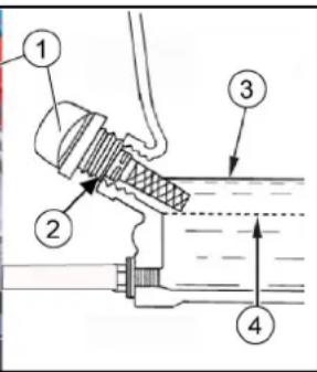
①Pipa za gorivo
②O-obroč
③Bazen za usedline
-
Odvijte bazen za usedline.
-
Odstranite o-obroč.
-
Bazena za usedline ne čistite z nevnetljivim topilom.
-
Bazen za usedline temeljito posušite.
-
O-obroč vstavite v ohišje.
-
Privijte in zategnite bazen za usedline.
-
Pipo za gorivo obrnite v položaj ON.
-
Preverite, ali je bazen za usedline tesen.
10.Pipo za gorivo obrnite v položaj OFF.
Preverjanje, nastavljanje vžigalne svečke
Slika brez pokrova motorja
①Zadnje kolo
②Kolesna matica (4x)
③Simbol oporne točke
- Napravo ustavite na ravni površini in izklopite motor.
a Preverite, ali je podlaga stabilna.
b Napravo zavarujte pred nenamernim premikanjem.
natural_image
Close-up of a cleaning brush head with yellow and black bristles, labeled parts ① and ② (no text or symbols on the brush itself)①Stranske metle
②Vijaki
- Parkirajte napravo.
- Na spodnji strani odvijte 3 vijake.
- Snemite stransko metlo.
- Po potrebi očistite nosilec.
- Na sojemalnik namestite novo stransko metlo in jo privijte z vijaki.
natural_image
Mechanical cleaning device showing a brush head with yellow filter blades and a close-up of the blade structure (no text or symbols visible)①Pritrditev
②Stranska tesnilna letev
①Pokrov
②Prijemna vdolbina
③Ročica filtra za prah
④Filter za prah (okrogli filter)
1. Parkirajte napravo.
2. Počakajte vsaj 1 minuto, da se prah poleže.
3. Pokrov na prijemni vdolbini zasukajte navzgor.
4. Ročico filtra za prah premaknite v desno.
5. Filter za prah odstranite navzgor.
6. Po potrebi: Filter za prah očistite (izsesajte ali previdno okrcajte) ali vstavite nov filter za prah.
- Namestite sornike.
a Sornike vstavite v izvrtine.
b Vzmetne zatiče vstavite v izvrtine sornikov, dokler se vzmetni zatiči ne zaskočijo.
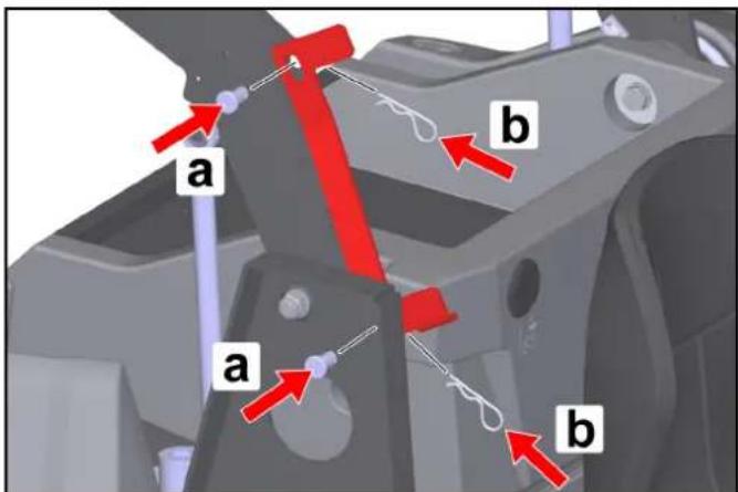
POZOR
natural_image
Diagram of a cleaning or cleaning machine with a highlighted interior component and a red arrow indicating the process (no text or symbols present)- Napravo parkirajte in jo zavarujte pred nenamernim premikanjem.
- Odklopite negativni pol baterije.
- Odvijte 5 vijakov sprednjega pokrova.
- Snemite pokrov.
- S pomočjo tabele prepoznajte okvarjeno varovalko naprave.
- Zamenjajte pokvarjene varovalke naprave.
- Ponovno namestite pokrov.
- Ponovno priključite negativni pol baterije.
Varovalke naprave (pregled)
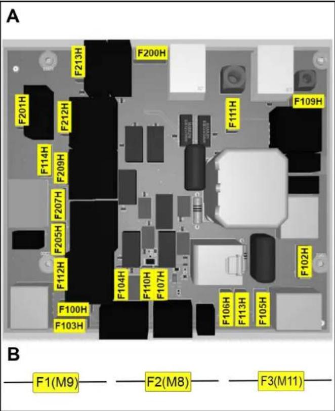
B: Varovalke v kabelskem snopu (nosilec varovalk)
| Varovalka naprave Vrednost (A) Poimenovanje | ||
| F1 (M9) 7,5 Motor za | dviganje | |
| F2 (M8) 7,5 Motor za | dviganje | |
| F3 (M11) 7,5 Motor za | dviganje | |
2006/42/ES (+2009/127/ES)
2014/30/EU
2000/14/ES
2014/53/EU (TCU)
Chairman of the Board of Management

S. Reiser
Director Regulatory Affairs & Certification
Winnenden, 1. 6. 2021
Cuprins
① Carcasa dreapta (pivotant)
①Deplasare
natural_image
3D rendering of a cleaning or cleaning robotic vehicle with visible door, wheels, and yellow safety clips (no text or symbols)natural_image
3D rendering of a cleaning or cleaning robotic device with labeled parts (no text or symbols visible)natural_image
3D diagram of a car chassis on a platform with a light bulb and directional arrows indicating motion (no text or symbols)natural_image
Interior view of a medical imaging machine showing the seating and internal components (no text or symbols visible)① Robinet de combustibil
①Deblocarea frânei de parcare
②Frână de parcare
natural_image
3D rendering of a robotic car interior showing front and side views with no visible text or symbols①Jojă de ulei
②Orificiu de umplere cu ulei
③ nivel superior ulei (MAX)
④ nivel inferior ulei (MIN)
①Piuliță cu aripi
②Capac
③ Filtru de aer
④ Suport de fixare
① Roată posterioară
① Mătură laterală
②Suruburi
①Surubul randalinat, stânga
②Placa de aşezare
③Placa de acoperire
④Surubul randalinat, dreapta
natural_image
Close-up of a cleaning or cleaning machine component with three labeled parts (1, 2, 3), showing blade and brush patterns (no text or symbols beyond labels)①Capac
- Montati bolturile.
natural_image
Diagram of a cleaning or cleaning machine with a close-up inset showing internal components and a red arrow indicating cleaning direction (no text or symbols present)Directive UE relevante
2006/42/UE (+2009/127/UE)
2014/30/UE
2000/14/UE
2014/53/EU (TCU)
Norme armonizate aplicate
EN 60335-1
EN 60335-2-72
EN 55012: 2007 + A1: 2009
EN 62233: 2008
TCU
EN 301 511 V12.5.1
EN 300 440 V2.1.1
EN 300 328 V2.2.2
EN 300 330 V2.1.1

H. Jenner
Chairman of the Board of Management

S. Reiser
Director Regulatory Affairs & Certification
71364 Winnenden (Germania)
Tel.: +49 7195 14-0
Fax: +49 7195 14-2212
Winnenden, 2021/06/01
Sadržaj
Opće napomene 370
Pravilna uporaba.... 371
Funkcija.... 372
Sigurnosni napuci 372
①Oplata s desne strane (zakretljiva)
② Sigurnosni podupirač spremnika skupljene prljavštine
①Upravljač
①Vožnja
– Motor se može pokrenuti u ovom položaju
natural_image
3D rendering of a cleaning or cleaning robotic vehicle with visible door, wheels, and yellow safety tags (no text or symbols)- Da biste otvorili poklopac motora, uhvatite udubljene za držanje sprijeda, odblokirajte ga prema gore, a zatim zakrenite u stranu.
Otvaranje / zatvaranje oplate s desne strane
Oplata s desne strane mora se otvoriti za određene aktivnosti:
natural_image
3D rendering of a cleaning or anti-shelfer machine with labeled components (no text or symbols visible)- Da biste otvorili oplatu, uhvatite udubljene za držanje, odbloki-rajte ga prema gore, a zatim zakrenite u stranu.
The Ground Truth image displays a single, solid horizontal line. According to Rule 2 (UNDERSCORE & LINE RULES), this is a stylistic or background line, not a placeholder underscore. Therefore, the OCR result must ignore it and output nothing or only meaningful text. The provided OCR content is "____", which consists of four underscores. This is an incorrect interpretation of the line as a placeholder, violating the rule that stylistic lines must be ignored. The OCR has hallucinated placeholder underscores where none exist in the GT. Hence, the OCR result is inconsistent with the Ground Truth.

Upozorenje

Zbrinjavanje
natural_image
Mechanical assembly diagram showing a motor on a platform with rotating components and a light bulb (no text or symbols)Slika: Silazna rampa
- Spojite akumulator i po potrebi ga napunite.
- Pomoću priloženih dasaka napravite rampu prema skici.
- Izrežite plastične trake za pakiranje i uklonite ambalažnu foliju.
- Uklonite zatezne trake pričvršćene za granične točke.
- Odvijte tri prikazane podne daske i drvenu gredicu na paleti.
- Daske položite na rub palete, pritom ih postavite tako da se nalaze ispred kotača uređaja. Vijcima pričvrstite daske.
- Stavite drvenu gredicu ispod dasaka kao potporu.
- Uklonite drvene blokove koji drže kotače.
- Otpustite pozicijsku kočnicu.
- Pažljivo odvezite uređaj s palete preko rampe koju ste napravili (vidi poglavlje „Pomicanje uređaja s vlastitim pogonom) ili ga gurajte s palete (vidi poglavlje „Pomicanje uređaja bez vlastitog pogona“).
Otvaranje / zatvaranje poluge za slobodni hod
△OPASNOST
①Poluga slobodnog hoda, crvena
②Položaj slobodni hod je zatvoren
– U r e daj je spreman za vožnju
③Položaj slobodni hod je otvoren – U r e daj se može pomicati
Pomicanje uređaja bez vlastitog pogona (uredaj se može pomicati)
1 Za pomicanje uređaja otvorite polugu slobodnog hoda.
a Zakrenite desnu oplatu prema van.
b Povucite polugu slobodnog hoda prema tijelu (otvaranje).
c Otpustite pozicijsku kočnicu.
d Pomaknite uređaj.
Pomicanje uređaja s vlastitim pogonom (uredaj je spreman za vožnju)
1 Nakon pomicanja uređaja zatvorite polugu slobodnog hoda.
a Pritisnite pozicijsku kočnicu.
b Odgurajte polugu slobodnog hoda od tijela (zatvaranje).
c Zatvorite desnu oplatu.
Montaža bočne metle
Napomena
①Spremnik goriva
②Poklopac spremnika
③Prikaz napunjenosti spremnika goriva
- Isključite uređaj (isključite motor).
-
Zakrenite poklopac motora prema van.
-
Otvorite poklopac spremnika.
-
Natočite gorivo.
-
Obrišite gorivo koje se prelilo i zatvorite poklopac spremnika.
Namještanje sjedala vozača
△OPASNOST
Opasnost od nezgode
natural_image
Interior view of a modern vehicle cockpit with labeled parts (no text or symbols visible)①Slavina za gorivo
1 Da biste otvorili odn. zatvorili slavinu za gorivo, okrenite je u odgovarajućem smjeru do graničnika.
Pritiskanje / otpuštanje pozicijske kočnice
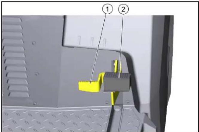
④ donja razina ulja (MIN)
- Uređaj zaustavite na ravnoj površini.
- Ostavite motor da se ohladi.
a Provjerite razinu motornog ulja najranije 5 minuta nakon isključivanja motora.
① Krilna matica
②Poklopac
③Filtar za zrak
④ Učvršćenje
-
Skinite poklopac.
-
Provjerite je li filtar zraka onečišćen te ga po potrebi očistite.
-
Gurnite poklopac u držač, a zatim ga stavite. a Obratite pažnju na ispravan položaj u učvršćenju.
-
Postavite krilnu maticu i pritegnite je.
①Brtva
② Krilna matica poklopca
③Poklopac
④ Krilna matica filtra za zrak
①Slavina za gorivo
②O-prsten
③Posuda za taloženje
-
Odvrnite posudu za taloženje.
-
Skinite O-prsten.
-
Očistite posudu za taloženje u nezapaljivom otapalu.
-
Temeljito obrišite posudu za taloženje.
-
Stavite O-prsten u kućište.
-
Uvrnite posudu za taloženje i pritegnite je.
-
Slavinu za gorivo zakrenite u položaj „ON“ (uključeno).
-
Provjerite da posuda za taloženje sjedi čvrsto i ne propušta.
10.Slavinu za gorivo zakrenite u položaj „OFF“ (isključeno).
① Ključ za svjećice
②0,7...0,8 mm
③Brtva
④Svjećica
Slika bez poklopca motora
① Spremnik hidrauličkog ulja
② Poklopac odzračnika / otvor za punjenje
③ Filtar hidrauličkog ulja
①Stražnji kotač
②Matica kotača (4x)
③Simbol prihvatne točke
- Uređaj parkirajte na ravnoj površini.
a Provjerite da je podloga stabilna.
b Osigurajte uređaj protiv pomicanja.
c Otvorite bočnu oplatu odn. poklopac motora. - Postavite dizalicu za podizanje vozila na označenim prihvatnim točkama na okviru.
- Otpustite matice kotača s pomoću prikladnog alata za otprilike 1 okret.
- Uređaj podignite pomoću dizalice za podizanje vozila.
- Odvijte i izvadite matice kotača.
- Skinite kotač.
- Neispravni kotač treba popraviti specijalna radionica ili ga treba zamijeniti.
- Postavite kotač, uvijte matice kotača do kraja i lagano ih zate- gnite.
- Spustite uređaj s dizalicom za podizanje vozila.
10.Zatvaranje bočne oplate odn. poklopca motora - Pritegnite matice kotača potrebnim okretnim momentom (56 Nm).
①Bočna metla
②Vijci
- Odložite uređaj.
- Odvrnite 3 vijka s donje strane.
- Skinite bočnu metlu.
-
Po potrebi očistite prihvatnik.
-
Nataknite novu bočnu metlu na zahvatnik i pričvrstite ju vijcima.
natural_image
Technical illustration of a cleaning or dust removal device with labeled components (1, 2, 3), showing blade blades and internal structure (no text or symbols beyond labels)①Pričvršćivanje
②Bočna brtvena letvica
③Prednja brtvena letvica
④Stražnja brtvena letvica
①Poklopac
②Udubljenje za držanje
③Poluga filtra za prašinu
- Ugradite svornjake.
a Umetnite svornjake u provrte.
natural_image
Diagram of a cleaning or cleaning vehicle with a broom and brush, showing internal components and a red arrow indicating action (no text or symbols present)- Parkirajte uređaj i osigurajte ga od ponovnog uključivanja.
- Skinite stezaljku s minus pola akumulatora.
- Odvrnite 5 vijaka iz prednjeg poklopca.
- Skinite poklopac.
- Identificirajte pomoću tablice neispravan osigurač uređaja.
- Zamijenite neispravni osigurač uređaja.
- Ponovno postavite poklopac.
- Ponovno spojite negativni pol akumulatora.
Osigurači uređaja (pregled)

A: Osigurači na elektroničkom upravljanju
| Osigurač uređaja | Vrijednost (A) | Oznaka |
| F100H 7,5 Sklopka s | ključem | |
| F102H 7,5 Radno svjetlo | ||
| F103H 7,5 Pumpa za | vodu | |
| F104H 3 LED | ||
| F105H 7,5 Radno svjetlo | ||
| F106H 3 Plavo svjetlo | ||
| F107H 1 Brojač | ||
| F109H 5 Motor filtra | ||
| F110H 7,5 Sirena | ||
| F111H 10 Motori za podizanje | ||
| F112H 5 Pokretanje motora | ||
| F113H 1 Rotacijska signalna | svjetiljka | |
| F114H 1 Senzor položaja pra- | žnjenja | |
| F200H 30 Glavni osigurač | ||
| F201H 3 Glavni ventil | K1 | |
| F205H 3 Jedinice za | metenje | K4 |
| F207H 3 Otvaranje zaklopke | K6 | |
| F209H 3 Zatvaranje zaklopke | K3 | |
| F212H 3 Podizanje K5 | ||
| F213H 3 Spuštanje K2 | ||
B: Osigurači u kabelskom svežnju (držač osigurača)
| Osigurač uređaja | Vrijednost (A) | Oznaka |
| F1 (M9) 7,5 Motor za | podizanje | |
| F2 (M8) 7,5 Motor za | podizanje | |
| F3 (M11) 7,5 Motor za | podizanje |
2006/42/EZ (+2009/127/EZ)
2014/30/EU
2000/14/EZ
2014/53/EU (TCU)
Primijenjene uskladene norme
EN 60335-1
EN 60335-2-72
EN 55012: 2007 + A1: 2009
EN 62233: 2008
TCU
EN 301 511 V12.5.1
EN 300 440 V2.1.1
EN 300 328 V2.2.2
EN 300 330 V2.1.1
Primijenjene nacionalne norme

H. Jenner
Chairman of the Board of Management

S. Reiser
Director Regulatory Affairs & Certification
Opunomoćenik za dokumentaciju:
S. Reiser
Alfred Kärcher SE & Co. KG
Alfred-Kärcher-Str. 28 - 40
71364 Winnenden (Njemačka)
Tel.: +49 7195 14-0
Telefaks: +49 7195 14-2212
Winnenden, 01.06.2021.
Sadržaj
Opšte napomene 388
Namenska upotreba 389
Funkcija 389
Sigurnosne napomene.... 389
Opis uređaja 390
Pre puštanja u pogon.... 392
Puštanje u pogon.... 393
Rad 394
Transport 395
Skladištenje 396
① Kućište desno (zakretno)
② Osiguravanje podupirača za posudu za nakupljenu prljavštinu
③ Sedišta vozača (sa kontaktnim prekidačem sedišta)
④Rotaciona signalna svetiljka
⑤Poklopac motora (zakretni)
⑥Taster za podizanje/pražnjenje posude za nakupljenu prljavštinu
⑦ Noseća šina za "Hombase System"
⑧Otpuštanje kočnice
⑨Parkirna kočnica
⑩Zadnji točak
⑪Valjak za metenje sa zaptivnim trakama
⑫Bočna metla, levo*
⑬Prednji točak
⑭Pedala za podizanje / spuštanje zaklopke za grubu prljavštinu
⑮Bočna metla, desno
⑯Papučica pedale napred/nazad
⑰Poluga za podešavanje sedišta
⑱ Elementi za rukovanje**
⑲Upravljač
* samo KM 100/120 R G 2SB
** detaljnije opisano u jednom od kasnijih poglavlja
Opciono
Nije prikazana sledeća oprema koja je već ugrađena prilikom poručivanja ili se može naknadno ugraditi u servisu.
1 Udobno sedište
2 Radno svetlo
3 Komplet u skladu sa Zakonom o drumskom saobraćaju
4 Blue Spot
①Upravljač
② Prekidač radno svetlo (opcija)
③ Prekidač za rotaciono signalno svetlo (opcija)
④Sirena
⑤ Prekidač sa ključem
⑥Pedala za vožnju napred
⑦Pedala za vožnju unazad
⑧Prigušna poluga
⑨Taster za visoko pražnjenje
⑩ Taster za čišćenje filtera za prašinu
⑪ Prekidač sistema za raspršivanje vode (opcija)
⑫ Prekidač za odabir programa*
⑬Brojač radnih sati
* opisuje se još opširnije u sledećem poglavlju
Prekidač za odabir programa
Napomena
①Vožnja
natural_image
3D rendering of a cleaning or cleaning machine with visible door, wheels, and directional arrows indicating motion (no text or symbols)- Radi otvaranja, poklopac motora uhvatite napred na udubljenju za držanje, otključajte ga sa gornje strane i zatim zakrenite na stranu.
natural_image
3D rendering of a cleaning or cleaning robotic device with directional arrows indicating motion (no text or symbols)- Radi otvaranja, oplatu uhvatite napred na udubljenju za držanje, otključajte je sa gornje strane i zatim zakrenite na stranu.
natural_image
3D diagram of a vehicle chassis mounted on a rail track with a light bulb and directional arrows indicating motion (no text or symbols)Slika: Silazna rampa
- Priključiti akumulator i napuniti ga po potrebi.
- Pomoću priloženih dasaka napravite rampu u skladu sa skicom.
- Isecite trake za pakovanje od plastike i uklonite foliju za pakovanje.
- Uklonite pričvršćivače zatezne trake na tačkama za sidrenje.
- Odviti zavrtnje na tri označene podne daske i drvenoj kocki na paleti.
- Daske položiti na ivicu palete i usmeriti tako da se nalaze ispred točkova uređaja. Čvrsto stegnite daske.
- Podmetnite drvenu kocku kao potporu ispod dasaka.
- Uklonite drvene klocne za blokiranje točkova.
- Otpustite parkirnu kočnicu.
- Uređaj pažljivo odvesti sa palete preko postavljene rampe (pogledati poglavlje "Pomeranje uređaja sa sopstvenim pogonom") ili ga gurnite sa palete (pogledajte poglavlje "Pomeranje uređaja bez sopstvenog pogona").
Otvaranje / zatvaranje poluge za slobodan hod
△OPASNOST
①Poluga za slobodni hod, crvena
②Položaj za slobodni hod zatvoren – U r e daj se spreman za vožnju
③Položaj za slobodni hod je otvoren
– U r e daj može da se pomera
①Rezervoar za gorivo
② Zatvarač rezervoara za gorivo
③Prikaz rezervoara
natural_image
Interior view of a medical imaging machine showing the seating and internal components (no text or symbols visible)①Sedište vozača
②Poluga za podešavanje sedišta
-
Polugu za pomeranje sedišta povucite nadesno i sedište vozača pomerite u željeni položaj.
-
Pustite polugu za pomeranje sedišta.
-
Pomeranjem sedišta vozača napred i unazad proverite da li se poluga pravilno uklopila.
Otvaranje/zatvaranje slavine za gorivo

① Deblokada ručne kočnice
② Ručna kočnica
①Upravljač
②Vozite napred
③Vozite nazad
④ Ručna kočnica
⑤Poklopac za grubu prljavštinu
- Pažljivo aktivirajte pedalu gasa.
a Pedalom za vožnju se kontinualno reguliše brzina vožnje.
b Izbegavajte naglo pritiskanje pedale.
①Taster za visoko pražnjenje
② Prekidač za podizanje/spuštanje posude za nakupljenu prljavštinu
③ Prekidač za otvaranje/zatvaranje poklopca posude
-
Prekidač za odabir programa postavite u položaj „Vožnja“ (posuda za nakupljenu prljavštinu se može podići samo u ovom položaju).
-
Grubo pozicionirajte uređaj.
a Nakon isključivanja uređaja sačekajte barem 1 minut da bi se pre pražnjenja slegla prašina.
- Pritisnite i držite pritisnut taster za visoko pražnjenje na komandnom polju.
- Pritisnite prekidač posude za nakupljenu prljavštinu i podignite posudu za nakupljenu prljavštinu.
a Radi pražnjenja u kontejneru za otpad, posudu za nakupljenu prljavštinu podignite do kraja i lagano je približite sabirnoj posudi.
b Radi slobodnog pražnjenja, posudu za nakupljenu prljavštinu podignite otprilike do sredine, sve dok se ne može otvoriti poklopac posude (kod manje visine pražnjenja je blokirano aktiviranje poklopca posude).
- Aktivirajte ručnu kočnicu.
- Pritisnite prekidač na poklopcu posude i ispraznite posudu za nakupljenu prljavštinu.
- Zatvorite poklopac posude.
- Otpustite ručnu kočnicu.
- Udaljite se od mesta pražnjenja.
10.Spustite do kraja posudu za nakupljenu prljavštinu.
natural_image
3D rendering of a robotic cleaning device showing front and side views with no visible text or symbols①Šipka za merenje ulja
②Otvor za punjenje ulja
③gornji nivo ulje (MAX)
④ donji nivo ulje (MIN)
- Uređaj odložiti na ravnu površinu.
- Ostavite motor da se ohladi.
a Izvršite proveru nivoa ulja u motoru najranije 5 minuta nakon isključivanja motora.
- Otvorite desnu oplatu.
- Odvrnite šipku za merenje nivoa ulja i očitajte nivo ulja.
a Ako je nivo ulja ispod oznake MIN, dopunite motorno ulje. Vrstu ulja pogledajte u poglavlju "Tehnički podaci".
b Nemojte prepunjavati, dopunite samo do oznake MAX.
- Ako je nivo ulja tačan, okrenite šipku za merenje ulja.
- Zatvorite oplatu.
Zamena ulja
Zamenu ulja izvršite kada je motor zagrejan da bi ulje bolje proticalo.
- Isključite motor.
- Uređaj odložite na ravnoj površini.
- Pripremite odgovarajuću prihvatnu posudu za staro ulje.
- Otvorite (zakrenite) desnu oplatu.
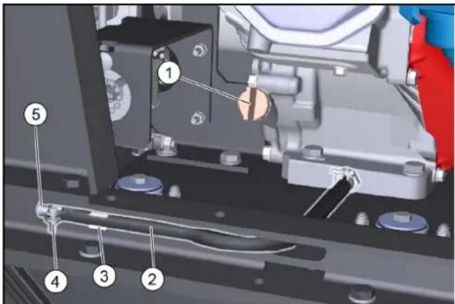
①Šipka za merenje ulja / otvor za punjenje ulja
②Ispusno crevo
③Držač za ispusno crevo
④ Stezaljka za crevo
⑤Element za zatvaranje
- Odvrnite šipku za merenje nivoa ulja.
- Crevo za ispuštanje izvucite iz držača.
- Otvorite obujmice za crevo na ispusnom crevu i izvucite element za zatvaranje.
- Pustite da ulje iscuri do kraja u prihvatnu posudu.
- Postavite element za zatvaranje i pritegnite ga obujmicom za crevo.
- Novo motorno ulje (pogledajte odeljak „Tehnički podaci“) treba napuniti do donje ivice otvora za punjenje ulja.
11.Postavite šipku za merenje nivoa ulja i zategnite je.
12.Zatvorite oplatu.
13.Staro ulje odložite na otpad u skladu sa ekološkim propisima.
Provera filtera za vazduh
①Leptirasta navrtka
②Poklopac
③Filteri za vazduh
④Fiksiranje
- Skinite poklopac.
- Proverite da li je filter za vazduh zaprljan i po potrebi ga očistite.
- Ugurajte poklopac u deo za fiksiranje, pa ga postavite. a Vodite računa o ispravnom položaju u delu za fiksiranje.
- Postavite leptirastu navrtku i zategnite je.
Čišćenje filtera za vazduh
- Odvrnite leptirastu navrtku na poklopcu.
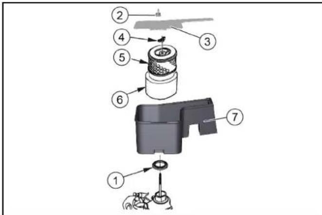
①Zaptivka
②Leptirasta navrtka poklopca
③Poklopac
④Leptirasta navrtka filtera za vazduh
⑤Uložak papirnog filtera
⑥Uložak filtera za penu
⑦ Kućište filtera za vazduh
2. Skinite poklopac.
3. Odvrnite leptirastu navrtku filtera za vazduh.
4. Skinite uložak filtera za vazduh.
5. Skinite uložak filtera za penu sa uloška papirnog filtera.
6. Proverite da li ima oštećenja uložaka filtera za vazduh.
7. Zamenite oštećene uloške filtera za vazduh.
8. U slučaju dalje upotrebe očistite uloške filtera za vazduh.
9. Uložak papirnog filtera istresite udaranjem nekoliko puta na tvrdoj podlozi i izduvajte ga iznutra komprimovanim vazduhom (maksimalno 0,2 MPa).
10.Uložak filtera za penu:
a O čistite u toploj sapunici.
b Isperite čistom vodom.
c lli očistite nezapaljivim rastvaračem.
d Ostavite da se osuši.
e Potopite u čisto motorno ulje.
f Istisnite prekomerno ulje.
- Unutrašnju stranu poklopca i kućišta filtera za vazduh obrišite vlažnom krpom. Vodite računa o tome da u motor ne dospe prljavština.
12.Uložak filtera za penu postavite na uložak papirnog filtera.
13.Uložak filtera za vazduh postavite u kućište filtera za vazduh. - Vodite računa o tome da je postavljena zaptivka između kućišta filtera za vazduh i motora.
- Postavite leptirastu navrtku filtera za vazduh i zategnite je.
- Postavite poklopac.
- Postavite leptirastu navrtku poklopca i zategnite je.
Čišćenje taložnika
- Zakrenite slavinu za gorivo u položaj „OFF“.
① Ključ za svećice za paljenje
②0,7...0,8 mm
③Zaptivka
④Svećica za paljenje
- Zamenite svećicu za paljenje sa istrošenim elektrodama ili polomljenim izolatorom.
- Proverite stanje elektrode svećice za paljenje. Zadata vrednost 0,7...0,8 mm.
- Proverite da li ima oštećenja na zaptivci svećice za paljenje.
PAŽNJA
Slika bez poklopca motora
①Rezervoar ulja hidraulike
② Poklopac za odzračivanje / otvor za punjenje
③Filter za ulje hidraulike
- Odložiti uređaj.
- Otvorite poklopac motora.
- Proverite nivo ulja hidraulike kada je motor hladan.
natural_image
3D mechanical component with a yellow and gray brush head, showing internal structure and assembly details (no text or symbols)①Valjak za metenje
②Prihvatnik valjka za metenje
③ Usmerenost dlačica u smeru vožnje napred
- Proverite da li ima istrošenosti i da li ima umotanih traka.
- Ako je potrebno: ugraditi novi valjak za metenje.
- Prilikom ugradnje vodite računa o ispravnom usmerenju dlačica (prihvatnici valjaka za metenje su identični).
- Pokrivku i ploču ležaja montirati obrnutim redosledom.
① Pričvršćivanje
②Bočna zaptivna lestvica
③Prednja zaptivna traka
④Zadnja zaptivna traka
- Otpustite pričvršćenje zaptivnih traka.
- Podesite zaptivnu traku pomeranjem u uzdužnim otvorima. a Pogledajte vrednosti u tabeli.
- Ako su podešavanja tačna, pričvrstite zaptivne trake.
Provera / zamena filtera za prašinu
△OPASNOST
Opasnost za zdravlje zbog prašine
Nosite masku za zaštitu od prašine i zaštitne naočare prilikom izvođenja radova na filterskom sistemu.
Obratite pažnju na sigurnosne propise pri postupanju sa finim prašinama.
①Poklopac
②Udubljenje za držanje
③Poluga filtera za prašinu
④Filter za prašinu (okrugli filter)
-
Odložiti uređaj.
-
Sačekajte barem 1 minut da se prašina slegne.
- Zakrenite nagore poklopac na udubljenju za držanje.
- Polugu filtera za prašinu pomerite nadesno.
- Filter za prašinu izvaditi prema gore.
- Ako je potrebno: Filter za prašinu očistiti (usisati ili pažljivo istresti) ili umetnuti novi filter za prašinu.
Sigurnosni podupirač za ugradnju / uklanjanje posude za nakupljenu prljavštinu
Montaža:
- Odložiti mašinu na stabilnoj, vodoravnoj podlozi.
- Potpuno podignuti posudu za nakupljenu prljavštinu, vidi poglavlje Pražnjenje posude za nakupljenu prljavštinu.
- Isključiti mašinu, vidi poglavlje Isključivanje uređaja.
- Otvoriti desnu oplatu, vidi poglavlje Otvaranje/zatvaranje oplate desno.
- Uklonite sigurnosni podupirač.
a Izvucite opružne čepove iz zavrtnja.
b Izvucite zavrtnje i uklonite sigurnosni podupirač na sparu.
natural_image
Close-up of a cleaning machine with a broom and yellow brush, showing internal components and a red upward arrow (no text or symbols)- Isključite uređaj i zaštitite ga od otkotrljavanja.
- Odvojite negativni pol akumulatora.
- Odvijte 5 zavrtanja prednjeg poklopca.
- Skinite poklopac.
- Identifikujte neispravni osigurač uređaja na osnovu tabele.
- Zamenite neispravne osigurače.
- Ponovo postavite poklopac.
- Ponovo priključite negativni pol akumulatora.
Osigurači uređaja (pregled)

A: Osigurači na električnom upravljanju
| Osigurači uređaja | Vrednost (A) | Oznaka |
| F100H 7,5 Prekidač sa ključem | ||
| F102H 7,5 Radno svetlo | ||
| F103H 7,5 Pumpa za vodu | ||
| F104H 3 LED | ||
| F105H 7,5 Radno svetlo | ||
| F106H 3 Blue Spot | ||
| F107H 1 Brojač | ||
| F109H 5 Filter motora | ||
| F110H 7,5 Radna sirena | ||
| F111H 10 Podizni motori | ||
| F112H 5 Pokretanje motora | ||
| F113H 1 Rotaciona signalna | svetiljka | |
| F114H 1 Pražnjenje senzora | položaja | |
| F200H 30 Glavni osigurač | ||
| F201H 3 K1 Glavni ventil | ||
| F205H 3 K4 Agregati za | metenje | |
| F207H 3 K6 Otvaranje | poklopca | |
| F209H 3 K3 Zatvaranje | poklopca | |
| F212H 3 K5 Podizanje | ||
| F213H 3 K2 Spuštanje | ||
B: Osigurači na kablovskom stablu (držač osigurača)
| Osigurači uređaja | Vrednost (A) | Oznaka |
| F1 (M9) 7,5 Podizni motori | ||
| F2 (M8) 7,5 Podizni motori | ||
| F3 (M11) 7,5 Podizni motori |
| Greška Otklanjanje | |
| Motor se ne pokreće. | Proverite / napunite bateriju pokretača.Prekidač sa ključem u položaju "I - ON".Prekidač za odabir programa u položaju "Vožnja"Na niskim spoljašnjim temperaturama: Aktivirajte polugu prigušnice.Sedite na sedište vozača (kontaktni prekidač sedišta se aktivira).Zatvorite do kraja poklopac motora i desnu oplatu.Proverite nivo motornog ulja, po potrebi dopunite motorno ulje.Sipajte gorivo.Otvorite slavinu za gorivo.Proverite svećicu za paljenje. |
| Motor radi neravnomerno | Proverite nivo napunjenosti rezervoara goriva.Proverite položaj poluge prigušnice.Proverite priključke i vodove u sistemu goriva.Proverite / zamenite svećice za paljenje.Očistite / zamenite filter za vazduh. |
| Motor radi, ali uređaj ne ili veoma sporo | Otpustite ručnu kočnicu.Proverite položaj poluge za slobodni hod.Proverite / dopunite nivo u rezervoaru hidrauličkog ulja.Kada je temperatura u minusu i ulje hidraulike hladno: Najmanje 3 minuta ostavite uređaj da se zagreva. |
| Motor se ne isključuje (prekidač za odabir programa i prekidač sa ključem su u položaju OFF) | Benzinski motor:a Otvorite poklopac motora (oprez zbog rotirajućeg klinastog remena).b Zatvorite slavinu za gorivo. |
| Prašina prilikom metenja / nedovoljna snaga usisavanja | Ispraznite posudu za nakupljenu prljavštinu.Proverite / očistite/ zamenite filter za prašinu.a Proverite ispravno naleganje filtera za prašinu.b Filter za prašinu očistite, ako je blago zaprljan.c Filter za prašinu zamenite, ako je oštećen ili jako zaprljan.Proverite istrošenog zaptivne trake u oblasti metenja. Po potrebi dodatno podesiti odnosno zameniti.Proverite / zamenite zaptivke na filterskoj kaseti.Proverite / zamenite zaptivne trake na posudi za nakupljenu prljavštinu. |
| Rezultat čišćenja nije zadovoljavajući | Valjak za metenje i bočnu metlu proverite na znakove istrošenosti i zamenite ih, ako je potrebno.Zaptivne lestvice proverite na znakove istrošenosti i podesite / zamenite ih, ako je potrebno.Proverite funkciju poklopca za grubu prljavštinu.Zatvoriti poklopac za metenje mokrih površina.Proverite nivo napunjenosti rezervoara ulja hidraulike.Proverite zaptivenost hidrauličkog sistema. |
| Valjak za metenje / bočna metla se ne okreću | Okrenite prekidač za odabir programa na željeni program "Metenje".Proverite nivo napunjenosti rezervoara ulja hidraulike.Proverite zaptivenost hidrauličkog sistema.Proveriti da li ima umotanih traka na valjku za metenje / bočnoj metli.Kontaktirajte servisnu službu. |
| Pražnjenje posude za nakupljenu prljavštinu ne funkcioniše | Zavrtanj za sigurnosni element na smicanje na posudi za nakupljenu prljavštinu je osiguran, zamenite polomljeni zavrtanj.Kontaktirajte servisnu službu. |
| Desna oplata se ne može zatvoriti | Posuda za nakupljenu prljavštinu je obezbeđena sigurnosnim podupiračem. Demontirajte sigurnosni podupirač (pogledajte poglavlje Sigurnosni podupirač za ugradnju / uklanjanje posude za nakupljenu prljavštinu). |
Pribor / rezervni delovi
2006/42/EZ (+2009/127/EZ)
2014/30/EU
2000/14/EZ
2014/53/EU (TCU)
Primenjene harmonizovane norme
EN 60335-1
EN 60335-2-72
EN 55012: 2007 + A1: 2009
EN 62233: 2008
TCU
EN 301 511 V12.5.1
EN 300 440 V2.1.1
EN 300 328 V2.2.2
EN 300 330 V2.1.1
Primenjene nacionalne norme
Chairman of the Board of Management

S. Reiser
Director Regulatory Affairs & Certification
Lice ovlašćeno za dokumentaciju:
S. Reiser
Alfred Kärcher SE & Co. KG
Alfred-Kärcher-Str. 28 - 40
71364 Winnenden (Germany)
Tel.: +49 7195 14-0
Winnenden, 2021/06/01
Περιεχόμενα
①Κίνηση
natural_image
3D rendering of a cleaning or cleaning service robot with visible door, wheels, and directional arrows indicating motion (no text or symbols)natural_image
3D rendering of a gray industrial cleaning or cleaning machine with visible wheels and control panel (no text or symbols)natural_image
3D diagram of a mechanical assembly with rotating components and a light bulb, no visible text or symbolsΣχήμα: Ράμπα
natural_image
Interior view of a medical imaging machine with labeled parts (1 and 2), showing no visible text or symbols beyond labels.natural_image
3D rendering of a robotic car with front and side views, showing no text or symbolsΣχήμα χωρίς καπό
①Πίσω τροχός
①Πλαϊνή σκούπτα
②Βίδες
natural_image
Technical illustration of a cleaning or dust removal device with labeled components (1, 2, 3), showing blade blades and internal structure (no text or symbols beyond labels)①Στήριγμα
①Κάλυμμα
natural_image
Diagram of a cleaning or cleaning machine with a close-up inset showing internal components and a red arrow indicating motion (no text or symbols present)Chairman of the Board of Management

S. Reiser
Director Regulatory Affairs & Certification
71364 Winnenden (Germany)
Tηλ.: +49 7195 14-0
Φαξ: +49 7195 14-2212
Winnenden, 2021/06/01
Содержание
Общие указания 424
①Движение
natural_image
3D rendering of a cleaning or cleaning service robot with visible door, wheels, and directional arrows indicating motion (no text or symbols)natural_image
3D rendering of a cleaning or cleaning robotic device with visible wheels and control panel (no text or symbols)natural_image
3D diagram of a car chassis on a platform with a light bulb and directional arrows indicating motion (no text or symbols)natural_image
Interior view of a medical imaging machine showing the seating and internal components (no text or symbols visible)natural_image
3D rendering of a robotic cleaning device showing front and side views with labeled components (no text or symbols present)natural_image
Mechanical assembly diagram showing a motor or gear mechanism with no visible text or symbols
①Топливный кран
①Свечной ключ
②0,7-0,8 MM
③Уплотнение
④Свеча зажигания
natural_image
Technical illustration of a street cleaning machine with three labeled components (1, 2, 3), showing blade blades and mesh texture (no text or symbols beyond labels)- Установить болты.
natural_image
Diagram of a cleaning or cleaning machine with a close-up inset showing internal components and a red arrow indicating the process (no text or symbols present)
H. Jenner
Chairman of the Board of Management

S. Reiser
Director Regulatory Affairs & Certification
71364 Winnenden (Germany)
Тел.: +49 7195 14-0
Факс: +49 7195 14-2212
①Pyx
natural_image
3D rendering of a cleaning or cleaning service robot with visible door, wheels, and directional arrows indicating motion (no text or symbols)natural_image
3D rendering of a cleaning or cleaning service robot with labeled parts (no text or symbols visible)natural_image
3D diagram of a car chassis mounted on a platform with a light bulb and curved arrows indicating motion (no text or symbols)Рисунок: Рампа
natural_image
Interior view of a medical imaging machine with labeled parts (1 and 2), showing no visible text or symbols beyond labels.①Кермове колесо
②Рух уперед
③Рух назад
④Стоянкове гальмо
natural_image
3D rendering of a robotic cleaning device showing front and side views with no visible text or symbols①Щуп
Рисунок без капота
①Бічна щітка
②ВИНТИ
natural_image
Technical illustration of a cleaning or dust removal device with labeled components (1, 2, 3), showing blade structure and magnified detail view.- Встановити болти.
natural_image
Diagram of a cleaning or cleaning machine with a close-up inset showing internal components and a red arrow indicating action (no text or symbols present)Chairman of the Board of Management

S. Reiser
Director Regulatory Affairs & Certification
71364 Winnenden (Germany)
Тел.: +49 7195 14-0
Факс: +49 7195 14-2212
natural_image
3D rendering of a cleaning or cleaning service robot with visible door, wheels, and directional arrows indicating motion (no text or symbols)natural_image
3D rendering of a cleaning or cleaning robotic device with labeled parts and directional arrows (no text or symbols)natural_image
3D diagram of a mechanical device with rotating components and a light bulb, no text or symbols present① Резервоар за гориво
② Капачка на резервоара
③ Показание на резервоара
natural_image
Interior view of a medical imaging machine showing the seating and internal components (no text or symbols visible)① Кран за гориво
natural_image
3D rendering of a robotic vehicle showing front and side views with labeled components (no text or symbols present)natural_image
Close-up of a street cleaning machine with a brush and blade assembly, showing three labeled parts (1, 2, 3) — no text or symbols present.natural_image
Diagram of a cleaning or cleaning vehicle with a broom and brush, showing internal components and a red arrow indicating action (no text or symbols present)Chairman of the Board of Management

S. Reiser
Director Regulatory Affairs & Certification
71364 Winnenden (Germany)
Тел.: +49 7195 14-0
Факс: +49 7195 14-2212
Виненден, 2021/06/01
目次
①右パネル(旋回可能)
②掃き出しごみコンテナ用安全支柱
①ステアリングホイール
②作業灯スイッチ(オプション)
③回転ビーコンスイッチ(オプション)
④ホーン
⑤キースイッチ
⑥アクセルペダル「前進」
⑦アクセルペダル「後退」
⑧チョークレバー
⑨高位置排出ボタン
⑩ダストフィルターのクリーニングボタン
①走行
-エンジンはこの位置で始動できます
-スイーバーは使用場所まで走行できます
natural_image
3D rendering of a cleaning or cleaning service vehicle with visible door, wheels, and directional arrows indicating motion (no text or symbols)natural_image
3D rendering of a cleaning or cleaning robotic device with directional arrows indicating motion (no text or symbols)natural_image
3D diagram of a vehicle chassis on a platform with a light bulb and directional arrows indicating motion (no text or symbols)図:スロープ
①燃料タンク
②燃料タンクのキャップ
③燃料計
natural_image
Interior view of a medical imaging machine with labeled parts (1 and 2), showing internal components and no visible text or symbols.①運転席
②シート調整レバー
①燃料コック
①パーキングブレーキの解除
②パーキングブレーキ
パーキングブレーキの作動:
natural_image
Side-view diagram of a robotic car with control panel and wheels, showing front and side views (no text or symbols)natural_image
Mechanical assembly diagram showing a motor or gear mechanism with no visible text or symbols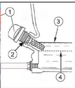
①オイルディップスティック
②オイルフィラーネック
③最大オイルレベル(MAX)
④最低オイルレベル(MIN)
①燃料コック
②0リング
③セジメントカップ
①スパークプラグ用レンチ
ボンネットを取り外した状態
①サイドブラシ
②ネジ
natural_image
3D mechanical component with a yellow brush head and labeled parts (1, 2, 3), showing internal structure and assembly details (no text or symbols beyond labels)①ローラーブラシ
②スイープローラーマウント
③進行方向前方への毛先のアラインメント
①固定部
②サイドシールストリップ
③フロントシールストリップ
④リアシールストリップ
①カバー
②凹型グリップ
③ダストフィルターのレバー
④ダストフィルター(円形フィルター)
- ボルトを取り付けます。
natural_image
Close-up of a cleaning or cleaning machine with a red arrow pointing to the component, showing no visible text or symbols.
Chairman of the Board of Management

S. Reiser
Director Regulatory Affairs & Certification
文書の全権委員:
S. Reiser
Alfred Kärcher SE & Co. KG
Alfred-Kärcher-Str. 28 - 40
71364 Winnenden (Germany)
電話番号:+49 7195 14-0
natural_image
Black silhouette of a hand giving a thumbs-up gesture (no text or symbols)THANK YOU!
MERCI! DANKE! iGRACIAS!
Registrieren Sie Ihr Produkt und profitieren Sie von vielen Vorteilen. Register your product and benefit from many advantages. Enregistrez votre produit et bénéficier de nombreux avantages. Registre su producto y aproveche de muchas ventajas.
www.kaercher.com/welcome

Bewerten Sie Ihr Produkt und sagen Sie uns Ihre Meinung. Rate your product and tell us your opinion. Évaluer votre produit et dites-nous votre opinion. Reseñe su producto y díganos su opinión.

natural_image
Icon showing a gear and wrench, no text or symbols presentwww.kaercher.com/dealersearch
Alfred Kärcher SE & Co. KG
Alfred-Kärcher-Str. 28-40
71364 Winnenden (Germany)