
CL18DA - Electric stapler HiKOKI - Free user manual and instructions
Find the device manual for free CL18DA HiKOKI in PDF.

| Product type | Cordless threaded rod cutter |
| Brand | HiKOKI |
| Model | CL18DA |
| Power source | 18 V Li-ion battery (multi-voltage 18/36 V) |
| Cutting capacity (mild steel) | M6, M8, M10, M12, W5/16, W3/8, W1/2 |
| Cutting capacity (stainless steel) | W3/8 |
| No-load stroke | 28 min⁻¹ |
| Weight (depending on battery) | 3.1 to 3.6 kg |
| Sound pressure level | 70 dB(A) (uncertainty K=1.5 dB) |
| Sound power level | 78 dB(A) (uncertainty K=1.5 dB) |
| Vibration (rod cutting) | < 0.8 m/s² (K=1.5 m/s²) |
| Main functions | Automatic stop, forward/reverse, LED lighting, battery indicator, hook, collection tray, graduation scale, integrated deburrer |
| Safety | Switch lock, overload and overheat protection, emergency stop in reverse |
| Maintenance and cleaning | Regularly clean chips around the cutter, check screws, wipe with a dry cloth, store below 40°C |
| Spare parts and repairability | Interchangeable cutters (4 edges), spacers, deburrer, hex key; repair by HiKOKI authorized service |
| Included accessories | Cutters (M6, M8, M10, W3/8), spacers, deburrer, hex key, scale, tray, shoulder strap, stackable case |
| Warranty | Complies with national regulations; excludes defects from misuse or normal wear |
Frequently Asked Questions - CL18DA HiKOKI
User questions about CL18DA HiKOKI
0 question about this device. Answer the ones you know or ask your own.
Ask a new question about this device
Download the instructions for your Electric stapler in PDF format for free! Find your manual CL18DA - HiKOKI and take your electronic device back in hand. On this page are published all the documents necessary for the use of your device. CL18DA by HiKOKI.
USER MANUAL CL18DA HiKOKI
natural_image
Technical line drawing of a mechanical device with articulated arms and control buttons (no text or symbols)
en Handling instructions
de Bedienungsanleitung
fr Mode d'emploi
it Istruzioni per l'uso
nl Gebruiksaanwijzing
es Instrucciones de manejo
pt Instruções de uso
sv Bruksanvisning
da Brugsanvisning
no Bruksanvisning
fi Käyttöohjeet
el Οδηγίες χειρισμού
pl Instrukcja obsługi
hu Kezelési utasítás
cs Návod k obsluze
tr Kullanım talimatları
ro Instructiuni de utilizare
sl Navodila za rokovanje
sk Pokyny na manipuláciu
bg Инструкция за експлоатация
sr Uputstvo za rukovanje
hr Upute za rukovanje
1
natural_image
Diagram of a hand inserting a device into a device casing, showing internal components and directional arrow (no text or symbols)2
3
4
5
natural_image
Mechanical component diagram showing two connected parts with arrows indicating direction of movement (no text or symbols)(a)(b)
natural_image
Mechanical component diagram showing a bolted joint with two threaded holes and directional arrows indicating assembly (no text or symbols)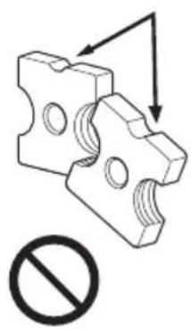
natural_image
Mechanical component diagram showing a gear-like structure with a circular end and a downward arrow, alongside a prohibition symbol (no text or labels)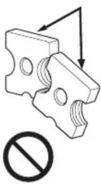
natural_image
Mechanical component diagram with no text or symbols, showing a gear-like structure and a prohibition symbol (no text or labels)6
7
8
9
10
11
12
13
natural_image
Line drawing of a person using a handheld device to stop a circular object (no text or symbols present)14
15
natural_image
Technical line drawing of a mechanical device with labeled component '24' (no text or symbols beyond label)16
natural_image
Two mechanical components with threaded ends and holes, no text or symbols visible[1]
[2]
[3]
[4]
17
18
19
20
21
22
natural_image
Mechanical component diagram showing a lever mechanism with arrows indicating motion and part number 39 (no text or symbols present)23
24
natural_image
Pure mechanical diagram showing a curved component with a labeled dimension (46), no text or symbols present.25
26
27
28
| AttachmentSize | ||
| W1/2 | 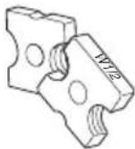 | 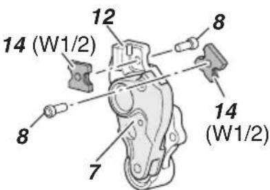 |
| W3/8M12 | 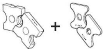 | 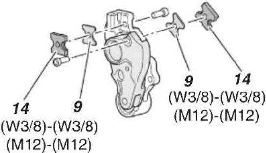 |
| W5/16M10M8M6 | 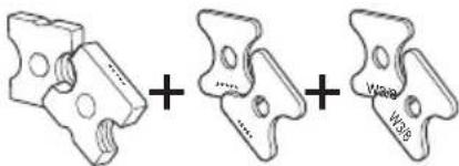 | 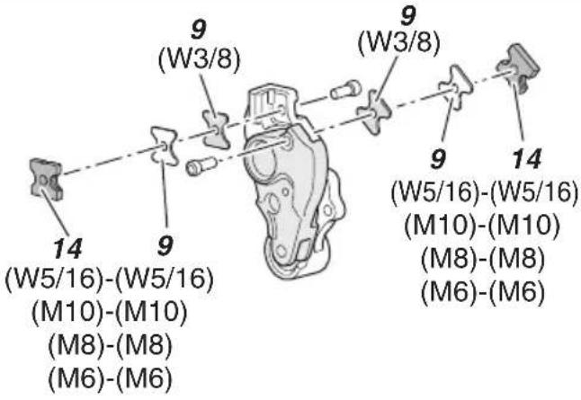 |
29
30
31
GENERAL POWER TOOL SAFETY WARNINGS
WARNING
Read all safety warnings, instructions, illustrations and specifications provided with this power tool.
Failure to follow all instructions listed below may result in electric shock, fire and/or serious injury.
Save all warnings and instructions for future reference.
The term “power tool” in the warnings refers to your mains-operated (corded) power tool or battery-operated (cordless) power tool.
1) Work area safety
a) Keep work area clean and well lit.
Cluttered or dark areas invite accidents.
b) Do not operate power tools in explosive atmospheres, such as in the presence of flammable liquids, gases or dust.
Power tools create sparks which may ignite the dust or fumes.
c) Keep children and bystanders away while operating a power tool.
Distractions can cause you to lose control.
2) Electrical safety
a) Power tool plugs must match the outlet. Never modify the plug in any way. Do not use any adapter plugs with earthed (grounded) power tools.
Unmodified plugs and matching outlets will reduce risk of electric shock.
b) Avoid body contact with earthed or grounded surfaces, such as pipes, radiators, ranges and refrigerators.
There is an increased risk of electric shock if your body is earthed or grounded.
c) Do not expose power tools to rain or wet conditions.
Water entering a power tool will increase the risk of electric shock.
d) Do not abuse the cord. Never use the cord for carrying, pulling or unplugging the power tool. Keep cord away from heat, oil, sharp edges or moving parts.
Damaged or entangled cords increase the risk of electric shock.
e) When operating a power tool outdoors, use an extension cord suitable for outdoor use.
Use of a cord suitable for outdoor use reduces the risk of electric shock.
f) If operating a power tool in a damp location is unavoidable, use a residual current device (RCD) protected supply.
Use of an RCD reduces the risk of electric shock.
3) Personal safety
a) Stay alert, watch what you are doing and use common sense when operating a power tool. Do not use a power tool while you are tired or under the influence of drugs, alcohol or medication.
A moment of inattention while operating power tools may result in serious personal injury.
b) Use personal protective equipment. Always wear eye protection.
Protective equipment such as a dust mask, non-skid safety shoes, hard hat or hearing protection used for appropriate conditions will reduce personal injuries.
c) Prevent unintentional starting. Ensure the switch is in the off-position before connecting to power source and/or battery pack, picking up or carrying the tool. Carrying power tools with your finger on the switch or energising power tools that have the switch on invites accidents.
d) Remove any adjusting key or wrench before turning the power tool on.
A wrench or a key left attached to a rotating part of the power tool may result in personal injury.
e) Do not overreach. Keep proper footing and balance at all times.
This enables better control of the power tool in unexpected situations.
f) Dress properly. Do not wear loose clothing or jewellery. Keep your hair and clothing away from moving parts.
Loose clothes, jewellery or long hair can be caught in moving parts.
g) If devices are provided for the connection of dust extraction and collection facilities, ensure these are connected and properly used.
Use of dust collection can reduce dust-related hazards.
h) Do not let familiarity gained from frequent use of tools allow you to become complacent and ignore tool safety principles.
A careless action can cause severe injury within a fraction of a second.
4) Power tool use and care
a) Do not force the power tool. Use the correct power tool for your application.
The correct power tool will do the job better and safer at the rate for which it was designed.
b) Do not use the power tool if the switch does not turn it on and off.
Any power tool that cannot be controlled with the switch is dangerous and must be repaired.
c) Disconnect the plug from the power source and/or remove the battery pack, if detachable, from the power tool before making any adjustments, changing accessories, or storing power tools.
Such preventive safety measures reduce the risk of starting the power tool accidentally.
d) Store idle power tools out of the reach of children and do not allow persons unfamiliar with the power tool or these instructions to operate the power tool.
Power tools are dangerous in the hands of untrained users.
e) Maintain power tools and accessories. Check for misalignment or binding of moving parts, breakage of parts and any other condition that may affect the power tool's operation. If damaged, have the power tool repaired before use.
Many accidents are caused by poorly maintained power tools.
f) Keep cutting tools sharp and clean.
Properly maintained cutting tools with sharp cutting edges are less likely to bind and are easier to control.
g) Use the power tool, accessories and tool bits etc. in accordance with these instructions, taking into account the working conditions and the work to be performed.
Use of the power tool for operations different from those intended could result in a hazardous situation.
h) Keep handles and grasping surfaces dry, clean and free from oil and grease.
Slippery handles and grasping surfaces do not allow for safe handling and control of the tool in unexpected situations.
5) Battery tool use and care
a) Recharge only with the charger specified by the manufacturer.
A charger that is suitable for one type of battery pack may create a risk of fire when used with another battery pack.
b) Use power tools only with specifically designated battery packs.
Use of any other battery packs may create a risk of injury and fire.
c) When battery pack is not in use, keep it away from other metal objects, like paper clips, coins, keys, nails, screws or other small metal objects, that can make a connection from one terminal to another.
Shorting the battery terminals together may cause burns or a fire.
d) Under abusive conditions, liquid may be ejected from the battery; avoid contact. If contact accidentally occurs, flush with water. If liquid contacts eyes, additionally seek medical help.
Liquid ejected from the battery may cause irritation or burns.
e) Do not use a battery pack or tool that is damaged or modified.
Damaged or modified batteries may exhibit unpredictable behaviour resulting in fire, explosion or risk of injury.
f) Do not expose a battery pack or tool to fire or excessive temperature.
Exposure to fire or temperature above 130^ C may cause explosion.
g) Follow all charging instructions and do not charge the battery pack or tool outside the temperature range specified in the instructions.
Charging improperly or at temperatures outside the specified range may damage the battery and increase the risk of fire.
6) Service
a) Have your power tool serviced by a qualified repair person using only identical replacement parts.
This will ensure that the safety of the power tool is maintained.
b) Never service damaged battery packs.
Service of battery packs should only be performed by the manufacturer or authorized service providers.
PRECAUTION
Keep children and infirm persons away.
When not in use, tools should be stored out of reach of children and infirm persons.
PRECAUTIONS FOR CORDLESS STUD CUTTER
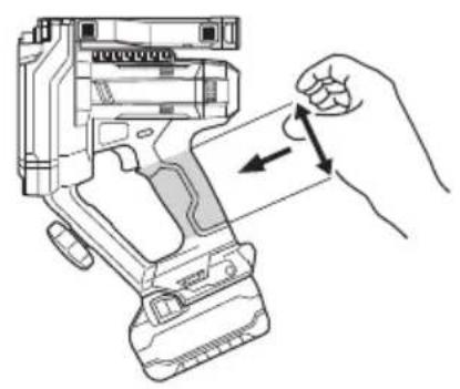
- Make sure to securely hold the tool during operation.
Failure to do so can result in accidents or injuries. (Fig. 1)
-
Never bring the cutter near your fingers when operating the switch.
-
Do not use for cutting studs other than soft steel studs. This tool is designed especially for cutting of soft steel studs. Using this tool for studs that are not according to specifications could cause distortions in the screw
threads, thereby preventing insertion of nuts.
Never use to cut tempered bolts, studs of differing sizes, reinforcing rods, etc.
-
Use by changing the special cutters according to the size of the studs. Cutting with cutters of the wrong size could damage to the continuous thread studs or the cutter edges.
-
Make sure that the threads on the studs and those on the cutter are correctly meshed before starting to cut. Cutting when the threads are not meshed could cause damage to the studs and the cutter.
-
If the cutter has been attached in the wrong direction or the bolt for cutter attachment is loose, this could cause damage to the cutter edge and could lead to premature damage to the main unit.
Be very careful to attach the cutter correctly.
-
Cutting studs at short lengths of 10 millimeters or less will create an insufficient meshing length between the cutter and studs, thus causing damage to the cutter. Always cut at lengths of more than 10 millimeters.
-
When cutting studs secured to narrow locations, be sure that there is at least 12 millimeters between the stud and the surrounding materials.
If the distance is less than 12 millimeters the cutter could contact the surrounding materials, thereby causing damage to the cutter and the main unit.
-
When inspecting, cleaning or replacing the cutter, be sure to remove the battery from the main unit. The switch could be turned on accidentally, thereby causing accidents.
-
When using this equipment at heights, make doubly sure prior to use that there is no one standing in the area immediately below you. Place the tool in a safe and stable place when not using at the moment.
-
Always charge the battery at a temperature of 0^ C– 40^ C. A temperature of less than 0^ C will result in over charging which is dangerous. The battery cannot be charged at a temperature higher than 40^ C. The most suitable temperature for charging is that of 20^ C– 25^ C.
-
Do not use the charger continuously. When one charging is completed, leave the charger for about 15 minutes before the next charging of battery.
-
Do not allow foreign matter to enter the hole for connecting the rechargeable battery.
-
Never disassemble the rechargeable battery and charger.
-
Never short-circuit the rechargeable battery. Short-circuiting the battery will cause a great electric current and overheat. It results in burn or damage to the battery.
-
Do not dispose of the battery in fire. If the battery is burnt, it may explode.
-
Do not insert objects into the air ventilation slots of the charger. Inserting metal objects or inflammables into the charger air ventilation slots will result in electrical shock hazard or a damaged charger.
-
Bring the battery to the shop from which it was purchased as soon as the post-charging battery life becomes too short for practical use. Do not dispose of the exhausted battery.
-
Using an exhausted battery will damage the charger.
-
When using this unit continuously, the unit may overheat, leading to damage in the motor and switch. Therefore, whenever the housing becomes hot, give the tool a break for a while.
-
Make sure that the battery is installed firmly. If it is at all loose it could come off and cause an accident.
-
Do not use the product if the tool or the battery terminals (battery mount) are deformed. Installing the battery could cause a short circuit that could result in smoke emission or ignition.
English
- Keep the tool's terminals (battery mount) free of swarf and dust.
- Prior to use, make sure that swarf and dust have not collected in the area of the terminals.
○ During use, try to avoid swarf or dust on the tool from falling on the battery.
○ When suspending operation or after use, do not leave the tool in an area where it may be exposed to falling swarf or dust.
Doing so could cause a short circuit that could result in smoke emission or ignition.
- Always use the tool and battery at temperatures between -5^ and 40^ .
CAUTION ON LITHIUM-ION BATTERY
To extend the lifetime, the lithium-ion battery equips with the protection function to stop the output.
In the cases of 1 to 3 described below, when using this product, even if you are pulling the switch, the motor may stop. This is not the trouble but the result of protection function.
- When the battery power remaining runs out, the motor stops. In such a case, charge it up immediately.
- If the tool is overloaded, the motor may stop. In this case, release the switch of tool and eliminate causes of overloading. After that, you can use it again.
- If the battery is overheated under overload work, the battery power may stop. In this case, stop using the battery and let the battery cool. After that, you can use it again.
Furthermore, please heed the following warning and caution.
WARNING
In order to prevent any battery leakage, heat generation, smoke emission, explosion and ignition beforehand, please be sure to heed the following precautions.
- Make sure that swarf and dust do not collect on the battery.
○ During work make sure that swarf and dust do not fall on the battery.
○ Make sure that any swarf and dust falling on the power tool during work do not collect on the battery.
○ Do not store an unused battery in a location exposed to swarf and dust.
Before storing a battery, remove any swarf and dust that may adhere to it and do not store it together with metal parts (screws, nails, etc.). - Do not pierce battery with a sharp object such as a nail, strike with a hammer, step on, throw or subject the battery to severe physical shock.
- Do not use an apparently damaged or deformed battery.
- Do not use the battery for a purpose other than those specified.
- If the battery charging fails to complete even when a specified recharging time has elapsed, immediately stop further recharging.
- Do not put or subject the battery to high temperatures or high pressure such as into a microwave oven, dryer, or high pressure container.
- Keep away from fire immediately when leakage or foul odor are detected.
- Do not use in a location where strong static electricity generates.
-
If there is battery leakage, foul odor, heat generated, discolored or deformed, or in any way appears abnormal during use, recharging or storage, immediately remove it from the equipment or battery charger, and stop use.
-
Do not immerse the battery or allow any fluids to flow inside. Conductive liquid ingress, such as water, can cause damage resulting in fire or explosion. Store your battery in a cool, dry place, away from combustible and flammable items. Corrosive gas atmospheres must be avoided.
- Do not give a strong shock to the display panel or break it. It may lead to a trouble.
- If alkaline lubricant or cutting fluid adheres to the battery, quickly wipe it off with a dry cloth. Failure to do so may result in damage or degradation of the case.
CAUTION
- If liquid leaking from the battery gets into your eyes, do not rub your eyes and wash them well with fresh clean water such as tap water and contact a doctor immediately.
If left untreated, the liquid may cause eye-problems.
- If liquid leaks onto your skin or clothes, wash well with clean water such as tap water immediately.
There is a possibility that this can cause skin irritation. - If you find rust, foul odor, overheating, discolor, deformation, and/or other irregularities when using the battery for the first time, do not use and return it to your supplier or vendor.
WARNING
If a conductive foreign matter enters in the terminal of lithium ion battery, the battery may be shorted, causing fire. When storing the lithium ion battery, obey surely the rules of following contents.
○ Do not place conductive debris, nail and wires such as iron wire and copper wire in the storage case.
To prevent shorting from occurring, load the battery in the tool or insert securely the battery cover for storing until the ventilator is not seen.
REGARDING LITHIUM-ION BATTERY TRANSPORTATION
When transporting a lithium-ion battery, please observe the following precautions.
WARNING
Notify the transporting company that a package contains a lithium-ion battery, inform the company of its power output and follow the instructions of the transportation company when arranging transport.
○ Lithium-ion batteries that exceed a power output of 100 Wh are considered to be in the freight classification of Dangerous Goods and will require special application procedures.
○ For transportation abroad, you must comply with international law and the rules and regulations of the destination country.
Power Output

2 to 3 digit number
natural_image
Simple line drawing of a rectangular device with a central screen and side connectors (no text or symbols)USB DEVICE CONNECTION PRECAUTIONS (UC18YSL3)
When an unexpected problem occurs, the data in a USB device connected to this product may be corrupted or lost. Always make sure to back up any data contained in the USB device prior to use with this product.
Please be aware that our company accepts absolutely no responsibility for any data stored in a USB device that is corrupted or lost, nor for any damage that may occur to a connected device.
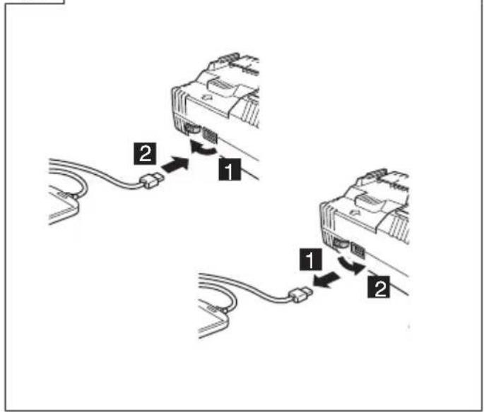
WARNING
- Prior to use, check the connecting USB cable for any defect or damage.
Using a defective or damaged USB cable can cause smoke emission or ignition.
○ When the product is not being used, cover the USB port with the rubber cover.
Buildup of dust etc. in the USB port can cause smoke emission or ignition.
NOTE
- There may be an occasional pause during USB recharging.
When a USB device is not being charged, remove the USB device from the charger. Failure to do so may not only reduce the battery life of a USB device, but may also result in unexpected accidents.
○ It may not be possible to charge some USB devices, depending on the type of device.
NAMES OF PARTS
The numbers in the list below correspond to Fig. 1–Fig. 31.
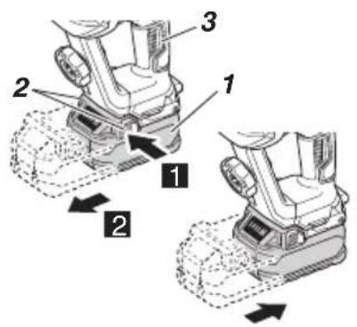
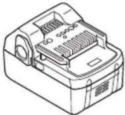
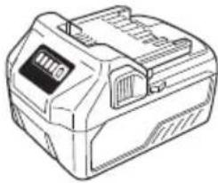
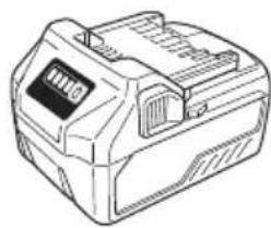
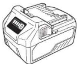
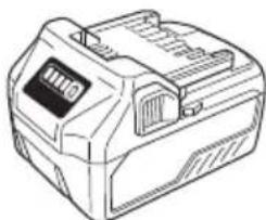
| 1 | Rechargeable battery |
| 2 | Latch (For battery) |
| 3 | Handle |
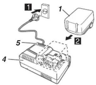
| 4 | Charger |
| 5 | Charge indicator lamp |
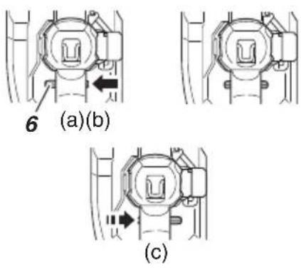
| 6 | Forward/Reverse switching button |
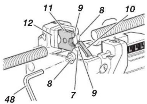
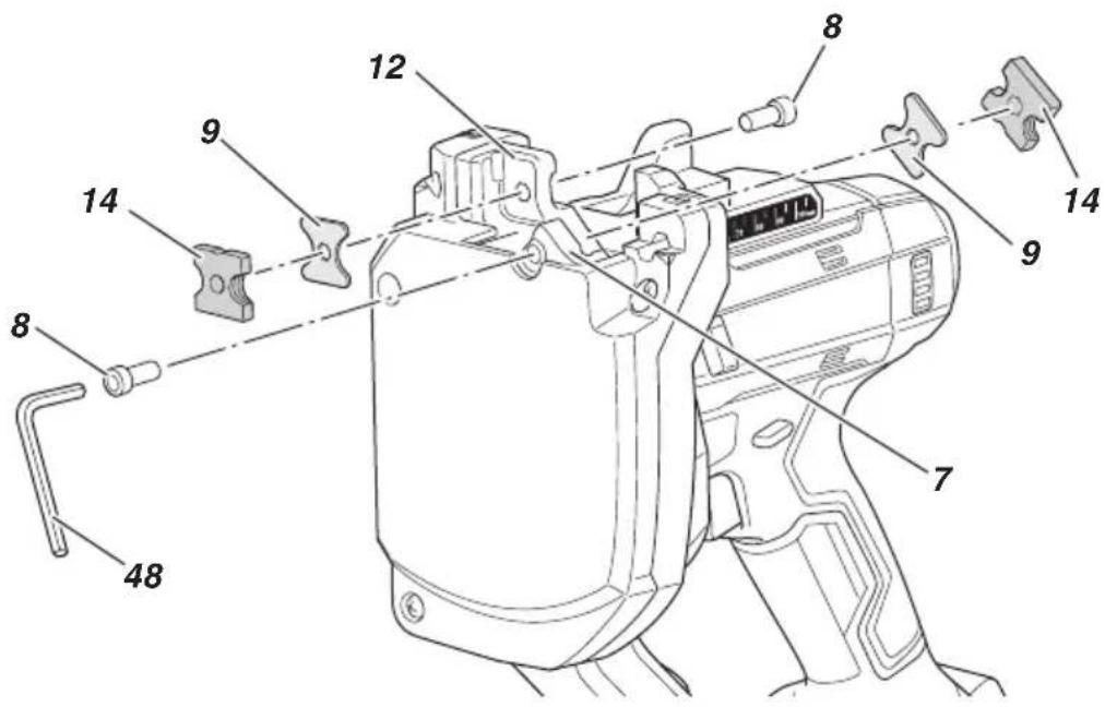
| 7 | Bracket (A) (movable side) |
| 8 | Hex. Socket hd.bolt |
| 9 | Spacer (used only with M6, M8, M10, M12, W5/16, W3/8) |
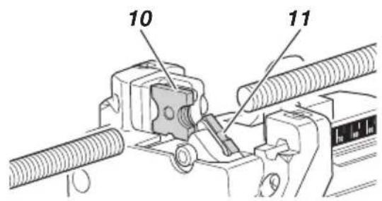
| 10 | Side without notch |
| 11 | Notch side |
| 12 | Bracket (B) (fixed side) |
| 13 | Stud |
| 14 | Cutter |
| 15 | Correctly mesh |
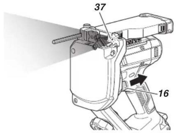
| 16 | Trigger switch |
| 17 | Foot surface |
| 18 | Stud suspended from the ceiling |
| 19 | Ceiling |
| 20 | Scale |
| 21 | Cover |
| 22 | Hook |
| 23 | Latch (For hook) |
| 24 | Trimmer |
| 25 | Pliers |
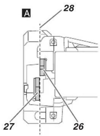
| 26 | Fixed cutter |
| 27 | Movable cutter |
| 28 | Cutting position |
| 29 | Necessary length |
| 30 | Knob bolt |
| 31 | Tighten |
| 32 | Loosen |
| 33 | Measurement position |
| 34 | Hole (For knob bolt) |
| 35 | Length (cutting position-Scale (Main body)) = 43 [mm] |
| 36 | Scale (Main body) |
| 37 | LED light |
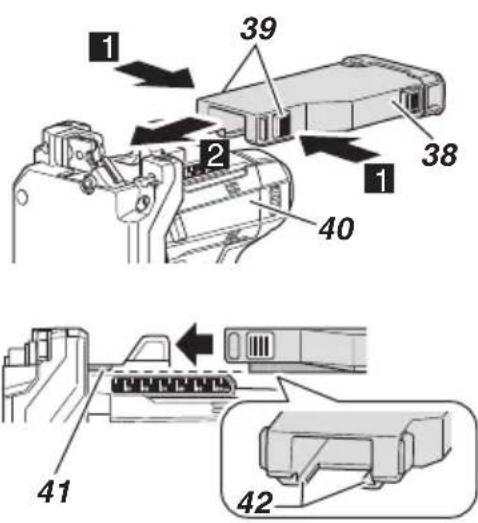
| 38 | Collection box |
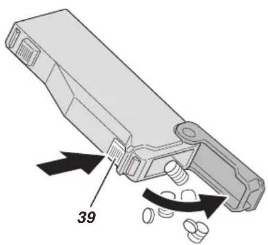
| 39 | Latch (For collection box) |
| 40 | Housing |
| 41 | Slider (Housing) |
| 42 | Slider (Collection box) |
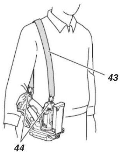
| 43 | Shoulder strap |
| 44 | Hook (A) |
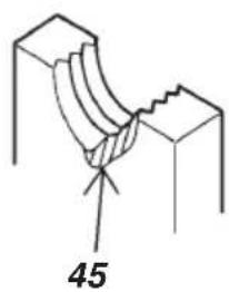
| 45 | Breaking |
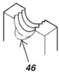
| 46 | Warping |
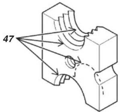
| 47 | Four edges on the cutter |
| 48 | Hex. bar wrench |
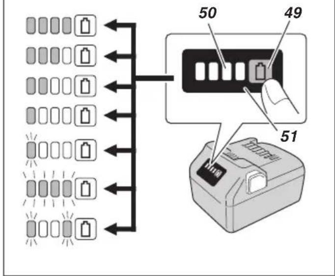
| 49 | Remaining battery indicator switch |
| 50 | Remaining battery indicator lamp |
| 51 | Display panel |
SYMBOLS
WARNING
The following show symbols used for the machine. Be sure that you understand their meaning before use.


CL18DA: Cordless Stud Cutter
To reduce the risk of injury, user must read instruction manual.
English
 | Only for EU countriesDo not dispose of electric tools together with household waste material!In observance of European Directive 2012/19/EU on waste electrical and electronic equipment and its implementation in accordance with national law, electric tools that have reached the end of their life must be collected separately and returned to an environmentally compatible recycling facility. |
| Direct current | |
| V | Rated voltage |
| n_0 | No-load speed |
 | Disconnect the battery |
 | Warning |
 | Prohibited action |
SPECIFICATIONS
- Power tool
| Model CL18DA | ||
| No-load stroke 28 min | -1 | |
| Capacity | Soft steel studs | M12, M10, M8, M6, W1/2, W3/8, W5/16 |
| Stainless steel studs | W3/8 | |
| Rechargeable battery BSL1815-BSL36B18X | ||
| Weight*1 | 3.1–3.6 kg | |
*1 Weight: According to EPTA-Procedure 01/2014 Depending on attached battery. The heaviest weight is measured with BSL36B18X.
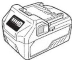
- Battery (sold separately)
| Model Voltage Battery capacity | ||
| BSL36A18X 36 | / 18 V *1 | 2.5 / 5.0 Ah *1 |
*1 The tool itself will automatically switch over.
STANDARD ACCESSORIES
| CL18DA | |
| NNP | |
| M6 Cutter 2 | |
| M6 Spacer 2 | |
| M8 Cutter 2 | |
| M8 Spacer 2 | |
| M10 Cutter 2 |
| M10 Spacer 2 | |
| W3/8 Spacer 2 | |
| M8 Trimmer 1 | |
| Hex. Bar wrench 1 | |
| Scale 1 | |
| Collection box 1 | |
| Stackable case 1 | |
| Shoulder strap 1 |
Standard accessories are subject to change without notice.
OPTIONAL ACCESSORIES (sold separately)
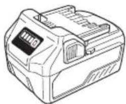
- Battery
natural_image
Line drawing of a mechanical device with no visible text or symbols(BSL1830, BSL1840, BSL1850, BSL1860)
natural_image
Line drawing of a portable electronic device with control panel and display (no text or symbols)(BSL36..18)
- Cutter
| Stud size | Combination cutters and spacers | |
| M12 | M12 Cutter (×2)M12 Spacer (×2) |  |
| M10 | M10 Cutter (×2)M10 Spacer (×2) | |
| M8 | M8 Cutter (×2)M8 Spacer (×2) | |
| M6 | M6 Cutter (×2)M6 Spacer (×2) | |
| W1/2 | W1/2 Cutter (×2) | 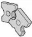 |
| W3/8 | W3/8 Cutter (×2)W3/8 Spacer (×2) |  |
| W5/16 | W5/16 Cutter (×2)W5/16 Spacer (×2) | |
- Trimmer
| Stud size | 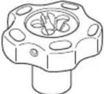 |
| M12 | |
| M10 | |
| M8 | |
| M6 | |
| W1/2 | |
| W3/8 | |
| W5/16 |
4. Shoulder strap
By attaching the shoulder-hanging strap to the hook (A) that is included with this product, you can carry the product as shown in the Fig. 23.
CAUTION
○ Adjust the shoulder strap to an appropriate length before using it.
○ Do not use the shoulder strap if it is damaged.
Optional accessories are subject to change without notice.
APPLICATIONS
○ Cutting of soft steel studs.
BATTERY REMOVAL/INSTALLATION
1. Battery removal
Hold the handle tightly and push the battery latch to remove the battery (see Fig. 2)
CAUTION
Never short-circuit the battery.
2. Battery installation
Insert the battery while observing its polarities (see Fig. 2).
CHARGING
Before using the power tool, charge the battery as follows.
1. Connect the charger's power cord to the receptacle.
When connecting the plug of the charger to a receptacle, the charge indicator lamp will blink in red. (See Table 1)
2. Insert the battery into the charger.
Firmly insert the battery into the charger as shown in Fig. 3 (on page 2).
3. Charging
When inserting a battery in the charger, charging will commence and the charge indicator lamp will blink in blue.
When the battery becomes fully recharged, the charge indicator lamp will light up in green. (See Table 1)
(1) Charge indicator lamp indication
The indications of the charge indicator lamp will be as shown in Table 1, according to the condition of the charger or the rechargeable battery.
Table 1: Indications of the charge indicator lamp
| ON/OFF at 0.5 sec. intervals (RED) | Before charging *1 |
| Lights for 0.5 sec. at intervals of 1 sec. (BLUE) | Charged at less than 50% |
| Lights for 1 sec. at intervals of 0.5 sec. (BLUE) | Charged at less than 80% |
| Lights continuously (BLUE) | Charged at more than 80% |
| Lights continuously (Continuous buzzer sound: about 6 sec.) (GREEN) | Charging complete |
| ON/OFF at 0.3 sec. intervals (RED) | Overheat standby *2 |
| ON/OFF at 0.1 sec. intervals (Intermittent buzzer sound: about 2 sec.) (PURPLE) | Charging impossible *3 |
NOTE
*1 If the red lamp continues to blink even after the charger has been attached, check to confirm that the battery has been fully inserted.
*2 Battery overheated. Unable to charge.
Although charging will start once the battery has cooled down even when left in situ, the best practice is to remove the battery and allow it to cool down in a shaded, well-ventilated location before charging.
*3 Malfunction in the battery or the charger – Fully insert the battery.
- Check to confirm that no foreign matter is stuck to the battery mount or terminals. If there are no foreign objects, it is probable that the battery or charger is malfunctioning. Take it to your authorized Service Center.
When the battery charger has been continuously used, the battery charger will be heated, thus constituting the cause of the failures. Once the charging has been completed, give 5 minutes rest until the next charging.
(2) Regarding the temperatures and charging time of the battery (See Table 2)
Table 2
| Model UC18YSL3 | ||
| Type of battery Li-ion | ||
| Charging voltage 14.4–18 V | ||
| Temperatures at which the battery can be recharged | 0°C–50°C | |
| Charging time for battery capacity, approx. (At 20°C) | 1.5 Ah 15 | min |
| 2.0 Ah 20 | min | |
| 2.5 Ah 25 | min | |
English
| Charging time for battery capacity, approx. (At 20°C) | 3.0 Ah | 20 min(BSL1430C, BSL1830C: 30 min) |
| 4.0 Ah | 26 min(BSL1840M: 40 min) | |
| 5.0 Ah 32 | min | |
| 6.0 Ah 38 | min | |
| Charging time for multi volt battery capacity, approx. (At 20°C) | 1.5 Ah(× 2 unit) | 20 min |
| 2.5 Ah(× 2 unit) | 32 min | |
| 4.0 Ah(× 2 unit) | 52 min | |
| Number of battery cells 4–10 | ||
| Charging voltage for USB 5 V | ||
| Charging current for USB 2 A | ||
| Weight 0.6 kg | ||
NOTE
-
The recharging time may vary according to the ambient temperature and power source voltage.
○ If charging takes a long time -
Charging will take longer at extremely low ambient temperatures. Charge the battery in a warm location (such as indoors).
- Do not block the air vent. Otherwise the interior will overheat, reducing the charger's performance.
-
If the cooling fan is not operating, contact a HiKOKI Authorized Service Center for repairs.
-
Disconnect the charger's power cord from the receptacle.
-
Hold the charger firmly and pull out the battery. NOTE
Be sure to pull out the battery from the charger after use, and then keep it.
Regarding electric discharge in case of new batteries, etc.
As the internal chemical substance of new batteries and batteries that have not been used for an extended period is not activated, the electric discharge might be low when using them the first and second time. This is a temporary phenomenon, and normal time required for recharging will be restored by recharging the batteries 2–3 times.
How to make the batteries perform longer.
(1) Recharge the batteries before they become completely exhausted. When you feel that the power of the tool becomes weaker, stop using the tool and recharge its battery. If you continue to use the tool and exhaust the electric current, the battery may be damaged and its life will become shorter.
(2) Avoid recharging at high temperatures. A rechargeable battery will be hot immediately after use. If such a battery is recharged immediately after use, its internal chemical substance will deteriorate, and the battery life will be shortened. Leave the battery and recharge it after it has cooled for a while.
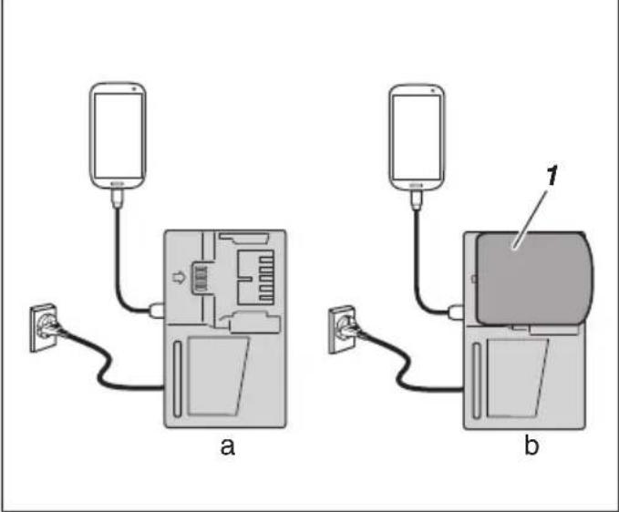
HOW TO RECHARGE USB DEVICE
○ Charging a USB device from an electrical outlet (Fig. 30 (a))
○ Charging a USB device and battery from an electrical outlet (Fig. 30 (b))
O How to recharge USB device (Fig. 31)
PRIOR TO OPERATION
- Preparing and checking the work environment Make sure that the work site meets all the conditions laid forth in the precautions.
- Checking the battery
Make sure that the battery is installed firmly. If it is at all loose it could come off and cause an accident.
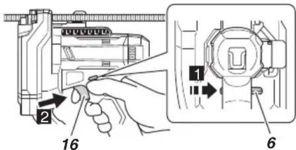
- Setting the forward/reverse switching button
(1) Push the forward/reverse switching button from the right as shown in Fig. 4 (a). Cutting is possible.
(2) By setting the forward/reverse switching button in the lock position as shown in Fig. 4 (b), the motor will not operate even if the trigger switch is pulled. When carrying or storing the main unit or when stopping operations, set the forward/reverse switching button to the lock position (Fig. 4 (b)).
(3) Push the forward/reverse switching button from the left as shown in Fig. 4 (c). With the button held down, pull the trigger switch so that the cutter can be removed from the stud. Only set to this position if the rechargeable battery is worn out and the unit stops operating during cutting. Immediately turn off the switch after the cutter has been removed from the stud.
CAUTION
Do not attempt to cut in the reverse position (Fig. 4 (c)). If you attempt to cut in this position, there will be an overload on the motor and cutting will not be possible. Never apply excessive force to the main unit as this can cause damage to the unit.
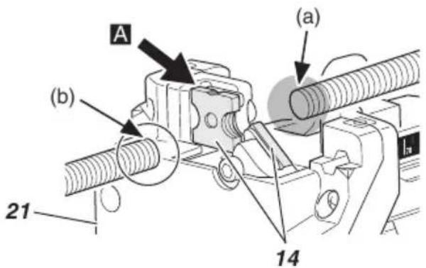
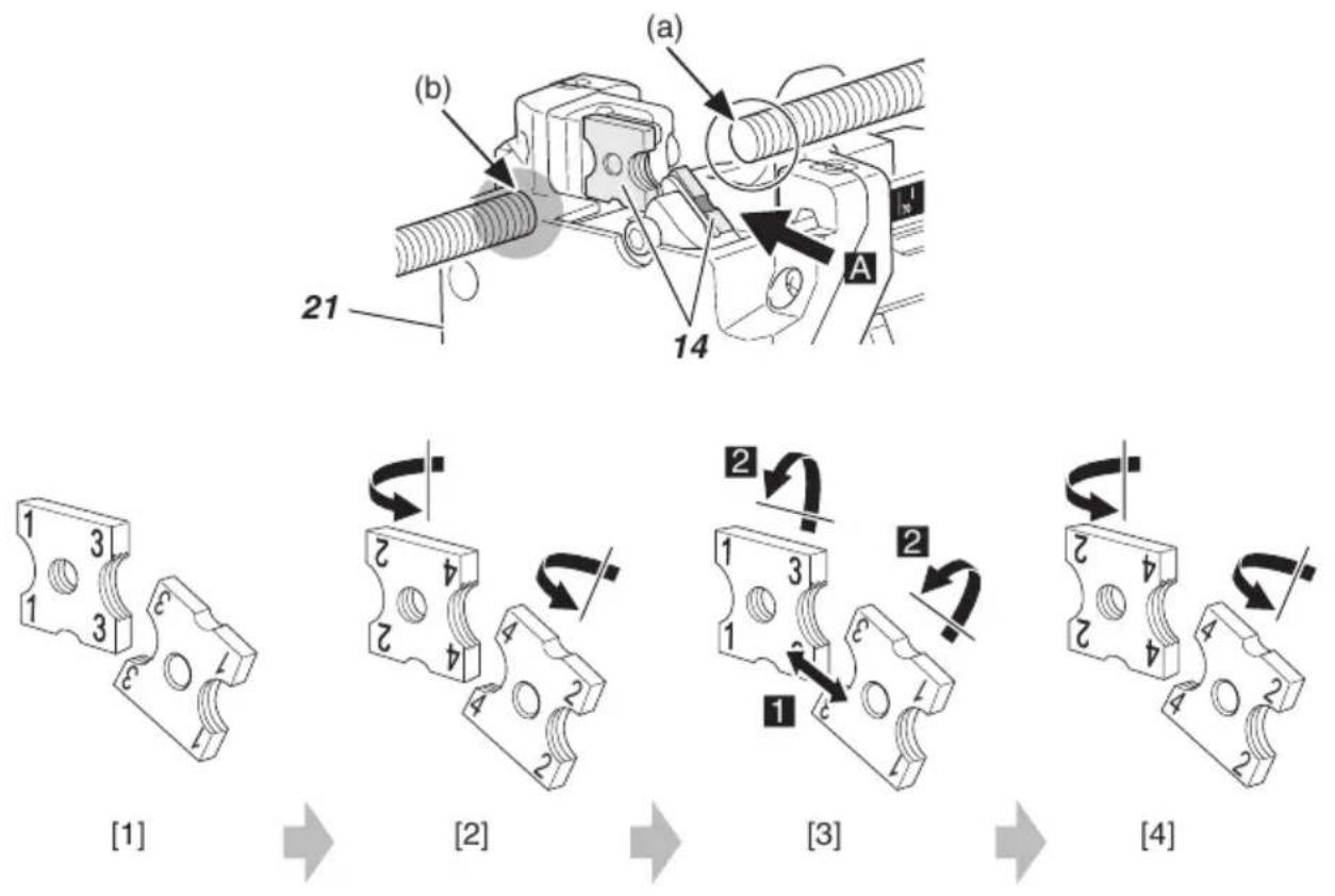
- Check the cutter size, attachment direction, attachment bolt and spacer
(1) The cutter size differs according to the size of the studs to be cut. Make sure that a cutter is attached that conforms to the size of the studs to be cut.
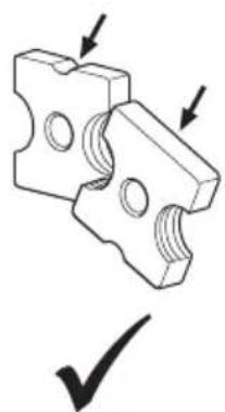
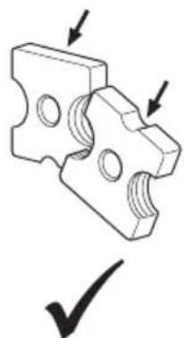
(2) When changing the installation position of the cutter, the cutters must be in the correct positions in relation to each other.
When viewing from the front (cover side) of the tool body, place the notches on the sides of the cutters so that the parts
(3) Use the accessory hex. bar wrench to insure that the hex. socket hd. bolt for attaching the cutter is securely tightened (Fig. 5). Using the equipment while the bolt is loose could cause damage to the main unit and cutter.
(4) Depending on the size of the studs it may be necessary to attach special spacers to the cutter.
[1] When using an M6, M8, M10, W5/16 cutter Insert the cutter in the cutter attachment groove on the bracket insert the special spacer and W3/8 spacer between the cutter and bracket and then use the hex. Socket hd. Bolt to tighten and secure. (Fig. 28)
[2] When using an M12, W3/8 cutter
Insert the cutter in the cutter attachment groove on the bracket insert the special spacer between the cutter and bracket and then use the hex. Socket hd. Bolt to tighten and secure. (Fig. 28)
CAUTION
As shown in Fig. 5 (b), if the cutters are combined in such a way that both side without the notch on the cutter or both notch sides are facing out, the pitch of the threads on the studs and the threads on the cutter will not be in agreement. This can cause damage to the cutter edge or cause wear to premature damage to the main unit.
NOTE
Spacers are not required when using W1/2 cutter.
For details, refer to the section on "CUTTER LIFE AND REPLACEMENT".
HOW TO USE
CAUTION
- Never bring the cutter near your fingers when operating the trigger switch.
○ After cutting, the cut section of the stud is very sharp and therefore dangerous. Be very careful when handling the stud.
1. Normal Cutting Method
(1) As shown in Fig. 6, set the stud to be cut in the cutter on the bracket (B) side, making sure that the threads correctly mesh with each other.
(2) While maintaining the stud in a horizontal position, pull the trigger switch all the way to cut the stud (Fig. 7).
(3) After cutting a stud, if the trigger switch is still being pulled, the cutter automatically stops in the fully open state. After the automatic stop, release the trigger switch.
CAUTION
When the trigger switch is pulled continuously, the cutter automatically stops in the fully-opened state. (Auto-Stop function)
If the switch is released when partway through the cutter's movement, the cutter stops in that position.
2. Number of cuttings (per battery charging)
Refer to the chart below for the number of cuttings per battery charging.
Table 3
| Stud size | Soft steel* (S235JR) | Stainless steel* (EN 1.4301) |
| W5/16 approx. 2100 — | ||
| W3/8 approx. 1400 approx. 750 | ||
| W1/2 approx. 400 — | ||
| M6 approx. 3150 — | ||
| M8 approx. 1850 — | ||
| M10 approx. 1150 — | ||
| M12 approx. 770 — |
* When using battery BSL36A18X
The number of cuttings can also vary somewhat according to the ambient temperature, characteristics of the battery and the condition of the cutter.
3. Stationary cutting work (Fig. 8)
When performing stationary cutting, place the product with its foot surfaces securely on the floor, fit the stud into the threaded part of the fixed cutter on the BRACKET (B) side, then perform the cutting.
4. Cutting studs that are already secured (Fig. 9)
When cutting a stud that is hanging down from the ceiling, insert the stud so that the peaks of its thread fit properly into the cutter on the bracket (B) side, and fully pull the trigger switch to cut the stud.
CAUTION
When cutting a stud that is hanging down, hold the part of the stud that will be cut off to prevent it from falling. Be careful of falling studs that have been cut. They create a risk of accident or injury.
○ If the scale is forcefully pushed against the ceiling, it may damage the ceiling, or deform or damage the scale.
○ Wipe off any dirt on the surface of the cover of this product using a dry cloth. If there is dirt on the cover's surface, it may transfer onto the ceiling.
○ If you do not need the scale, remove it before use.
5. Removing the stud from the unit during cutting operations
If the battery wears out during cutting operations so that the motor stops rotating, or if it is stopped by a stud seizing while cutting, pull the trigger switch while pushing the forward/reverse switching button to the reverse side. The motor will rotate in the opposite direction and it will be possible to remove the stud from the cutter (Fig. 10).
CAUTION
- Put it in the reverse position only if the remaining battery is low and the motor rotation stops while cutting a stud, or if it is stopped by a stud seizing while cutting.
○ If you remove the cutter from the stud and keep the switch pulled, the cutter automatically stops in the fully-opened state.
☐ If you try to cut a stud while in the reverse position, the motor will be overloaded and it will not cut. This also puts too much stress on the tool body and may damage it, so do not cut while in the reverse position.
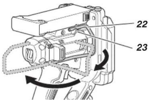
6. Using the hook
The hook can be used to hang up the unit temporarily during operations (Fig. 11).
CAUTION
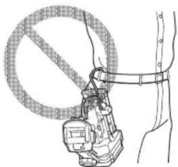
- The hook should never be used to hang the unit on your person.
When using the hook, check to make sure that the main unit will not slip and fall, or become unstable by the wind, etc.
○ Never hang the unit from your belt or trousers as this could cause accidents. (Fig. 13)
○ Do not use the hook if it is severely bent, is cracked, or has other abnormalities.
NOTE
During normal use or during storage, store the hook in the latch found on the bottom of the main unit. (Fig. 12)
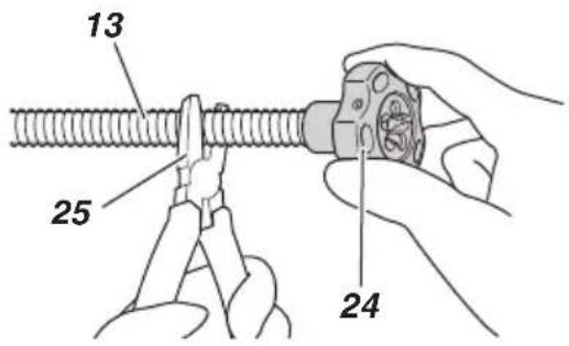
7. Using the trimmer
NOTE
Use a special trimmer that is suitable for the size of the stud.
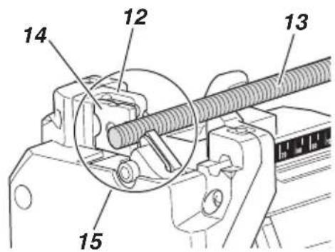
If it is difficult for the nut to enter the cutting position, either use a pliers to firmly tighten the nut or use the accessory trimmer to remove the burr on the screw thread. Insert the stud in the hole on the trimmer. Use a pliers to retain the stud and rotate the trimmer 5 or 6 times to the right to remove the burr and then rotate in the opposite direction to remove the trimmer (Fig. 14).
CAUTION
This trimmer is specially designed for Studs Cutter. The burr on studs cut with a hacksaw or disc grinder is too large for this trimmer so that the trimmer does not rotate and it is not possible to remove burr.
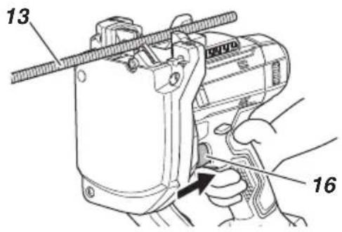
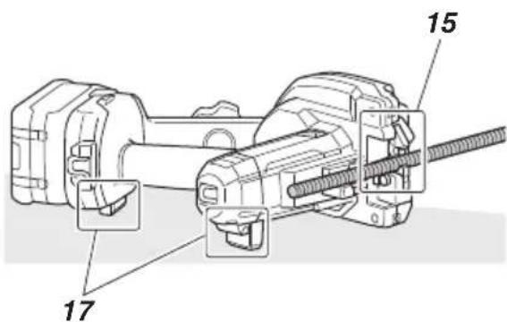
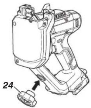
When not using the trimmer, store it in the tool body.
(Fig. 15)
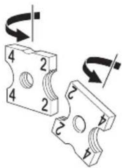
Depending on how the cutter is attached, there is a different amount of burrs around the stud cut-end after cutting.
If the cutter is attached on the attachment-point on the left side when seen from the front (cover side) so that the cutter's notch is facing up. (Fig. 16 [A])
There will be few burrs on the Fig. 16 (a) side, and many
English
burrs on the Fig. 16 (b) side. If you exchange and reattach the cutters as shown in Fig. 16 [1] to [4], it is possible to cut for long periods in the state shown in Fig. 16 (a) (b). If the cutter is attached on the attachment-point on the right side when seen from the front (cover side) so that the cutter's notch is facing up. (Fig. 17 [A]) There will be many burrs on the Fig. 17 (a) side, and few burrs on the Fig. 17 (b) side. If you exchange and reattach the cutters as shown in Fig. 17 [1] to [4], it is possible to cut for long periods in the state shown in Fig. 17 (a) (b).
CAUTION
If using a cutter that does not have numbers engraved, use the notch as a visual guide when changing the attachment orientation of the cutter. The method for changing the orientation is the same as for Fig. 16 and 17.
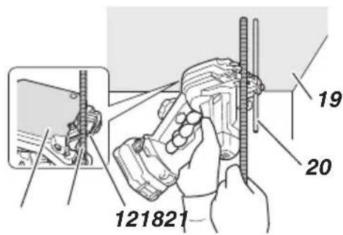
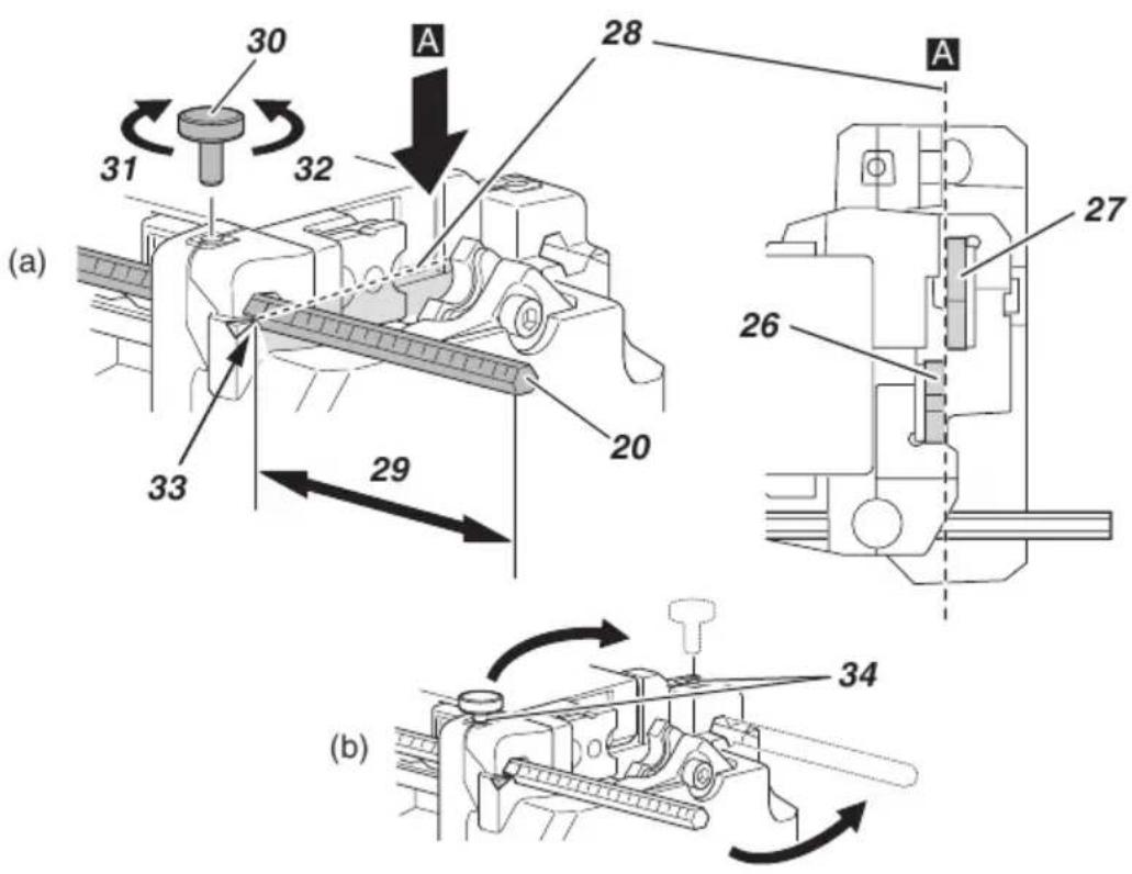
8. Using the scale
If using the included scale, after aligning to the necessary length with the scale, fix the scale in place with the knob bolt, then perform the cutting work.
(Fig. 18 (a))
It can be used in the same way on the opposite side.
(Fig. 18 (b))
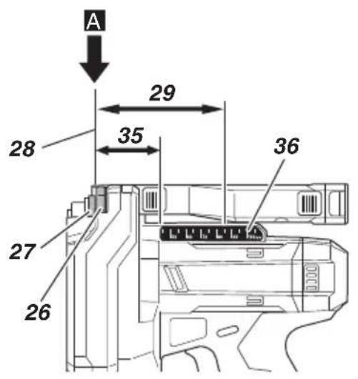
If using the main body scale, align to the necessary length with the scale affixed to the tool body, then perform the cutting work. (Fig. 19)
9. Using the LED
When the switch is pulled, the LED lights up. The LED light turns off about 10 seconds after the switch is released. (Fig. 20)
CAUTION
Do not look directly into the light or shine the light at anyone's eyes.
If the light shines into the eyes continuously, it may injure the eyes.
10. Auto-Stop function
After cutting a stud, if the switch trigger is pulled continuously, the cutter automatically stops in the fully-open state.
NOTE
○ When in reverse rotation as well, if the switch is pulled continuously, the cutter automatically stops in the fully-opened state.
○ When in reverse rotation, if the switch is pulled while the cutter is in the fully-open state, the tool does not operate.
11. Tool protection function
If you attempt to cut a material that exceeds the cutting capability such as rebar or a stud of a size not suitable for the cutter, or if working continuously and the tool body overheats, the tool protection function activates and cutting is not possible.
NOTE
○ When the tool is stopped by the protection function, the LED flashes.
○ If it is stopped by the protection function, it will operate only in the “Reverse position” direction.
12. Using the collection box
To attach the collection box, while pressing the left and right latches, align the sliders on the housing and the collection box, and then attach the collection box.
(Fig. 21)
To remove the collection box, follow the above instructions in reverse.
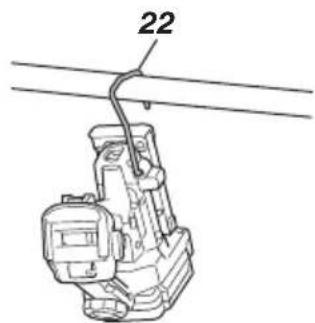
When disposing of the swarf and dust, rotate and open the lid as shown in Fig. 22.
NOTE
When cutting long studs, remove the collection box, or open its lid as shown in Fig. 22 when using it.
13. About Remaining Battery Indicator
When pressing the remaining battery indicator switch, the remaining battery indicator lamp lights and the battery remaining power can be checked. (Fig. 29) When releasing your finger from the remaining battery indicator switch, the remaining battery indicator lamp goes off. The Table 4 shows the state of remaining battery indicator lamp and the battery remaining power.
Table 4
| Lights;The battery remaining power is over 75% | |
| Lights;The battery remaining power is 50%-75%. | |
| Lights;The battery remaining power is 25%-50%. | |
| Lights;The battery remaining power is less than 25%. | |
 | Blinks;The battery remaining power is nearly empty.Recharge the battery soonest possible. |
 | Blinks;Output suspended due to high temperature.Remove the battery from the tool and allow it to fully cool down. |
 | Blinks;Output suspended due to failure or malfunction.The problem may be the battery so please contact your dealer. |
NOTE
○ When using a Multi-volt battery, please refer to the indicator lamp on the battery for the battery remaining power.
○ Do not give a strong shock to the switch panel or break it. It may lead to a trouble.
To save the battery power consumption, the remaining battery indicator lamp lights while pressing the remaining battery indicator switch.
CUTTER LIFE AND REPLACEMENT
1. Cutter life
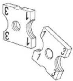
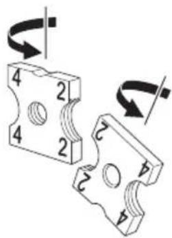
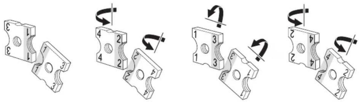
As is shown in Fig. 24, repeated cutting can cause breaking and warping of the cutter edge. Using the cutter in this condition can produce burr on the cutting location of the studs so that the threads are distorted. This will prevent clean cuts and make it impossible to insert the nut.
As is shown in Fig. 25, the edge is found on four locations on the cutter. Use the method described in Fig. 27 to change the attachment direction of the cutter to allow a total of four usages.
If the nut does not fit on the stud due to breaking and warping of the edge, change the cutter attachment direction to use the edge without breaking and warping or replace with a new cutter.
2. Changing the cutter attachment direction or replacing the cutter
(1) Before removing:
[1] Set the forward/reverse switching button to the lock position (Fig. 4 (b)).
[2] Remove the rechargeable battery from the main unit.
(2) Removal
Use the accessory hex. bar wrench to remove the hex. socket hd. bolt. It is now possible to remove the cutter and spacer (Fig. 26).
(3) Before attaching
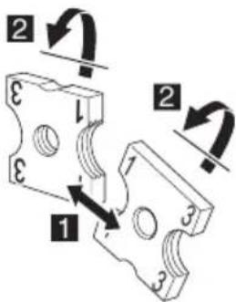
[1] There are four cutting locations on the cutter. As shown in Fig. 27, by changing the installation position of the cutter it is possible to use the cutter four times.
[2] When changing the installation position of the cutter, the cutters must be in the correct positions in relation to each other.
When viewing from the front (cover side) of the tool body, place the notches on the sides of the cutters so that the parts
[3] If there is breakage or warping on the cutter edge or if there are bulges on the cutter attachment surface, use a file to the areas flat.
[4] Use brush to remove the filings attached to the cutter attachment groove on the bracket.
CAUTION
- As shown in Fig. 5 (b), if the cutters are combined in such a way that both side without the notch on the cutter or both notch sides are facing out, the pitch of the threads on the studs and the threads on the cutter will not be in agreement. This can cause damage to the cutter edge or cause wear to premature damage to the main unit. - If using a cutter that does not have numbers engraved, use the notch as a visual guide when changing the attachment orientation of the cutter. The method for changing the orientation is the same as for Fig. 27.
(4) Attachment
[1] When using an M6, M8, M10, W5/16 cutter Insert the cutter in the cutter attachment groove on the bracket insert the special spacer and W3/8 spacer between the cutter and bracket and then use the hex. Socket hd. Bolt to tighten and secure. (Fig. 28)
[2] When using an M12, W3/8 cutter Insert the cutter in the cutter attachment groove on the bracket insert the special spacer between the cutter and bracket and then use the hex. Socket hd. Bolt to tighten and secure. (Fig. 28)
NOTE
Spacers are not required when using W1/2 cutter.
CAUTION
○ The hex. socket hd. bolt should be sufficiently tightened with the hexagonal wrench.
○ Use special cutters and spacers that conform with the size of the stud. Using cutters and spacers of the wrong size or confusing them can lead to damage to the stud and cutter.
MAINTENANCE AND INSPECTION
WARNING
Be sure to remove the rechargeable battery from the unit during inspection and cleaning.
1. Care after use
After use, clean it with a brush, etc., especially around the cutting location of the cutter.
2. Inspecting the mounting screws
Regularly inspect all mounting screws and ensure that they are properly tightened. Should any of the screws be loose, retighten them immediately. Failure to do so could result in serious hazard.
3. Cleaning on the outside
When the power tool is stained, wipe with a soft dry cloth or a cloth moistened with soapy water. Do not use chloric solvents, gasoline or paint thinner, for they melt plastics.
4. Inspection of terminals (tool and battery)
Check to make sure that swarf and dust have not collected on the terminals. On occasion check prior, during and after operation.
CAUTION
Remove any swarf or dust which may have collected on the terminals.
Failure to do so may result in malfunction.
5. Storage
Store the power tool and battery in a place in which the temperature is less than 40^ C and out of reach of children.
NOTE
Storing lithium-ion batteries.
Make sure the lithium-ion batteries have been fully charged before storing them.
Prolonged storage (3 months or more) of batteries with a low charge may result in performance deterioration, significantly reducing battery usage time or rendering the batteries incapable of holding a charge.
However, significantly reduced battery usage time may be recovered by repeatedly charging and using the batteries two to five times.
If the battery usage time is extremely short despite repeated charging and use, consider the batteries dead and purchase new batteries.
6. HiKOKI Authorized Service Center:
See https://hikoki-powertools.eu for addresses.
CAUTION
In the operation and maintenance of power tools, the safety regulations and standards prescribed in each country must be observed.
Important notice on the batteries for the HiKOKI cordless power tools
Please always use one of our designated genuine batteries. We cannot guarantee the safety and performance of our cordless power tool when used with batteries other than these designated by us, or when the battery is disassembled and modified (such as disassembly and replacement of cells or other internal parts).
GUARANTEE
We guarantee HiKOKI Power Tools in accordance with statutory/country specific regulation. This guarantee does not cover defects or damage due to misuse, abuse, or normal wear and tear. In case of complaint, please send the Power Tool, undismantled, with the GUARANTEE CERTIFICATE found at the end of this Handling instruction, to a HiKOKI Authorized Service Center.
NOTE
Due to HiKOKI's continuing program of research and development, the specifications herein are subject to change without prior notice.
Information concerning airborne noise and vibration The measured values were determined according to EN62841 and declared in accordance with ISO 4871.
Measured A-weighted sound power level: 78 dB (A) Measured A-weighted sound pressure level: 70 dB (A) Uncertainty K: 1.5 dB (A).
Wear hearing protection.
Vibration total values (triax vector sum) determined according to EN62841.
Stud cutting: Vibration emission value ah < 0.8 m/s² Uncertainty K = 1.5 m/s²
The declared vibration total value and the declared noise emission value have been measured in accordance with a standard test method and may be used for comparing one tool with another. They may also be used in a preliminary assessment of exposure.
WARNING
☐ The vibration and noise emission during actual use of the power tool can differ from the declared total value depending on the ways in which the tool is used especially what kind of workpiece is processed; and
○ Identify safety measures to protect the operator that are based on an estimation of exposure in the actual conditions of use (taking account of all parts of the operating cycle such as the times when the tool is switched off and when it is running idle in addition to the trigger time).
ALLGEMEINE
natural_image
Line drawing of a mechanical device with internal components (no text or symbols)(BSL1830, BSL1840, BSL1850, BSL1860)
natural_image
Line drawing of a portable electronic device with control panel and display (no text or symbols)(BSL36..18)
- Schneider
natural_image
Simple line drawing of a rectangular device with a central screen and side connectors (no text or symbols)PRÉCAUTIONS LORS DE LA CONNEXION DU DISPOSITIF USB (UC18YSL3)
natural_image
Line drawing of a mechanical device with internal components (no text or symbols)(BSL1830, BSL1840, BSL1850, BSL1860)

natural_image
Line drawing of a battery pack with control panel and buttons (no text or symbols)(BSL36..18)
2. Cutter
| Taille de la vis filetée | Assemblage des cutters et entretoises | |
| M12 | M12 Cutter (×2)M12 Entretoise (×2) | 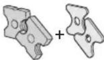 |
| M10 | M10 Cutter (×2)M10 Entretoise (×2) | |
| M8 | M8 Cutter (×2)M8 Entretoise (×2) | |
| M6 | M6 Cutter (×2)M6 Entretoise (×2) | |
| W1/2 W1/2 Cutter (×2) | 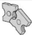 | |
| W3/8 | W3/8 Cutter (×2)W3/8 Entretoise (×2) | 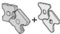 |
| W5/16 | W5/16 Cutter (×2)W5/16 Entretoise (×2) | |
3. Ebarboir
natural_image
Line drawing of a mechanical device with internal components (no text or symbols)(BSL1830, BSL1840, BSL1850, BSL1860)

natural_image
Line drawing of a battery pack (no text or symbols)(BSL36..18)
- Fresa
natural_image
Line drawing of a mechanical device with internal components (no text or symbols)(BSL1830, BSL1840, BSL1850, BSL1860)
natural_image
Line drawing of a battery pack with control panel and buttons (no text or symbols)(BSL36..18)
- Knip-element
| Afmeting draadeind | Kombineren van knip-elementen en vulplaatjes. | |
| M12 | M12 Knip-element (×2)M12 Vulplaatje (×2) | 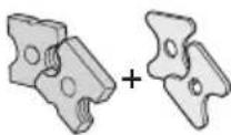 |
| M10 | M10 Knip-element (×2)M10 Vulplaatje (×2) | |
| M8 | M8 Knip-element (×2)M8 Vulplaatje (×2) | |
| M6 | M6 Knip-element (×2)M6 Vulplaatje (×2) | |
| W1/2 | W1/2 Knip-element (×2) | 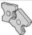 |
| W3/8 | W3/8 Knip-element (×2)W3/8 Vulplaatje (×2) | 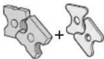 |
| W5/16 | W5/16 Knip-element (×2)W5/16 Vulplaatje (×2) | |
- Trimmer
| Afmeting draadeind | 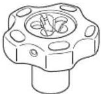 |
| M12 | |
| M10 | |
| M8 | |
| M6 | |
| W1/2 | |
| W3/8 | |
| W5/16 |
4. Schouderriem
natural_image
Line drawing of a mechanical device with internal components (no text or symbols)(BSL1830, BSL1840, BSL1850, BSL1860)
natural_image
Line drawing of a portable electronic device with control panel and display (no text or symbols)(BSL36..18)
2. Cortador
| Tamaño de la varilla con rosca | Combinación de cortadores y separadores | |
| M12 | M12 Cortador (×2)M12 Separador (×2) | 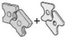 |
| M10 | M10 Cortador (×2)M10 Separador (×2) | |
| M8 | M8 Cortador (×2)M8 Separador (×2) | |
| M6 | M6 Cortador (×2)M6 Separador (×2) | |
| W1/2 W1/2 Cortador (×2) | 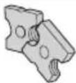 | |
| W3/8 | W3/8 Cortador (×2)W3/8 Separador (×2) |  |
| W5/16 | W5/16 Cortador (×2)W5/16 Separador (×2) | |
3. Desbastador
natural_image
Line drawing of a mechanical device with internal components (no text or symbols)(BSL1830, BSL1840, BSL1850, BSL1860)

natural_image
Line drawing of a battery pack with control panel and buttons (no text or symbols)(BSL36..18)
- Cortador
natural_image
Line drawing of a mechanical device with internal components (no text or symbols)(BSL1830, BSL1840, BSL1850, BSL1860)

natural_image
Line drawing of a portable electronic device with control panel and display (no text or symbols)(BSL36..18)
- Skär
natural_image
Line drawing of a mechanical device with internal components (no text or symbols)(BSL1830, BSL1840, BSL1850, BSL1860)

natural_image
Line drawing of a battery pack with control panel and display (no text or symbols)(BSL36..18)
2. Kutter
| Gevindstang størrelse | Sammensætning af kuttere og afstandsskiver | |
| M12 | M12 kutter (×2)M12 afstandsskive (×2) | 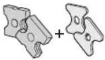 |
| M10 | M10 kutter (×2)M10 afstandsskive (×2) | |
| M8 | M8 kutter (×2)M8 afstandsskive (×2) | |
| M6 | M6 kutter (×2)M6 afstandsskive (×2) | |
| W1/2 W1/2 kutter (×2) | 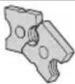 | |
| W3/8 | W3/8 kutter (×2)W3/8 afstandsskive (×2) | 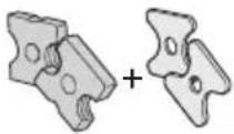 |
| W5/16 | W5/16 kutter (×2)W5/16 afstandsskive (×2) | |
3. Trimmer
| Gevindstang størrelse |  |
| M12 | |
| M10 | |
| M8 | |
| M6 | |
| W1/2 | |
| W3/8 | |
| W5/16 |
4. Skulderrem
natural_image
Line drawing of a mechanical device with ports and internal components (no text or symbols)(BSL1830, BSL1840, BSL1850, BSL1860)

natural_image
Line drawing of a battery pack with control panel and buttons (no text or symbols)(BSL36..18)
- Kutter
| Gjengestag-størrelse | Kuttere pluss mellomstykker | |
| M12 | M12 Kutter (×2)M12 Mellolstykke (×2) | 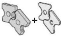 |
| M10 | M10 Kutter (×2)M10 Mellolstykke (×2) | |
| M8 | M8 Kutter (×2)M8 Mellolstykke (×2) | |
| M6 | M6 Kutter (×2)M6 Mellolstykke (×2) | |
| W1/2 | W1/2 Kutter (×2) | 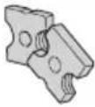 |
| W3/8 | W3/8 Kutter (×2)W3/8 Mellolstykke (×2) | 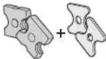 |
| W5/16 | W5/16 Kutter (×2)W5/16 Mellolstykke (×2) | |
- Trimmer
VEDLIKEHOLD OG INSPEKSJON
ADVARSEL
natural_image
Line drawing of a mechanical device with internal components (no text or symbols)(BSL1830, BSL1840, BSL1850, BSL1860)
natural_image
Line drawing of a portable electronic device with control panel and display (no text or symbols)(BSL36..18)
- Leikkuri
natural_image
Line drawing of a mechanical device with internal components (no text or symbols)(BSL1830, BSL1840, BSL1850, BSL1860)

natural_image
Line drawing of a portable electronic device with control panel and display (no text or symbols)(BSL36..18)
- Κόφτης
natural_image
Line drawing of a mechanical device with ports and casing (no text or symbols)(BSL1830, BSL1840, BSL1850, BSL1860)

natural_image
Line drawing of a portable electronic device with control panel and display (no text or symbols)(BSL36..18)
- Nożyce
OKRES EKSPLOATACYJNY I WYMIANA NOŻYC
natural_image
Line drawing of a mechanical device with internal components (no text or symbols)(BSL1830, BSL1840, BSL1850, BSL1860)

natural_image
Line drawing of a battery pack with control panel and display (no text or symbols)(BSL36..18)
- Daraboló
natural_image
Line drawing of a mechanical device with internal components (no text or symbols)(BSL1830, BSL1840, BSL1850, BSL1860)

natural_image
Line drawing of a battery pack with control panel and buttons (no text or symbols)(BSL36..18)
- Střihač
natural_image
Line drawing of a mechanical device with internal components (no text or symbols)(BSL1830, BSL1840, BSL1850, BSL1860)

natural_image
Line drawing of a portable electronic device with control panel and buttons (no text or symbols)(BSL36..18)
- Kesici
natural_image
Line drawing of a mechanical device with internal components (no text or symbols)(BSL1830, BSL1840, BSL1850, BSL1860)
natural_image
Line drawing of a battery pack with control panel and display (no text or symbols)(BSL36..18)
| Dimensiune bolt |  |
| M12 | |
| M10 | |
| M8 | |
| M6 | |
| W1/2 | |
| W3/8 | |
| W5/16 |
4. Curea de umăr
natural_image
Line drawing of a mechanical device with internal components (no text or symbols)(BSL1830, BSL1840, BSL1850, BSL1860)

natural_image
Line drawing of a portable electronic device with control panel and display (no text or symbols)(BSL36..18)
- Rezalnik
| Velikost navojne palice | Kombinacija rezalnikov in distančnikov | |
| M12 | Rezalnik M12 (×2)Distančnik M12 (×2) |  |
| M10 | Rezalnik M10 (×2)Distančnik M10 (×2) | |
| M8 | Rezalnik M8 (×2)Distančnik M8 (×2) | |
| M6 | Rezalnik M6 (×2)Distančnik M6 (×2) | |
| W1/2 | Rezalnik W1/2 (×2) | 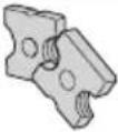 |
| W3/8 | Rezalnik W3/8 (×2)Distančnik W3/8 (×2) |  |
| W5/16 | Rezalnik W5/16 (×2)Distančnik W5/16 (×2) | |
- Obrezovalnik
| Velikost navojne palice | 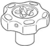 |
| M12 | |
| M10 | |
| M8 | |
| M6 | |
| W1/2 | |
| W3/8 | |
| W5/16 |
4. Naramnica
| Velikost navojne palice | Mehko jeklo* (S235JR) | Nerjaveče jeklo* (EN 1.4301) |
| W5/16 Pribl. | 2100 — | |
| W3/8 Pribl. | 1400 Pribl. 750 | |
| W1/2 Pribl. | 400 — | |
| M6 Pribl. 3 | 150 — | |
| M8 Pribl. 1 | 850 — | |
| M10 Pribl. | 1150 — | |
| M12 Pribl. | 770 — |
natural_image
Line drawing of a mechanical device with no visible text or symbols(BSL1830, BSL1840, BSL1850, BSL1860)
natural_image
Line drawing of a portable electronic device with control panel and buttons (no text or symbols)(BSL36..18)
Slovenčina
- Rezačka
| Vel'kos'tyče | Kombinácia rezačiek a podložiek | |
| M12 | Rezačka M12 (×2)Podložka M12 (×2) | 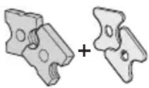 |
| M10 | Rezačka M10 (×2)Podložka M10 (×2) | |
| M8 | Rezačka M8 (×2)Podložka M8 (×2) | |
| M6 | Rezačka M6 (×2)Podložka M6 (×2) | |
| W1/2 Rezačka | W1/2 (×2) |  |
| W3/8 | Rezačka W3/8 (×2)Podložka W3/8 (×2) | 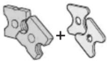 |
| W5/16 | Rezačka W5/16 (×2)Podložka W5/16 (×2) | |
- Orezávač
natural_image
Simple line drawing of a rectangular device with a central screen and side connectors (no text or symbols)ПРЕДПАЗНИ МЕРКИ ЗА СВЪРЗВАНЕ НА USB УСТРОЙСТВО (UC18YSL3)
natural_image
Line drawing of a mechanical device with internal components (no text or symbols)(BSL1830, BSL1840, BSL1850, BSL1860)

natural_image
Line drawing of a battery pack with control panel and display (no text or symbols)(BSL36..18)
- Резачка
natural_image
Line drawing of a mechanical device with ports and casing (no text or symbols)(BSL1830, BSL1840, BSL1850, BSL1860)

natural_image
Line drawing of a battery pack with no text or symbols(BSL36..18)
- Rezač
| Veličina navojne šipke | Kombinirke i odstojnici | |
| M12 | M12 rezač (×2)M12 odstojnik (×2) | 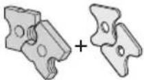 |
| M10 | M10 rezač (×2)M10 odstojnik (×2) | |
| M8 | M8 rezač (×2)M8 odstojnik (×2) | |
| M6 | M6 rezač (×2)M6 odstojnik (×2) | |
| W1/2 | W1/2 rezač (×2) |  |
| W3/8 | W3/8 rezač (×2)W3/8 odstojnik (×2) | 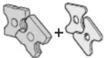 |
| W5/16 | W5/16 rezač (×2)W5/16 odstojnik (×2) | |
- Trimer
| Veličina navojne šipke |  |
| M12 | |
| M10 | |
| M8 | |
| M6 | |
| W1/2 | |
| W3/8 | |
| W5/16 |
4. Rameni kaiš
Kačenjem visećeg ramenog kaiša na kuku (A) koja je uključena sa ovim proizvodom, možete da nosite proizvod kao što je prikazano na SI. 23.
OPREZ
O Prilagodite rameni kaiš na pravilnu dužinu pre korišćenja.
O Ne koristite rameni kaiš ako je oštećen.
| Veličina navojne šipke | Mek čelik* (S235JR) | Nerđajući čelik* (EN 1.4301) |
| W5/16 Pribl. | 2100 — | |
| W3/8 Pribl. | 1400 Pribl. 750 | |
| W1/2 Pribl. | 400 — | |
| M6 Pribl. 3 | 150 — | |
| M8 Pribl. 1 | 850 — | |
| M10 Pribl. | 1150 — | |
| M12 Pribl. | 770 — |
natural_image
Simple line drawing of a rectangular device with a central screen and side connectors (no text or symbols)Hrvatski
MJERE PREDOSTROŽNOSTI SPAJANJA USB UREĐAJA (UC18YSL3)
natural_image
Line drawing of a mechanical device with internal components (no text or symbols)(BSL1830, BSL1840, BSL1850, BSL1860)

natural_image
Line drawing of a portable electronic device with a display and control panel (no text or symbols)(BSL36..18)
- Rezač
| Veličina šipke | Kombinirani rezači i odstojnici | |
| M12 | M12 rezač (×2)M12 odstojnik (×2) | 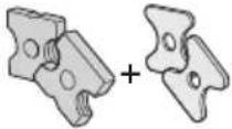 |
| M10 | M10 rezač (×2)M10 odstojnik (×2) | |
| M8 | M8 rezač (×2)M8 odstojnik (×2) | |
| M6 | M6 rezač (×2)M6 odstojnik (×2) | |
| W1/2 | W1/2 rezač (×2) |  |
| W3/8 | W3/8 rezač (×2)W3/8 odstojnik (×2) |  |
| W5/16 | W5/16 rezač (×2)W5/16 odstojnik (×2) | |
Hrvatski
- Trimer
| Veličina šipke | 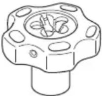 |
| M12 | |
| M10 | |
| M8 | |
| M6 | |
| W1/2 | |
| W3/8 | |
| W5/16 |
4. Naramenica
natural_image
Line drawing of a quill pen in an inkwell (no text or symbols)| English | Dansk | Română | |||
| GUARANTEE CERTIFICATE1 Model No.2 Serial No.3 Date of Purchase4 Customer Name and Address5 Dealer Name and Address(Please stamp dealer name and address) | GARANTIBEVIS1 Modelnummer2 Serienummer3 Købsdato4 Kundes navn og adresse5 Forhandlers navn og adresse(Indsæt stempel med forhandlers navn og adresse) | CERTIFICAT DE GARANTIE1 Model nr.2 Nr. de serie3 Data cumpărării4 Numele și adresa clientului5 Numele și adresa distribuitorului(Vă rugăm aplicați štampila cu numele și adresa distribuitorului) | |||
| Deutsch | Norsk | Slovenščina | |||
| GARANTIESCHEIN1 Modell-Nr.2 Serien-Nr.3 Kaufdatum4 Name und Anschrift des Kunden5 Name und Anschrift des Händlers(Bitte mit Namen und Anschrift des Handlers abstempeln) | GARANTISERTIFIKAT1 Modellnr.2 Serienr.3 Kjøpsdato4 Kundens navn og adresse5 Forhandlerens navn og adresse(Vennligst stemple forhandlerens navn og adresse) | GARANCIJSKO POTRDILO1 Št. modela2 Serijska št.3 Datum nakupa4 Ime in naslov kupca5 Ime in naslov prodajalca(Prosimo vitisnite žig z imenom in naslovom prodajalca) | |||
| Français | Suomi | Slovenčina | |||
| CERTIFICAT DE GARANTIE1 No. de modèle2 No de série3 Date d'achat4 Nom et adresse du client5 Nom et adresse du revendeur(Cachet portant le nom et l'adresse du revendeur) | TAKUUTODISTUS1 Malli nro2 Sarja nro3 Ostopăivămâäră4 Asiakkaan nimi ja osoite5 Myyjăn nimi ja osoite(Leimaa myyjăn nimi ja osoite) | ZÁRUČNÝ LISTA1 Č. modelu2 Sériové č.3 Dátum zakúpenia4 Meno a adresa zákazníka5 Názov a adresa predajcu(Pečiatka s názvom a adresou predajcu) | |||
| Italiano | Ελληνικά | Български | |||
| CERTIFICATO DI GARANZIA1 Modello2 N° di serie3 Data di acquisto4 Nome e indirizzo dell'acquirente5 Nome e indirizzo del rivenditore(Si prega di apporre il timbro con questi dati) | ПІЗТОПОІНТИКО ЕГГУНЄНЕ1 Ap. Movtėlou2 Aŭξων Ap.3 Нμερομηνία αγοράς4 ́Оvoμα και διεŭθυνση πελάτη5 ́Оvoμα και διεŭθυνση μεταπωλητή(Παρακαλούμε να χρησιμοποιηθεί σφραγίδα) | ГАРАНЦИОНЕН СЕРТИФИКАТ1 Модел No2 Сериен No3 Дата за закупуване4 Име и адрес на клиента5 Име и адрес на търговеца(Моля, отпечатайте името и адрес на дильра) | |||
| Nederlands | Polski | Srpski | |||
| GARANTIEBEWIJS1 Modelnummer2 Seriennummer3 Datum van aankoop4 Naam en adres van de gebruiker5 Naam en adres van de handelaar(Stempel a.u.b. naam en adres vande de handolaar) | GWARANCJA1 Model2 Numer seryjny3 Data zakupu4 Nazwa klienta i adres5 Nazwa dealera i adres(Pieczęć punktu sprzedaży) | GARANTNI SERTIFIKAT1 Br. modela.2 Serijski br.3 Datum kupovine4 Ime i adresa kupca5 Ime i adresa prodavca(Molimo da stavite pečat na ime i adresu trgovca) | |||
| Español | Magyar | Hrvatski | |||
| CERTIFICADO DE GARANTÍA1 Número de modelo2 Número de serie3 Fecha de adquisición4 Nombre y dirección del cliente5 Nombre y dirección del distribuidor(Se ruega poner el sello del distribuidor con su nombre y dirección) | GARANCIA BIZONYLAT1 Tipusszám2 Sorozatszám3 A vásárlás dátuma4 A Vásárló neve és címe5 A Kereskedő neve és címe(Kérjük ide elhelyezni a Kereskedő nevének és címének pecsétjét) | JAMSTVENI CERTIFIKAT1 Br modela.2 Serijski br.3 Datum kupnje4 Ime i adresa kupca5 Ime i adresa trgovca(Molimo stavite pečat na ime i adresu trgovca) | |||
| Português | Čeština | ||||
| CERTIFICADO DE GARANTIA1 Número do modelo2 Número do série3 Data de compra4 Nome e morada do cliente5 Nome e morada do distribuidor(Por favor, carímbe o nome e morada do distribuidor) | ZÁRUČNÍ LIST1 Model č.2 Série č.3 Datum nákupu4 Jméno a adresa zákazníka5 Jméno a adresa prodejce(Prosíme o razítko se jménem a adresou prodejce) | ||||
| Svenska | Türkçe | ||||
| GARANTICERTIFIKAT1 Modellnr2 Serienr3 Inköpsdatum4 Kundens namn och adress5 Försäljarens namn och adress(Stämpla försäljarens namn och adress) | GARANTI SERTÍFİKASI1 Model No.2 Seri No.3 Satin Alma Tarihi4 Müşteri Adı ve Adresi5 Bayi Adı ve Adresi(Lütfen bayi adını ve adresini kaşe olarak basın) | ||||

HiKOKI
| 1 | |
| 2 | |
| 3 | |
| 4 | |
| 5 |