
YT-85553 - DJ Equipment Yato - Free user manual and instructions
Find the device manual for free YT-85553 Yato in PDF.

| Product Type | Zero-Turn Lawn Tractor (Zero-Turn) |
| Brand | Yato |
| Model | YT-85553 |
| Category | Powered Garden Equipment |
| Engine | 1-cylinder, 4-stroke, 546 cc, 11 kW (15 hp) at 2800 rpm |
| Fuel Type | Unleaded gasoline E10, octane rating ≥95 |
| Engine Oil Type | SAE 15W-40 |
| Fuel Tank Capacity | 5 L |
| Oil Tank Capacity | 1.6 L |
| Starting System | Electric (12 V, 12 Ah battery) |
| Cutting Width | 1066 mm (42 inches) |
| Cutting Height | 40 to 120 mm, adjustable to 6 positions |
| Wheel Diameter (Front/Rear) | 11" (297 mm) / 18" (457 mm) |
| Recommended Tire Pressure | 24 PSI (1.65 bar) |
| Weight | 225.5 kg |
| Sound Level (Acoustic Power) | 98.19 dB(A) ± 0.8 |
| Vibration Level (Hand-Arm) | Left: 9.156 ± 1.5 m/s²; Right: 8.907 ± 1.5 m/s² |
| Vibration Level (Whole Body) | 3.306 ± 1.5 m/s² |
| Battery Type | Maintenance-free lead-acid, 12 V / 12 Ah |
| Spark Plug | RN9YC (gap 0.7–0.8 mm) |
| Air Filter | Type T420 (paper element + foam) |
| Fuse | Type and amperage indicated on the fuse (replace with identical) |
| Maximum Working Slope | 10° (do not mow on steeper slopes) |
| Maintenance | Oil change every 25 h, air filter every 25 h, spark plug every 100 h, blades every 2 years or 50 h |
| Spare Parts Available | Fuel cap (YT-861945), drive belt (YT-861950), V-belt (YT-861951), blade (YT-861952), deck wheel (YT-861953) |
| Warranty | Void if used improperly or modified |
Frequently Asked Questions - YT-85553 Yato
User questions about YT-85553 Yato
0 question about this device. Answer the ones you know or ask your own.
Ask a new question about this device
Download the instructions for your DJ Equipment in PDF format for free! Find your manual YT-85553 - Yato and take your electronic device back in hand. On this page are published all the documents necessary for the use of your device. YT-85553 by Yato.
USER MANUAL YT-85553 Yato
natural_image
Exterior view of a grassy golf cart with visible wheels and side-mounted equipment (no text or symbols)CE
PL EN DE RU UA LT LV CZ SK HU RO ES FR IT NL GR BG PT HR AR

natural_image
Top-down technical diagram of a vehicle's internal components, showing engine, fan, and exhaust system (no text or labels)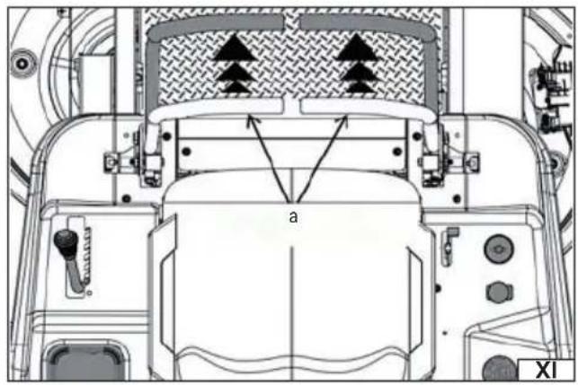
natural_image
Technical diagram of a vehicle's front and rear assembly with no visible text or symbols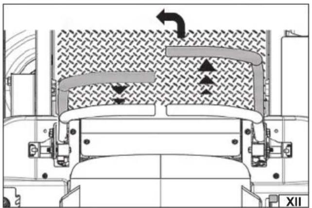
natural_image
Technical diagram of a mechanical assembly with directional arrows and labeled section XII (no readable text or symbols)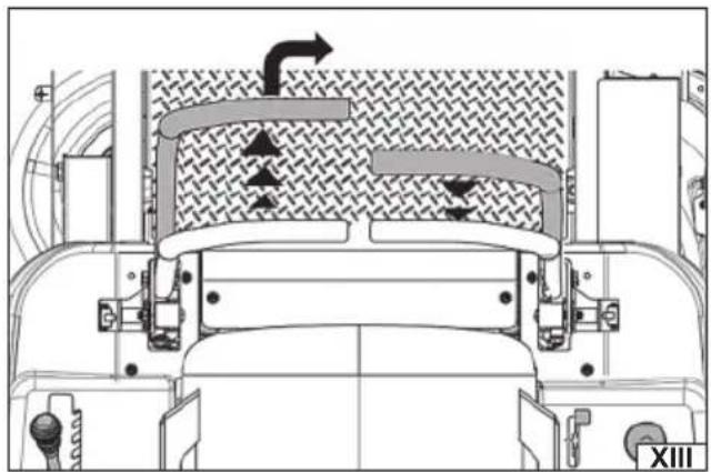
natural_image
Technical diagram of a vehicle interior showing airflow paths and structural components (no text or labels)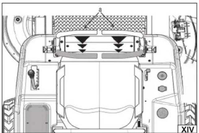
natural_image
Top-down technical diagram of a vehicle's rear wheel assembly showing structural components and airflow direction (no text or labels)PL EN DE RU UA LT LV CZ SK HU RO ES FR IT NL GR BG PT HR AR
natural_image
Technical diagram of a vehicle interior showing engine, valve, and exhaust components (no text or labels)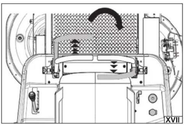
natural_image
Technical diagram of a mechanical assembly with no visible text or symbols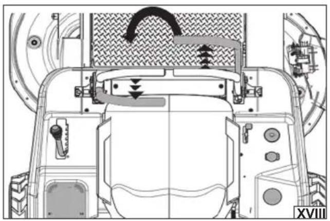
natural_image
Technical line drawing of a vehicle's rear view showing engine, dashboard, and wheel components (no text or symbols)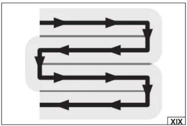
flowchart
graph TD
    A["Start"] --> B["Path 1"]
    B --> C["Path 2"]
    C --> D["..."]
    D --> E["End"]
    style A fill:#000,stroke:#000,color:#fff
    style E fill:#000,stroke:#000,color:#fff
    style B fill:#000,stroke:#000,color:#fff
    style C fill:#000,stroke:#000,color:#fff
    style D fill:#000,stroke:#000,color:#fff
    style E fill:#000,stroke:#000,color:#fff
    subgraph Path 1
        direction TB
        A --> B --> C --> D --> E
    end
    subgraph Path 2
        direction TB
        B --> C --> D --> E
    end
    subgraph Path 3
        direction TB
        C --> D --> E
    end
    subgraph Path 4
        direction TB
        D --> E
    end
natural_image
Close-up of a mechanical component with a circular button and directional arrow, no visible text or symbols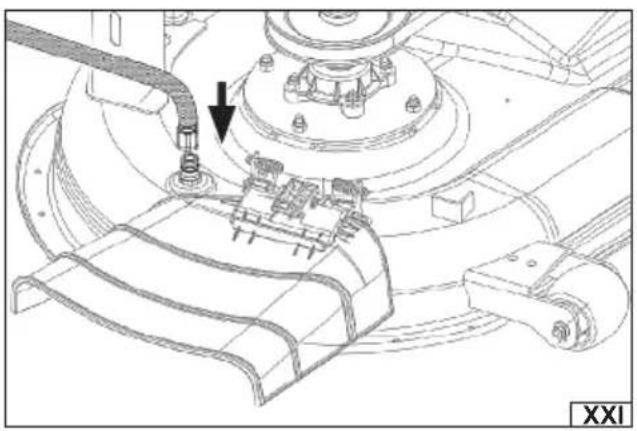
natural_image
Technical line drawing of a mechanical assembly with a pipe and bracket (no text or symbols)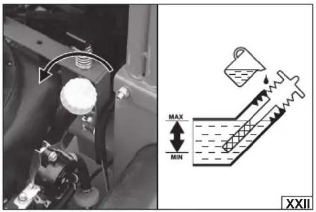
PL EN DE RU UA LT LV CZ SK HU RO ES FR IT NL GR BG PT HR AR

natural_image
Close-up of a mechanical component with a black arrow pointing to a small feature, no visible text or symbols.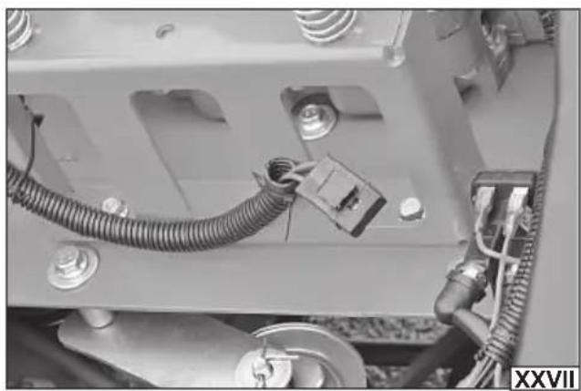
natural_image
Close-up of a mechanical assembly with coiled cable and connector (no visible text or symbols)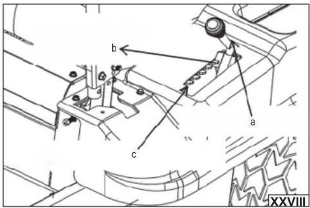
natural_image
Mechanical assembly diagram showing gears and shafts with no visible text or symbols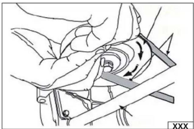
natural_image
Mechanical diagram showing hands operating a tool with motion arrows indicating movement (no text or symbols)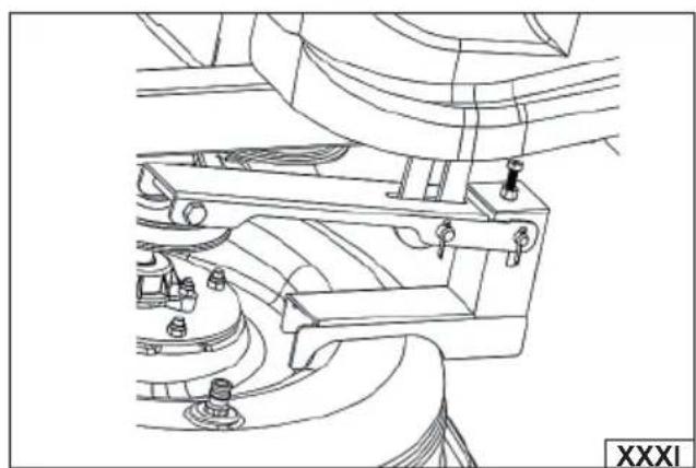
natural_image
Technical line drawing of a mechanical assembly with no visible text or symbolsPL EN DE RU UA LT LV CZ SK HU RO ES FR IT NL GR BG PT HR AR
natural_image
Technical line drawing of a mechanical assembly with no visible text or symbols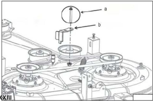
natural_image
Technical line drawing of a mechanical assembly with pulleys and gears (no text or symbols)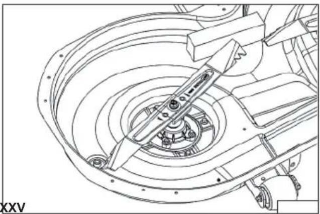
natural_image
Technical line drawing of a mechanical assembly with concentric circular components and no visible text or symbols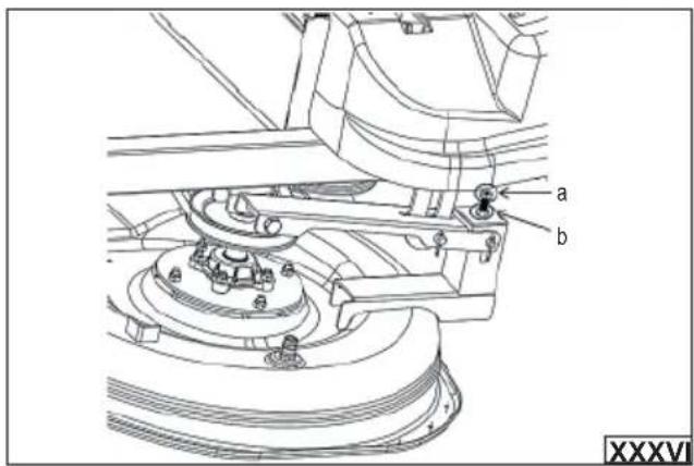
natural_image
Technical line drawing of a mechanical assembly with no visible text or symbolsPL
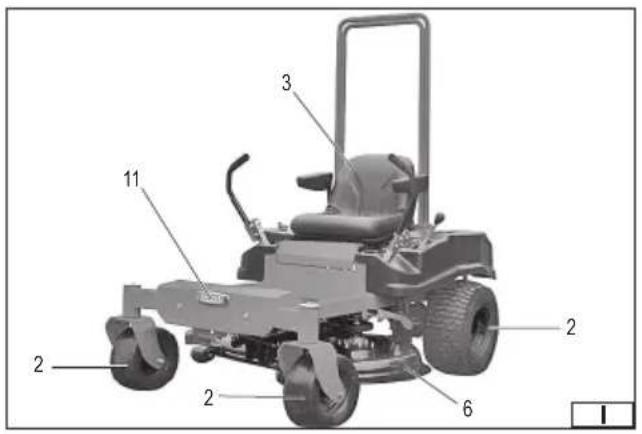
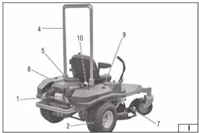
- engine
- wheel
- operator seat
- protective frame
- protective frame holder
- cutting unit housing
- ejection hole cover
- air fi lter
- fuel fi ller cap
- oil fi ller cap
- lighting
DE
Read the operating instruction
Wear hearing protectors
Beware of ejected objects
No entry for unauthorized persons, especially children, near the machine during operation
Attention - Do not touch the rotating blade!
Attention, toxic fumes or toxic gases. Do not use the machine indoors.
Explosion hazard. Do not fill the fuel tank while the engine is running. Do not smoke while refueling
Do not use the machine on slopes with an incline greater than 10 degrees. Risk of overturning!
Stay away from bystanders
PRODUCT CHARACTERISTICS
Tractor - zero-turn petrol lawn mower is a machine powered by a combustion engine, designed for effective mowing of lawns, especially on large surfaces and in places requiring precise maneuvers. The mower is operated by an operator sitting on the machine. Thanks to the zero-turn technology, it is possible to quickly turn on the spot, which increases maneuverability and shortens the working time. Correct, reliable and safe operation of the machine depends on proper use, therefore:
Before operating the machine, read the entire manual and keep it.
The supplier is not liable for any damage or injury resulting from use of the machine for purposes other than its intended use, failure to comply with safety regulations and recommendations in this manual. Use of the machine for purposes other than its intended use also results in loss of the user's rights to warranty and guarantee.
EQUIPMENT
The mower is delivered complete, but assembly is required before first use.
TECHNICAL DATA
| Parameter Unit of measurement Value | ||
| Catalogue number YT-85553 | ||
| Number of cylinders 1 | ||
| Number of bars 4 | ||
| Fuel type Unleaded petrol E10 | ||
| Type of oil SAE15W-40 | ||
| Engine capacity [cm] | ^3 ] 546 | |
| Maximum power [kW] 11 | ||
| Maximum RPM [min] | ^-1 ] 2800 | |
| Cooling | By air | |
| Start-up type | Electric | |
| Fuel tank capacity | [I] | 5 |
| Oil tank capacity | [I] | 1.6 |
| Spark plug type RN9YC | ||
| Air filter type | T420 | |
| Battery type | Lead-acid | |
| Battery nominal voltage | [V] | 12 |
| Battery capacity | [Ah] | 12 |
| Maximum grass cutting width | [mm] | 1066 |
| Diameter of front and rear wheels | ["/mm] | 11"/297, 18"/457 |
| Cutting height | [mm] | 40-120 |
| Mass | [kg] | 225.5 |
| Left/right hand-arm vibration level | [m/s ?] | 9.156 ± 1.5 / 8.907 ± 1.5 |
| Whole body vibration level | [m/s ?] | 3.306 ± 1.5 |
| Noise level | ||
| sound pressure | [dB(A)] | 86 ± 3.0 |
| sound power | [dB(A)] | 98.19 ± 0.8 |
SAFETY INSTRUCTIONS
IMPORTANT!
BEFORE USE, READ THE USER'S MANUAL CAREFULLY
LEAVE FOR FUTURE USE
Teaching
Read the instructions carefully. Familiarize yourself with the controls and proper use of the machine. If you pass on the machine to another person, include the operating instructions. The machine should always be used in accordance with the recommendations in the operating instructions.
Do not allow children or people unfamiliar with the machine's operating instructions to operate the device.
Do not mow when other people, especially children or pets, are nearby. Before starting work, designate a safety zone that is
EN
off-limits to other people and pets. Maintain a radius of at least five meters around the mower while it is in operation.
Please remember that the operator or user is responsible for accidents or hazards occurring to other people or the surroundings.
Preparation
When working, always wear sturdy shoes and long trousers, do not work barefoot or in sandals.
Personal protective equipment such as safety goggles and hearing protection should be worn during work. The use of personal protective equipment such as dust masks, eye protection, safety shoes, helmets and hearing protection reduces the risk of serious personal injury.
Keep hair, clothing and work gloves away from moving parts of the machine. Loose clothing, jewelry or long hair can get caught in moving parts of the machine and become entangled, which could cause serious injury.
Avoid wearing worn-out clothing that is too loose or has hanging belts or ribbons. Loose clothing can become caught in moving machine parts, which can cause injuries.
Before starting work, thoroughly inspect the area where the machine will be working and remove all stones, branches, wires, bones, toys and other foreign objects. Caught objects can cause damage to the machine, they can also be thrown at high speed, which is a threat to the operator and the surroundings.
Before turning on the machine, remove any wrenches or other tools that have been used for adjustments. A wrench left attached to a rotating part of the machine can cause serious personal injury.
Before mowing, check the terrain thoroughly. Working on unfamiliar terrain can lead to dangerous situations. Do not work on uneven, potholed or bumpy terrain. Watch out for protruding roots. Long grass can hide bumps and obstacles. Uneven or bumpy terrain can cause the machine and operator to tip over, resulting in serious injury or even death.
Before use, always check that the blades and mounting screws are not worn or damaged. Replace worn blades and screws before starting work. Also check that the screw connections have not become loose. Tighten any loose screws.
Use
WARNING! Do not operate the machine in closed rooms or in confined spaces where dangerous carbon monoxide (CO) fumes can accumulate. Fuel exhaust and fumes are toxic. Poisoning them can lead to accidents and cause serious injury or even death.
Do not work when tired or under the influence of medication, alcohol or drugs. Even a moment of inattention while working can result in serious bodily injury.
Mow only in daylight or with good artificial light.
Do not mow in the rain. If possible, avoid mowing wet grass.
WARNING! Do not operate the machine where there is a risk of lightning discharge.
Use extreme caution when operating on slopes or when changing direction on a slope. Do not suddenly change direction or speed when operating on slopes. Do not mow on excessively steep slopes. Make sure that it is safe to operate the machine when operating on a slope. Move slowly when operating on a slope. When operating on a slope, mow across the slope, not up or down. Do not start or stop on a slope. If traction is lost on a slope, disengage the blade drive and then slowly steer the machine down the slope. Never exceed the maximum permissible operating angle on slopes.
Do not use this machine on slopes greater than 10 degrees.
The engine must be turned off if the machine is to be tilted when moving it over surfaces other than grass, or when transporting it to and from the mowing area.
It must be ensured that all safety systems, including start interlocks and operator presence control systems, are functioning properly.
Do not use the mower without the discharge guard properly installed and lowered down.
Start the engine according to the instructions, making sure your feet are away from the blades.
Do not place hands or feet near rotating parts. Make sure that the discharge opening is not clogged at all times.
Stop the lawn mower engine:
- every time the operator needs to leave the station
- before refi lling with fuel or engine oil
- before cleaning the outlet
- before cleaning, checking, replacing accessories or repairing the device
- after being hit by a foreign object. Check the mower for damage and repair it if necessary before restarting.
- if the device starts to vibrate excessively (check immediately)
NOTE! After the engine is turned off, the blade continues to rotate for some time. Wait until the blade has come to a complete stop. If the machine begins to vibrate excessively:
- check for damage,
- replace or repair any damaged part,
- check and tighten loose parts.
Maintenance and storage
WARNING! Disconnect the spark plug before making adjustments, changing accessories, or storing the machine. This will prevent the machine from starting accidentally.
EN
Before starting maintenance, wait until the machine and all its components have completely cooled down.
Keep all nuts, bolts and screws in proper condition to be sure the equipment is in safe operating condition.
Do not store lawn mower with fuel in the tank.
Make sure the storage area is away from sources of ignition.
Always wear safety glasses when adjusting, maintaining or repairing the machine.
Replace worn or damaged parts for safety reasons.
Be careful when adjusting the device to avoid entrapment of fingers between the moving blades and fixed parts of the mower.
Do not change the sealed engine speed settings. Changing the factory engine speed settings can result in damage to the machine or even a fire.
Regularly check that all start interlocks and operator presence control systems are working properly. Failure to properly operate the machine's safety systems can cause accidents.
Please maintain your lawn mower regularly and keep it clean and in good working condition.
Do not disconnect or modify machine guards. Improper operation of guards can cause accidents.
Only use original spare parts and accessories. The use of inappropriate accessories can result in damage to the machine and/or serious injury.
Make sure the correct type of knives are used.
ADDITIONAL SAFETY INSTRUCTIONS
Recommended fuel: E10 unleaded petrol with a minimum octane rating of 95.
You should use fuel and oil free of any impurities, and designed for four-stroke engines. It is recommended to use high-quality products. This will extend the life of the engine.
Regularly check the engine oil level. Using the mower with too low an oil level or no oil at all can damage it or even cause a fire.
Before starting work, make sure that the mower is properly assembled.
Do not expose the machine to moisture. Do not use the mower during precipitation or when there is a risk of lightning. Do not use it in damp or wet environments.
Before using the machine, it is recommended that you ask the dealer or a specialist to demonstrate how to use the machine safely and effectively.
Do not modify the machine in any way. Do not use replacement blades other than the original ones.
Always wear work clothes, gloves, closed footwear and safety glasses to protect against mechanical hazards.
If the mower behaves suspiciously during operation (increased vibrations, noise, smell, etc.), the mower should be turned off immediately and taken to a repair shop.
After replacing the blade, before restarting the mower, make sure that the blade rotates freely and without obstruction. The blade must be accurately balanced before assembly.
Before starting the engine or beginning operation, become familiar with all machine controls.
Only original spare parts should be used for repairs and maintenance.
Engine ventilation openings must always be unobstructed and clean.
Do not operate the lawnmower in closed or unventilated rooms. Exhaust gases contain substances harmful to health and must not be inhaled.
The fuel supply system should be checked periodically. If you notice any leaks, take the device to an authorized service center for repairs.
Wait until the engine reaches rated speed before mowing.
Do not cover the ventilation inlets and outlets. Even when the mower is not operating.
Before transporting the lawn mower, it is essential to empty the fuel tank.
Do not touch the engine surfaces that become hot during operation, as this may result in burns.
Fuel is highly flammable! Do not fill the fuel tank while the machine is running or hot. Fill the fuel tank outdoors. Do not fill the fuel tank near an open flame. Do not spill fuel. If fuel is spilled, dry it thoroughly before starting the mower. Tighten the fuel tank cap securely.
Before leaving the operator's position, stop the machine, disengage the blade drive, swing the drive control levers completely out to the neutral position, turn off the engine and remove the key from the ignition. Before leaving the operator's position, wait until all moving parts have come to a complete stop.
Never discharge grass towards people, animals, vehicles, buildings, windows or other objects and surfaces that may be damaged.
After finishing work, remove the key from the ignition to prevent unauthorized persons from using the machine.
It is forbidden to carry passengers! People and animals should be at a safe distance from the machine while it is running.
Before driving, look behind you and to the sides of the tractor, especially before reversing.
Do not modify the engine or other mechanisms of the lawn mower in any way.
Do not use the lawn mower without a properly installed air filter.
MOWER ASSEMBLY
Preparation for assembly
The product should be unpacked from the packaging and all packaging elements should be removed. It is recommended to keep
EN
the packaging, which may be useful during transport or storage of the product. Check whether none of the product parts have been damaged during transport, any observed damage, e.g. cracks or deformations, disqualify the product from further use until they are repaired or the damaged parts are replaced.
It is recommended to place the machine on a flat, hard and clean surface.
Personal protective equipment such as protective gloves, eye protection and protective clothing should be worn during installation. NOTE! If you need to mount or dismount accessories during operation, always stop the machine, disengage the blade drive, make sure both machine drive levers are fully outward in neutral, then stop the engine and remove the ignition key. Wait until all machine components have cooled down completely, then disconnect the spark plug wire.
Manually moving the machine
It is possible to move the machine by hand without having to start the engine. To do this, engage the transmission override levers located at the rear of the tractor, behind each rear wheel. Pull out both transmission override levers (a), turn them clockwise (b) and lock them in place, as shown in illustration (II). Once the machine has been moved, disengage the transmission override levers by performing steps (a) and (b) in reverse order.
Installing the operator protection frame (I)
The operator's protective frame must be mounted to the brackets located behind the operator's seat using the mounting screws and nuts. It is prohibited to use the machine without a properly mounted protective frame.
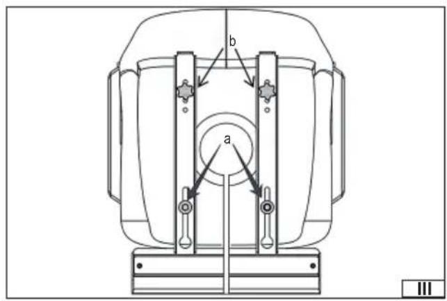
Installing and adjusting the operator's seat
To assemble the operator's seat, follow the instructions below. First, remove all the straps securing the seat assembly and control levers for transport. Be especially careful not to damage the wiring harness connecting the microswitch located under the seat to the operator presence detection system on the seat. Then, unscrew the two screws and two knobs located on the seat base. After completing these steps, the seat should be turned to the correct position and pre-secured to the guides using previously unscrewed screws (a) and knobs (b) as shown in illustration (III). Adjusting the seat to the operator's height is possible in several available positions by securing the seat in the appropriate holes in the guides using the fastening knobs. It is recommended to make the final adjustment of the seat after all the machine components have been completely assembled. After completing the adjustment, tighten the screws and knobs securing the seat to the guides firmly and securely and make sure that the seat does not change its position during operation.
During installation, be careful not to pinch or damage the wiring harness.
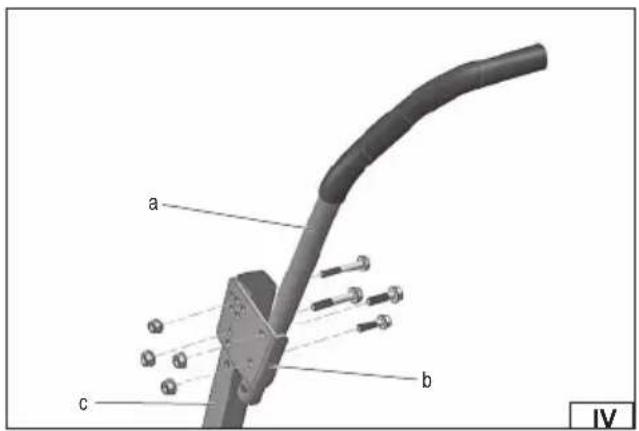
Assembly and adjustment of the machine drive control levers
The machine's drive control levers have been lowered or dismantled for transport. Before using the tractor, they must be properly installed and set. These levers can be mounted in one of two available height positions and can be moved forward or backward within the slot in the bracket, adjusting their position to ensure comfortable operation of the machine.
As shown in illustration (IV), attach the lever (a) to the bracket (b), and then attach the connected parts to the lever holder (c) using the mounting screws (d) and nuts (e), without fully tightening the screws. After completing these steps, make sure that the control lever (a) is in line with the lever holder (c), and then repeat the above steps for the other lever so that the other control lever is attached and set in the same position. After completing the adjustment of both control levers, tighten the mounting screws firmly and securely to prevent the levers from moving during operation.
Installing the side discharge guard
CAUTION! Operating the machine without the side discharge guard or with the side discharge guard incorrectly fitted is prohibited. The guard must be in the lowered position during operation.
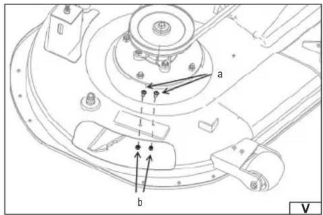
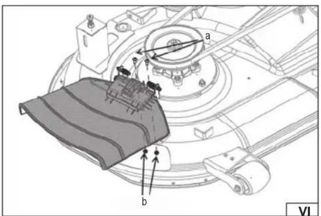
Before using the mower, the side discharge guard must be installed. If there are any keys attached to the guard mount using a cable tie, remove them before starting assembly. Remove the screws (a) and nuts (b) from the guard mount located on the mower housing, as shown in illustration (V). The side discharge guard should be attached to the mount using the screws (a) and nuts (b) as shown in illustration (VI), and then tighten all the components until the side discharge guard is securely and safely attached to the mower housing.
Connecting the battery
NOTE! During battery installation, pay special attention to avoid short-circuiting the battery terminals.
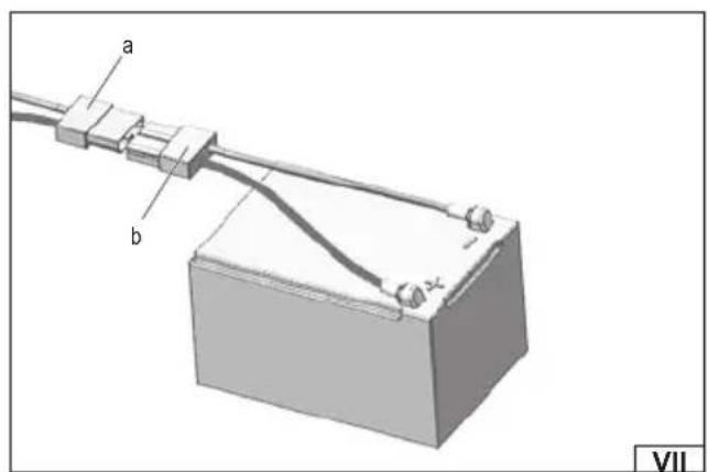
To install the battery, tilt the seat to the vertical position. As shown in illustration (VII), connect the machine electrical connector (a) to the battery connector (b). The connectors can only be connected in one correct way. Make sure that the battery is properly secured to the base in the machine frame using the mounting clamp and mounting screws and that it does not change position during operation.
PREPARING FOR WORK
NOTE! The engine may only have a small amount of oil in it from the factory to protect it during transport and storage. Before first start-up, check the engine oil level and then top up to the required level. The oil level should be checked
EN
regularly and topped up as necessary. Starting the machine without oil or with too little oil in the gearbox can lead to irreversible engine damage.
You should prepare oil intended for four-stroke engines with a viscosity class of SAE 15W40.
Before adding oil, place the machine on a flat surface, open the engine cover, and then, as shown in the illustration (XXII), unscrew the oil filler cap and wipe the attached oil dipstick dry. Fill the tank with oil. When filling, it is recommended to use a funnel or a filler to avoid spilling oil. If oil spills, wipe off any residue before starting the engine. Check that the oil level is correct. To do this, insert the dipstick into the filler hole and screw on the oil filler cap. Then unscrew it and check the oil level on the dipstick. The oil level should be between the maximum and minimum levels on the dipstick (XXII). After making sure that the oil level is correct, close the oil filler hole with the cover.
NOTE! The oil level should be checked before each start of work. Never check the oil level while the engine is running. Stop the engine before adding oil.
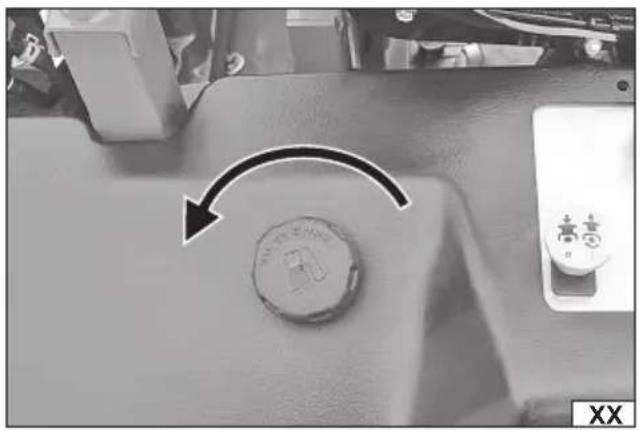
After adding oil, add fuel. The fuel is unleaded petrol with an octane rating of at least 95. To add fuel, unscrew the fuel tank filler cap as shown in illustration (XX) and pour fuel into the tank. When adding fuel, it is recommended to use a filler or funnel to reduce the risk of fuel spilling. If fuel spills, wipe off any remaining fuel thoroughly. Wait until the vapors have completely dissipated and start the engine in a different place than where fuel was filled. After adding fuel, close the fuel tank filler cap. After adding oil and fuel, close the engine cover.
The rear axle of the tractor is equipped with pneumatic wheels. The recommended tire pressure is 24 PSI / 1.65 BAR. The tires must be inflated before starting work. Do not exceed the recommended tire pressure. Always inflate the tires to an even pressure. Incorrect or uneven tire pressure can cause uneven mowing and lead to dangerous situations such as the machine tipping over on its side, which can cause serious injury or even death.
NOTE! Before each start of work, check that the air pressure in the tires is correct.
Before starting work, check that the machine is not damaged, is properly assembled and that all safety elements are properly attached. If it is found that the machine is incomplete or damaged, further work is prohibited!
From the work area, remove all visible stones, roots, wires, toys and other obstacles that can be caught by the machine blades and thrown in another direction. Special attention should be paid to electrical wires so that they do not end up in the work area. Leaving electrical wires in the work area can lead to damage to the wires, which can result in electric shock or even death.
Battery charging
CAUTION! The battery must be charged away from sources of fire. Do not smoke while charging the battery. Keep the battery away from sparks. Ignition of gases released from the battery may cause the battery to explode.
CAUTION! Never start the engine unless the battery is fully charged. Before starting the engine, make sure the battery is fully charged.
CAUTION! Before starting charging, make sure that the power supply body, cable and plug are not cracked or damaged. It is forbidden to use a faulty or damaged charger! Only the charger supplied with the machine may be used to charge the battery. Using another charger may cause a fire or irreversible damage to the battery. The battery may only be charged in a closed, dry room protected from access by unauthorized persons, especially children. The charger must not be used without constant adult supervision! If it is necessary to leave the room where charging is taking place, disconnect the charger from the mains by unplugging the power supply from the mains socket. If smoke, a suspicious smell, etc. is emitted from the charger, the charger plug must be removed from the mains socket immediately!
The mower is equipped with a maintenance-free lead-acid battery that does not require electrolyte level control. In the event of longer storage, e.g. during the winter, it is recommended to charge the battery once every three months to prevent damage due to discharge. In the event of a situation in which starting the machine is difficult or impossible, the battery should be charged. If the battery cannot be charged, it should be replaced with a new one. The battery should always be replaced with an original one, identical to the one that was factory-fitted to the mower. The used battery should not be disposed of with household waste, the battery should be disposed of in accordance with local regulations.
To ensure a long battery life, it is important to maintain it carefully. Failure to follow this procedure or charging the battery incorrectly can cause permanent damage to its components. The device's battery must always be charged:
- before using the device for the first time after purchase.
- before leaving the device unused for a long period of time.
- before starting the device after a long period of non-use.
- a discharged battery should be charged as soon as possible.
The machine is equipped with a battery charging socket located under the operator's seat. To charge the battery, raise the operator's seat, connect the charger plug to the battery charging socket, and then connect the charger to the mains socket. The red diode will light up, indicating the charging process. When charging is complete, the red diode will turn off and the green diode will light up, indicating the battery is fully charged. Unplug the charger plug from the mains socket, and then disconnect the charger plug from the battery charging socket. When the battery is charged, close the engine cover.
Below is a description of the machine controls, shown in illustration (VIII):
a. Machine Drive Control Levers - The right and left drive control levers are located on either side of the operator's seat and provide forward (D) and reverse (R) travel. The levers are hinged, allowing them to swing outward to allow the operator to enter or exit the tractor. To start the engine, the levers must be fully outward, in the neutral (N) position, which also engages the parking brake. Each lever controls the corresponding drive transmission – right or left, controlling all the movements of the tractor. Driving and steering the tractor using these levers is different from operating traditional tractors and requires practice. Detailed instructions on how to operate the levers are provided later in the manual.
b. Cutting height adjustment lever – this lever allows you to change the cutting height within the range given in the technical data table. The lever can be set in one of 6 cutting height adjustment positions, where position 1 corresponds to the lowest and position 6 to the highest possible cutting height. To change the cutting height, move the lever sideways by sliding it out of the guide bar socket, and then after setting the desired height, move the lever sideways, locking it in the guide bar socket.
Attention! Attention! Before driving the mower on a road or sidewalk, raise the cutting unit to the maximum cutting height and disengage the blade drive.
c. Ignition switch – used to start and stop the engine using the key. To start the engine, place the key in the ignition, turn and hold the key in the position marked with the start symbol – START, until the engine starts, then immediately release the pressure on the key. To turn the engine off, turn the key to the off position – STOP.
d. Blade drive switch – this switch allows you to engage or disengage the blade drive. Lifting the switch up will engage the blade drive, which will cause the blades to start rotating. Pressing the switch down will disengage the blade drive.
ATTENTION!
The blades may continue to rotate for a few seconds after the blade drive is disengaged.
Before starting the engine, make sure that the blade drive is disengaged – the blade drive switch should be pressed in.
Always keep hands and feet away from rotating blades, discharge chute and moving engine parts.
Before leaving your position, disengage the blade drive and make sure the blades have stopped rotating.
Always disengage the blade drive before driving the machine on a sidewalk or road.
e. Throttle control lever – allows you to increase or decrease engine speed. To start a cold engine, push the throttle lever all the way forward to the choke position, marked with a hare symbol. As the engine warms up, set the lever to a position between the hare symbols (faster RPM) and the tortoise symbols (slower RPM). After each change of throttle lever position, wait until the engine is running smoothly. The speed at which the throttle lever returns depends on the atmospheric conditions in which the engine is started. The lower the ambient temperature, the slower the return must be.
During normal operation and when mowing grass, increase the engine speed by moving the throttle lever to the position marked with the hare symbol. When moving from one mowing area to another, it is recommended to set the lever to the position between the hare and tortoise symbols.
Note! The maximum engine speed that can be set using the throttle lever is factory-set for maximum engine performance. Do not change the sealed engine speed settings. Increasing the factory-set engine speed can damage the machine's engine or even cause a fire.
Machine safety system
The machine is equipped with a safety system that protects the operator from potential hazards during use. If the safety system is not working properly, do not use the machine until it is repaired.
The safety system prevents the engine from starting unless the right and left drive control levers are fully outward in the neutral position and the blade drive is disengaged.
The safety system automatically turns off the engine if the operator leaves the seat with the blade drive engaged.
Note! The blade drive must be disengaged to restart the engine.
The safety system disengages the blade drive and stops the mower blades from rotating if both drive control levers are moved to the reverse position. To re-engage the blade drive, the levers must be in neutral or in the forward position and the blade drive switch must be pressed to disengage the blade drive and then lifted to re-engage the blade drive.
Machine safety system check procedure
Note! Some checks may only be possible after starting the engine. The procedure for starting the internal combustion engine is provided later in this manual.
Regular inspection of the safety system is essential to ensure the machine is working properly. To perform the inspection, follow these steps:
Engage the blade drive. Then momentarily turn the ignition key to the start position – the engine should not start.
Move both drive control levers fully inward to the neutral position, then release the operator seat – the engine should stop.
EN
Set both drive control levers fully out to neutral (with the parking brake engaged), engage the blade drive, then release the operator's seat - the engine should stop.
Start the tractor and set the drive control levers to neutral. Engage the blade drive and slowly move both drive control levers backwards, slowly moving backwards – the blade drive should disengage and the mower blades should stop.
After performing the above tests, make sure that all safety system functions are working properly. If any irregularities are detected, immediately stop using the machine and contact the manufacturer's authorized service.
Checking machine safety and performance
Before starting work, check that the machine is not damaged, is properly assembled and prepared for work and that the safety system is working properly. If it is found that the machine is not properly prepared for work, is incomplete, has damage or any of the safety systems do not work properly, further work is prohibited!
Do not start mowing if you feel excessive vibration from the cutting blades or if you are not sure that the blades are sharp enough. Poorly sharpened blades tear the grass and cause the lawn to turn yellow. A loose, damaged or incorrectly fitted blade can cause vibration and also cause dangerous situations!
Starting the combustion engine
WARNING! The machine is equipped with a safety system to protect the operator. Do not use the machine if any of the safety system components are not working properly. The safety system should be checked regularly to ensure safe operation of the machine.
NOTE! Before starting the engine, make sure that the blade drive is disengaged – the blade drive switch is pressed.
Take the operator position on the seat.
According to illustration (IX):
Make sure the left (a) and right (b) machine drive control levers are fully outward in the neutral position (parking brake engaged). Make sure the blade drive is disengaged – the drive switch (e) is pressed.
Note! If the engine is warm, it may not be necessary to move the throttle lever (c) to the choke position, marked with the hare symbol, to start the engine.
Move the throttle lever (c) fully forward to the choke position, marked with the hare symbol.
Insert the key into the ignition (d) and turn it clockwise to the START position, then release the key immediately after the engine starts. Do not crank the engine continuously for more than 5 seconds. If the engine does not start within this time, turn the key to the STOP position and wait at least 15 seconds for the starter to cool down. After this time, try again. If after several attempts the engine still will not start, do not continue cranking with the throttle valve in the choke position, as this could flood the spark plug and make restarting the engine difficult.
After starting, as the engine warms up, set the throttle lever (c) to a position between the hare symbols (faster RPM) and the tortoise symbol (slower RPM). After each change of the throttle lever position, wait until the engine is running smoothly. The speed of the throttle lever return depends on the weather conditions in which the engine is started. The lower the ambient temperature, the slower the return must be.
Before starting work, make sure that the engine runs smoothly.
Stopping the combustion engine
According to illustration (IX):
Make sure the blade drive is disengaged – the drive switch (e) is pressed.
Make sure the left (a) and right (b) machine drive control levers are fully outward in the neutral position (parking brake engaged).
Set the throttle lever (c) to the mid-position between idle and maximum engine speed.
Turn the ignition key (d) counterclockwise to the STOP position, then remove the key.
Caution! Always remove the key from the ignition after stopping the engine to prevent accidental engine starting and battery discharge when the machine is left unattended.
First use – exercises before starting work
Operating a zero-turn tractor is different from operating a traditional self-propelled tractor. Because a zero-turn tractor is more maneuverable, it takes some practice to master the controls.
It is recommended to designate a suitable, level place for practice in an open area, to which no unauthorized persons or animals will have access. Before starting to use it, it is recommended to practice operating the tractor for about 30 minutes.
Carefully transport the tractor to the designated practice area. The blade drive should be disengaged during practice. During practice, operate the throttle lever at approximately 1/2-3/4 of the full range and do not use maximum speed in either forward or reverse. Practice carefully maneuvering the tractor according to the information below on operating the tractor. Practice until you can safely operate the machine.
Preparing to drive a tractor
WARNING! When operating the machine, avoid sharp turns, excessive speed and sudden stops.
Make sure the operator's seat is adjusted to the most comfortable position to allow easy access to the controls. For detailed seat
EN
adjustment information, refer to the „Assembling and Adjusting the Operator's Seat „ section of the manual.
As shown in illustration (X), move both drive control levers (a) fully inward to the neutral position, which will release the parking brake.
Note! The drive control levers must be moved fully inward to the neutral position before you can start moving forward or reverse. In this position, the parking brake is released. Parking the tractor on uneven ground or on a slope can cause the brakes to lock. If this happens, the tractor will not move until the levers are reset. In this situation, gently move the levers in the opposite direction to relieve the load on the brakes and allow them to release completely.
Note! If the control levers are not in the neutral position, the control levers must be readjusted as described in the instruction section „Assembly and adjustment of the machine drive control levers”.
Move the throttle lever to the maximum engine speed position, marked with the hare symbol.
Note ! Although the machine's engine is designed to operate at its maximum possible RPM, it is recommended to operate the tractor at a lower RPM setting during practice, gradually increasing it as you gain experience.
WARNING! Always keep your hands on the drive control levers. Do not release the levers by releasing them to slow the tractor. Use your hands to move the levers to the neutral position.
To begin moving forward, firmly grasp both drive control levers, then follow the instructions below.
Driving the tractor forward
WARNING! All movements of the drive control levers should be performed slowly and smoothly. Sudden movements of the levers can affect the stability of the tractor and cause it to tip over, which could result in serious injury or death to the operator.
According to the illustration (XI):
Slowly and evenly move both drive control levers (a) slowly forward. The machine will begin to move forward.
The further the drive control levers (a) are moved forward, the greater the tractor's travel speed.
To slow down the machine, move the drive control levers slowly rearward or move them to the neutral position to stop the machine.
WARNING! Always keep your hands on the drive control levers. Do not release the levers by releasing them to slow the tractor.
Use your hands to move the levers to the neutral position.
Turning the tractor while driving forward
WARNING! When changing direction, it is recommended to make gradual U-turns where possible. Sharper turns increase the risk of turf damage and may affect tractor control. Always slow down before making a sharp turn.
To turn the tractor while driving forward, the drive control levers must be moved accordingly – one lever should be moved backwards relative to the other. The tractor will turn in the direction of the lever moved backwards.
To turn left, move the left drive control lever rearward relative to the right, as shown in illustration (XII).
To turn right, move the right drive control lever rearward relative to the left, as shown in illustration (XIII).
The greater the difference in position between the two levers, the sharper the tractor will turn.
To rotate around your own axis, move the lever responsible for the steering direction to the neutral position while simultaneously moving the other lever forward.
Note: Performing a spin on grass can significantly increase the risk of damaging the turf.
Driving a tractor backwards
WARNING! Before reversing, make sure that the area around the machine is clear of obstacles and bystanders, children and animals. Do not turn near building walls, trees or other fixed obstacles to avoid dangerous situations. Be especially careful when reversing and always look to the rear.
Before reversing, stop the tractor by moving both drive control levers to the neutral position (a). Once the machine has come to a complete stop, slowly and evenly move both drive control levers rearward as shown in illustration (XIV). The tractor will begin to move in the opposite direction.
The further the drive control levers are moved rearward, the greater the tractor's travel speed.
To slow down the machine, move both drive control levers slowly forward or move them to the neutral position to stop the machine.
Turning the tractor while driving backwards
To turn the tractor while reversing, the drive control levers must be set correctly – one lever should be moved forward relative to the other. The tractor will turn in the direction of the lever moved forward.
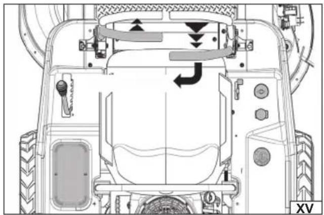
To turn left while reversing, move the left drive control lever forward relative to the right, as shown in illustration (XV).
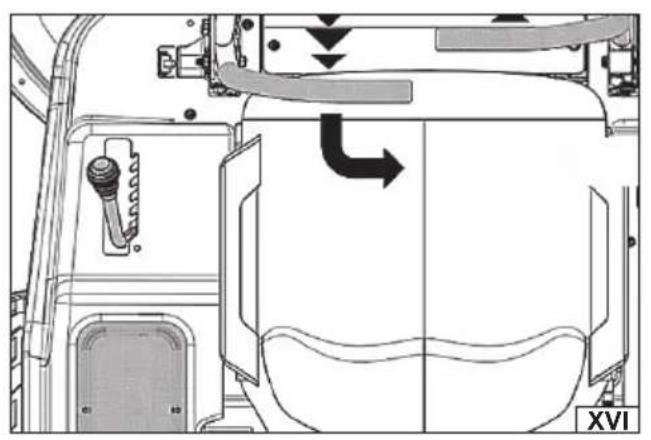
To turn right while reversing, move the right drive control lever forward relative to the left, as shown in illustration (XVI).
The greater the difference in position between the two levers, the sharper the tractor will turn.
To turn around your own axis, move the lever responsible for the turn direction to the neutral position while simultaneously moving the other lever rearward.
Note: Performing a spin on grass can significantly increase the risk of damaging the turf.
Making a zero radius turn
WARNING! The tractor must be completely stopped when making a zero turn. Making a zero turn while the tractor is moving can significantly reduce control of the machine and lead to serious damage to the lawn.
EN
Stop the tractor by moving both drive control levers to the neutral position.
To turn right (clockwise), move the left drive control lever forward while moving the right lever rearward, as shown in illustration (XVII).
To turn left (counterclockwise), move the right drive control lever forward while moving the left lever rearward, as shown in illustration (XVIII).
Stopping the tractor
Move both drive control levers to the neutral position to stop tractor movement.
Disengage the blade drive by pressing the blade drive switch.
Raise the cutting deck to the highest cutting height using the cutting height adjustment lever.
If it is necessary to leave the tractor, move the drive control levers fully outward to the neutral position, which will engage the parking brake. Then move the throttle lever to the idle position and turn the engine off by turning the ignition key to the STOP position and removing it.
WARNING! Do not leave the operator's seat without first disengaging the blade drive and setting the drive control lever outward to neutral with the parking brake engaged. Always turn off the engine and remove the key from the ignition when leaving the tractor unattended.
Blade drive operation/mowing
WARNING! Do not engage the blade drive when the cutting unit is in a low position on the grass. This can result in premature wear of the belt drive and the blade drive clutch. Before engaging the blade drive, raise the cutting unit completely or move the tractor to an area without grass.
To engage the blade drive:
Move the throttle lever to the medium speed position in the medium speed position.
Lift the blade drive switch to the on position.
Move the throttle lever to the maximum engine speed position.
Move the drive control levers forward slowly and steadily to move the tractor toward the designated point while maintaining the appropriate operating speed.
The operator must remain in the seat at all times when the machine is in operation. If the operator leaves the seat without first disengaging the blade drive, the tractor engine will shut down.
Blade drive cannot be engaged when the tractor is in reverse. Drive will automatically disengage when both drive control levers are moved to the reverse position. To re-engage the blade drive, the levers must be in neutral or forward position and the blade drive switch must be pushed to the disengaged position and then lifted back to the engaged position.
CAUTION! Always keep hands and feet away from the rotating blades, discharge opening and moving engine parts. Before leaving the operator's position, disengage the blade drive and make sure the blades have come to a complete stop. Always disengage the blade drive and raise the cutting unit to the highest position before driving the tractor on a sidewalk or road.
Recommendations when working with a lawn mower
Before starting work, prepare the area where the grass will be cut. Check that the area where the grass will be cut is free of any obstacles that could be caught by the blade and damage the mower or be thrown out and pose a hazard to the operator or bystanders.
Check the work area for electrical cables that could be cut by the blade. Damage to an electrical cable creates a risk of electric shock, which could result in serious injury or death.
Make sure that there are no bystanders or pets in the work area. If such people appear during work, first stop the mower immediately and only then warn them about the danger.
Avoid working on unstable surfaces and use caution when working on slippery surfaces.
When working with the mower, it is recommended to move the rows as shown in the illustration (XIX), maintaining equal strip widths, which should overlap slightly to ensure an even cut and avoid missing any spots.
At the end of each pass, reduce speed or stop the tractor before making a turn. It is recommended to make U-turns unless a zero turn is necessary.
Before performing a zero turn, reduce speed and then come to a complete stop.
The speed of the tractor affects the quality of the cut. Driving too fast can worsen the cutting effect. The speed should be controlled using the drive control lever.
Operate the drive control levers smoothly and avoid sudden movements when starting and stopping.
For better cutting performance and quality, it is recommended to set one of the lowest ground speeds and the highest engine speed.
Check the length of the grass and choose the cutting height. If the grass is very tall or dense, cut it in stages. Never cut more than 1/3 of the grass length. Mowing should be done regularly, making sure that the grass height does not exceed the mower's capacity. Never cut wet grass. Wet grass tends to stick inside the product, which prevents it from collecting in the basket.
Before reversing, make sure that the area around the machine is clear of obstacles and bystanders. Do not turn near building walls, trees or other fixed obstacles to avoid dangerous situations. Be especially careful when reversing.
Check all mower components before starting work. If damage is observed, do not start work until it has been removed or the damaged components have been replaced with new ones. Check that the ventilation holes are clear. If necessary, clean them with
EN
a soft brush or paintbrush. Do not use sharp or metal objects to clean the mower's ventilation holes.
Check that the screw connections are not loose. Tighten if necessary.
Check that the mower controls are clean and free of grease and other contaminants. Clean with a soft cloth if necessary.
Take regular breaks during work to avoid fatigue and overwork. This will allow you to better control the product and reduce the risk of accidents.
For better machine control, always set a safe driving speed.
Exercise particular caution when changing direction.
After finishing work, stop the machine, disengage the blade drive, make sure that both machine drive levers are fully tilted outwards in the neutral position, then stop the engine and remove the ignition key. Wait for the machine to cool down completely, disconnect the spark plug wire and start maintenance.
WARNING! If a foreign object strikes the mower during operation. Immediately stop the machine, disengage the blade drive, make sure that both machine drive levers are fully outward in the neutral position, stop the engine and remove the ignition key. Wait until all components have cooled down completely, then disconnect the spark plug cable. Then check the machine for damage. If damage is detected, do not continue working until it has been repaired. Excessive vibration during operation may be caused by damage to the mower. Stop work, disconnect the spark plug and inspect the product.
Working on the slopes
WARNING! Do not operate on slopes steeper than 10 degrees. The tractor may tip over, causing serious injury or death.
Recommendations for working on slopes
Mow across the slope, not up or down. Be especially careful when changing direction on a slope.
Watch for holes, ruts, bumps, rocks and other hidden obstacles. Uneven terrain can cause the machine to tip over. Tall grass can hide obstacles.
Use low speed. Selecting a suitably low ground speed will avoid having to stop on a slope. If traction is lost, disengage the blade drive and drive carefully down the slope.
All maneuvers on slopes should be performed slowly and smoothly. Sudden changes in speed or direction could cause the front of the tractor to lift or tip over backwards.
Things to avoid
Avoid turning when going downhill if possible. It is recommended to start at the bottom of the slope and work your way up, always slowing down before turning.
Do not mow near slopes, ditches or embankments. The tractor may suddenly tip over if a wheel is on the edge of a drop-off.
Do not attempt to stabilize the machine by placing your foot on the ground.
Do not mow wet grass. Reduced traction can cause the machine to skid.
Refueling
WARNING! Fuel is highly flammable! Observe all safety precautions when handling fuel. Do not fill the fuel tank while the machine is running. Allow the engine to cool before refueling. Do not refuel near an open flame. Do not smoke in the refueling area. Do not spill fuel. If fuel is spilled, wipe up the fuel thoroughly before starting the machine. Tighten the fuel filler cap securely. Store fuel in tightly closed, approved containers away from heat sources and out of the reach of children.
Stop the engine according to the procedure described in "Stopping the Internal Combustion Engine".
Wait for the engine to cool down.
To refuel, unscrew the fuel tank cap as shown in illustration (XX) and pour fuel into the tank. Do not fill the fuel tank above the top of the fuel tank. When filling the fuel, it is recommended to use a filler neck or funnel to reduce the risk of fuel spilling. If fuel spills, wipe off any remaining fuel thoroughly. Do not overfill the fuel tank. Wait until the vapors have completely dissipated and start the engine in a different place than where the fuel was filled. After filling the fuel tank, close the fuel tank filler neck with the cap.
Restart the engine according to the procedure in section „ Starting the combustion engine".
MACHINE MAINTENANCE
WARNING! Before performing maintenance or adjustments on the mower, stop the machine, disengage the blade drive, make sure both machine drive levers are fully outward in the neutral position, disengage the blade drive, stop the engine and remove the ignition key. Allow all components to cool completely, then disconnect the spark plug wire. Personal protective equipment such as protective gloves, eye protection and protective clothing should be worn during maintenance.
Cleaning the Lawn Mower
Before and after each use, check that the ventilation holes are clear and clean them if necessary.
After finishing work, the housing, ventilation slots, switches, covers and additional accessories should be cleaned, e.g. with an air jet (pressure not exceeding 0.3 MPa), a brush or a dry cloth without using chemicals and cleaning fluids.
Cleaning the machine
EN
After each mowing, clean the outside of the machine. Plastic parts of the casing should be cleaned with a damp sponge, water and mild detergent, taking care not to wet the engine or electrical parts of the tractor. Do not use pressure hoses or strong detergents to clean the casing and engine. Clean the steering wheel, levers and handles with a dry, clean cloth.
Avoid the build-up of grass and dirt on the top of the cutting deck cover to maintain maximum machine performance and safety. The cutting deck housing should be thoroughly cleaned of grass and dirt after each use. When cleaning the cutting blades, wear eye protection and make sure that there are no people or animals in the vicinity.
Cleaning the inside of the cutting unit
Move the tractor to a place where dispersing wet cut grass will not be a problem. Disengage the blade drive, engage the parking brake and turn off the engine.
To wash the inside of the cutting unit and collection channel:
Connect the nozzle adapter to a standard garden hose connected to a water source.
Pull back the locking ring on the nozzle adapter and place the adapter on one of the wash nozzles located on each end of the cutting unit, as shown in illustration (XXI). Release the locking ring to secure the adapter to the nozzle, then turn on the water supply. Sitting in the operator's seat, start the engine and engage the blade drive. Let the mower run for the required time. Then disengage the blade drive and turn off the engine.
Turn off the water supply.
Pull back the nozzle adapter locking ring and remove the adapter from the nozzle.
Repeat the above steps to clean the cutting assembly using the nozzle on the other side of the cutting assembly.
Cleaning the cutting unit drive
To clean the grass clippings that have accumulated around the spindle pulleys and V-belt, lower the cutting unit to the lowest position, marked „1“, and then use compressed air (pressure no greater than 0.3 MPa) to remove any remaining grass.
Regular and thorough maintenance of your lawn mower ensures its proper operation and safety of use.
Periodic inspections
Periodic inspection and maintenance of the machine components listed below should be performed.
NOTE! All maintenance procedures should be performed with the machine switched off and not working. After switching off the engine, wait until the engine and machine components have cooled down completely, and then disconnect the spark plug cable. NOTE! If the course of any service is not described below. This means that the machine must be taken to a specialist service point for this service.
NOTE! Where solvents are used for cleaning, avoid contact of the solvent with skin and eyes. Use personal protective equipment.
During the warranty period, the user may not dismantle the machine or replace any other components or parts than those listed below, as this will void the warranty. Any irregularities observed during inspection or during operation are a signal to carry out repairs at a service point. After each transport and after each 25 hours of operation, check whether the tightening of screw connections is correct.
Maintenance of the combustion engine and electrical system
Access to the engine and electrical system of the mower is located under the engine cover. To perform maintenance, open the engine cover of the mower. Before starting maintenance, make sure that all engine components have cooled down.
Checking the oil level
Unscrew the oil fi ller cap (XXII) and remove the oil level gauge.
Clean and dry the indicator with a clean cloth.
Insert the dipstick into the filler and screw on the oil filler cap. Then unscrew it and observe the indicated oil level.
If the indicated level is too low, top up the oil to the upper level of the indicator – dashed field (XXII).
Screw the dipstick into the oil filler neck.
Engine oil change
The engine oil should be changed after the first 2 to 5 hours of operation. Any subsequent oil change should be performed every 25 hours of operation.
Be careful when changing the oil. The oil is hot immediately after the engine has stopped and can cause burns. The oil tank does not have a drain hole. The used oil should be sucked out using a suction device designed for this purpose, in accordance with the suction device manufacturer's recommendations.
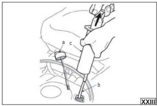
As shown in the illustration (XXIII), unscrew the oil filler cap (a), insert the tube (b) of the suction device (c) directly into the oil filler hole, and then suck out all the engine oil, remembering that the operation must be repeated several times until all the oil has been removed. After the suction operation is finished, wipe off the remaining oil.
Top up the oil according to the procedure described in section: "Preparing for work".
Note! Used engine oil must be disposed of in accordance with local regulations. It is prohibited to pour engine oil into the sewage
EN
system.
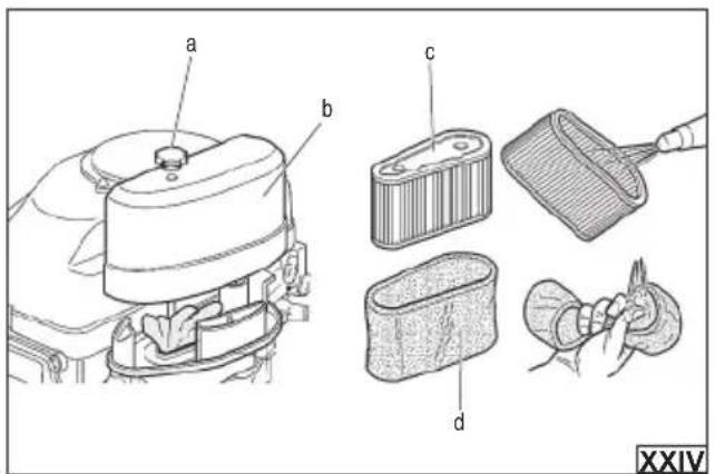
Air fi Iter maintenance (XXIV) – every 25 hours of operation
WARNING! Do not use the device without a properly installed air filter or with a damaged air filter. Otherwise, the combustion engine may suck in impurities that would normally be retained by the filter. Impurities can lead to engine malfunctions or even damage.
Depending on the model, completely unscrew the knob or knobs securing the filter housing (a), then remove the filter cover (b). Remove the filter from the base. The air filter consists of two elements – paper and foam. Carefully check each filter element for holes, tears and damage. If any filter element is damaged or cannot be cleaned during maintenance, it must be replaced with a new, defect-free one.
Clean the paper element (c) with a compressed air jet (pressure no greater than 0.2 MPa), blowing out the dirt from the inside or sucking out the dirt from the outside using a narrow vacuum cleaner brush. Due to the delicate structure of the paper filter, gentle cleaning is recommended. The paper element should not be soaked in water or any other liquid. Do not brush to avoid rubbing the dirt into the filter structure.
Clean the sponge element (d) in warm water with dishwashing liquid, rinse thoroughly and leave to dry completely. Soak the dried filter sponge in clean engine oil and squeeze out, but so that the filter remains moist.
Use a cloth slightly dampened with water to clean dirt from the inside of the filter base and the filter cover. Be careful not to allow dust or dirt to enter the line leading to the carburettor.
Place the sponge element (d) onto the paper filter element (c). Install the filter in place and close the filter cover. Make sure that the filter cover (b) is tightly closed and the filter housing mounting knobs (a) are properly tightened.
Spark plug maintenance (XXV) – every 100 hours of operation
Disconnect the wire (a) from the spark plug (b). Unscrew the spark plug with a spark plug wrench. Clean the electrodes from carbon deposits with a wire brush. Check the distance between the electrodes, it should be between 0.7 mm and 0.8 mm.
If you notice burnt electrodes or a cracked ceramic cover, replace the spark plug with a new one. The type of spark plug used is given in the technical data table.
Screw in the spark plug (b). Connect the wire to the spark plug (a).
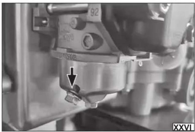
Draining the fuel system (XXVI)
NOTE! Always empty the fuel tank before storing or transporting.
CAUTION! Fuel is highly flammable! Observe all safety precautions when handling fuel. Before draining the fuel system, make sure the machine's engine is cool. Drain the fuel system outdoors. Do not drain the fuel tank near a flame. Do not smoke while draining the fuel tank.
The fuel in the lawn mower's fuel system can lose its properties over time or form a deposit that is dangerous to the engine. If the machine is to be stored for 30 days or longer, the fuel system should be drained first to prevent damage to the fuel system and engine.
Place a container with a capacity larger than the fuel tank under the drain hole.
Use a wrench to unscrew the fuel drain valve. Once the machine has been drained of fuel, close the fuel drain valve.
Wipe up any fuel residue thoroughly. Carefully remove any dry grass clippings that may have collected around the engine or muffler to prevent them from igniting the next time you use the machine!
Before refilling the fuel tank, make sure that the fuel used is fresh and free from contamination. Use good quality fuel. Never use engine or carburetor cleaners.
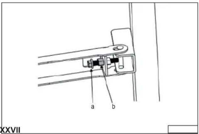
Replacing the fuse (XXVII)
The mower's electrical system and ignition switch are protected by a fuse. A blown fuse will stop the machine, in which case you should:
Raise the operator's seat to the upright position. Locate the fuse location (near the engine). Open the fuse cover, then replace the fuse with a new one of the same type and amperage. The fuse rating is indicated on the fuse. Close the fuse cover, then close the engine cover.
NOTE! A blown fuse must always be replaced with a fuse of the same type and amperage, never with a fuse of a different amperage. If the cause of the blown fuse cannot be found, contact an authorized service center of the manufacturer.
Lawn mower maintenance
WARNING! Before performing maintenance or adjustments on the mower, stop the machine, disengage the blade drive, make sure both machine drive levers are fully outward in neutral, stop the engine and remove the ignition key. Allow all components to cool completely, then disconnect the spark plug wire. Personal protective equipment such as protective gloves, eye protection and protective clothing should be worn during maintenance.
Dismantling the cutting unit
WARNING! The exhaust outlet at the rear of the tractor can be very hot and can cause serious burns. Be extremely careful
EN
when working near it. Allow the exhaust outlet to cool completely before removing the drive belt from the cutting unit pulley.
To remove the cutting unit from the tractor, proceed as follows:
Park the tractor on level ground and make sure the parking brake is engaged.
Set the cutting unit guide wheels to their highest position (lowest cutting setting).
Remove the "V" belt from the cutting unit pulley located on the bottom of the engine using one of two methods.
Releasing belt tension using a pulley
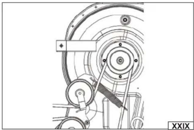
Use the cutting height adjustment lever (a) to raise the cutting deck to the highest position (c) that provides the longest horizontal belt length between the cutting deck tensioners and the cutting deck pulley located on the bottom of the engine as shown in illustration (XXVIII).
Standing at the center of the tractor, tilt the tensioner handle and the movable tensioner pulley rearward, pulling the "V" belt enough to lift it off the tensioner as shown in illustration (XXIX).
From underneath the rear of the tractor, slide the belt off the cutting unit pulley, located at the bottom of the engine.
Moving the belt off the cutterhead pulley
Using the cutting height adjustment lever (a), raise the deck to the highest position (c) that provides the longest horizontal belt length between the deck tensioners and the deck pulley located on the bottom of the engine as shown in illustration (XXVIII).
While sitting behind the tractor and looking forward, reach under the tractor and grab the belt in front of the cutting deck pulley.
WARNING! Be careful not to pinch your fingers when moving the belt off the cutter unit pulley.
Pull the left side of the belt back and down while manually turning the cutter unit pulley to the right until the belt just begins to come out over the edge of the bottom of the pulley. NOTE! If the belt is being removed from the right side, turn the pulley to the left.
While holding the belt down, continue to turn the cutter deck pulley until the belt is completely off the pulley, as shown in illustration (XXX).
Lower the cutting deck to the lowest position (b) using the cutting height adjustment lever (a), as shown in illustration (XXVIII)
Referring to illustration (XXXI), locate and then remove the cotter pin from the front deck lift rod that secures it to the frame. Then slide the rod out of the front suspension bracket.
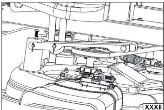
Locate the left and right cutter assembly release pins. Pull the release pins outward and disconnect the cutter assembly from the cutter assembly lift arms as shown in illustration (XXXII).
Set the cutting height adjustment lever to the highest cutting position, then slide the cutting unit out from under the tractor.
Installing the cutting unit
Set the cutting height adjustment lever to the highest cutting position (c), as shown in illustration (XXVIII).
Slide the cutting unit under the tractor from the right side, aligning the cutting unit suspension brackets and the cutting unit lift arms.
After positioning the cutting unit under the tractor, set the cutting unit lifting lever to the lowest mowing position.
NOTE! To properly align the brackets, it may be necessary to place a small block of wood under each side of the cutting unit.
Pull the release pins outward and adjust the cutting unit so that the holes in the cutting unit lift arms align with the pins as shown in illustration (XXXII).
Once aligned, press each pin fully inward through the lift arms to secure the arms in the rear suspension bracket sockets.
Reinstall the front deck lift rod and secure it with the cotter pin as shown in illustration (XXXI).
Make sure the "V" belt is on the cutting unit spindle pulleys, then route the belt rearward, under the tractor frame, over the transmission tubes, to the blade drive pulley located on the bottom of the engine.
Using the cutting height adjustment lever, raise the deck to the highest position that provides the longest horizontal belt length between the cutting deck tensioners and the blade drive pulley, located on the bottom of the engine.
Make sure the belt is positioned correctly on the cutting unit spindle pulleys and that the rear side of the belt is against both the fixed and moving belt tensioners.
Sitting behind the tractor and looking forward, make sure the belt is not twisted, then reach under the tractor and grab the belt, sliding it toward the blade drive pulley.
WARNING! Be careful not to pinch your fingers when fitting the belt over the blade drive pulley.
Pull the right side of the belt rearward and place the narrow side of the "V" belt into the groove of the cutter unit pulley as shown in illustration (XXX).
Holding the belt and pulley together, turn the pulley counterclockwise as shown in illustration (XXX). Continue turning and sliding the belt until the belt is fully seated on the blade drive pulley.
NOTE! Before starting work, carefully check the belt routing to ensure that it is properly secured.
Replacing the cutting unit drive belt
Dismantle and then slide the cutting unit out from under the tractor, following the procedure described in the “Dismantling the Cutting Unit” section of the instructions.
Unscrew the bolt (a) and nut securing the belt guard (b) to the cutting unit. Then remove the belt guard (b) as shown in illustration (XXXIII). When removing the guard, note the position of the guard and retain all fasteners so that the guard can be reinstalled
EN
correctly after replacing the belt with a new one.
Remove the belt from the cutting unit spindle pulleys.
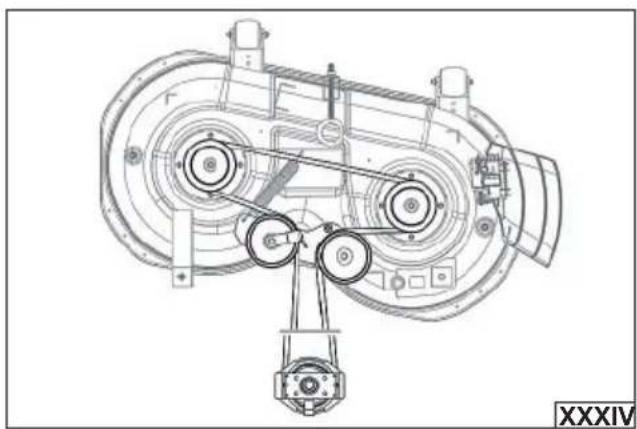
Install the new belt around the cutting unit spindle pulleys as shown in illustration (XXXIV) and then reinstall the belt cover.
Place the belt over the tension pulleys with the „V” side facing inward. Once positioned correctly, reinstall all fasteners and tighten the flange nut to secure the assembly, as shown in illustration (XXXIV).
Reinstall the cutting unit following the procedure described in the "Installing the Cutting Unit" instruction section.
Note! Make sure the belt cover is properly installed.
Replacing the cutting blades
WARNING! Before starting to replace the blades, make sure that the engine and all machine components are cool and the spark plug wire is disconnected. Wear personal protective equipment such as protective gloves, eye protection and protective clothing.
The degree of wear and damage to the blades should be checked regularly. If excessive wear, damage (chipping), excessive vibration or a drop in performance is observed during operation, the blades should be replaced with new, defect-free ones. The cutting blades should always be replaced with original ones, identical to those that were installed in the mower at the factory. Only the use of original spare parts allows you to maintain the safety of the product. In mowers equipped with two separate cutting blades, it is recommended to replace them in pairs in order to maintain the performance and safety of the product. The blades should be replaced by an experienced user. In case of doubt, contact an authorized service center of the manufacturer. The blades should be replaced every two years or every 50 hours of operation.
Dismantle the cutting assembly following the procedure described in the "Dismantling the Cutting Assembly" instruction section.
Block the blade so that it does not rotate during removal. Unscrew the blade mounting bolt completely, then remove the washer and cutting blade. Clean the inside of the mower housing, the drive shaft and the mounting adapter of dirt. Install the new blade as shown in the illustration (XXXV), so that the bent edges of the blade point upwards. Tighten the blade mounting bolt to 95-122 Nm.
Replacing the V-belt of the tractor drive transmission
Dismantling and replacing the transmission V-belt requires dismantling several components and using specialist tools. To replace the transmission V-belt, contact an authorised manufacturer's service centre.
Leveling the cutting unit
Transverse leveling of the cutting unit
Note! Before adjusting the level of the cutting unit, check the air pressure in the tractor tires. For detailed information on pressure values, see the PREPARING FOR WORK section.
Always level the cutting unit crosswise (left to right) first, and only then adjust its position lengthwise (front to back). If the blades are not cutting evenly, you can correct the level of the cutting unit by adjusting it crosswise.
Adjust as follows:
Stop the tractor on a firm, level surface. Set the cutting height lever in the middle position, between the lowest and highest cutting heights, then rotate both outer blades so that they are perpendicular to the tractor.
Measure the distance from the tip of the left blade to the ground, then the distance from the tip of the right blade to the ground.
The two measurements should be identical. If the values are different, proceed to the next step.
Loosen the screw (a), adjust the height, and then tighten the nut (b) as shown in illustration (XXXVI).
Note! The rear right mower suspension mount is non-adjustable and is used to assist in adjusting the other suspension mounts.
Longitudinal leveling of the cutting unit
Note! Before adjusting the level of the cutting unit, check the air pressure in the tractor tires. For detailed information on pressure values, see the PREPARING FOR WORK section. Always first level the cutting unit laterally (from left to right), and only then adjust its position longitudinally (front to back).
The front of the cutting unit should be 6-10 mm lower than the rear. If adjustment is necessary, follow these steps:
Stop the tractor on a level, firm surface and set the cutting height adjustment lever in the midway position between the lowest and highest cutting heights.
Turn the blade closest to the discharge opening so that it is parallel to the tractor.
Measure the distance from the front end of the blade to the ground and from the rear end of the blade to the ground. The first measurement should be 6–10 mm less than the second measurement.
Determine the approximate value of the adjustment required and, if necessary, proceed with its execution.
The illustration (XXXVII) shows: (a) nut, (b) bolt. Loosen the nut (a), then adjust the bolt (b). After adjustment, tighten the nut.
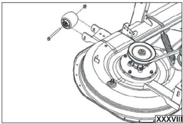
Adjusting the front guide wheels of the cutting unit
WARNING! Keep hands and feet away from the cutting unit discharge opening.
The front guide wheels of the cutting unit are designed to prevent scalping of the lawn and should not touch the ground. The height of these wheels relative to the ground should be 6-13 mm after the cutting unit has been set to the desired cutting height.
Use the cutting height adjustment lever to set the cutting unit to the desired working height, then check the distance of the guide wheels from the ground. If adjustment is necessary, follow the steps below:
EN
Visually check the distance between the front guide wheels and the ground.
If the wheels are touching the ground or very close to it, they should be lifted.
If the wheels are more than 12 mm above the ground, they must be lowered.
Unscrew the nut securing one of the front guide wheels and the bolt securing the wheel to the cutting unit. Remove the guide wheel and the securing bolt as shown in illustration (XXXVIII).
Screw the mounting screw into one of the four holes in the guide wheel holder to ensure that the wheel clearance is 6–12 mm from the ground.
Note which hole the first guide wheel is mounted in and adjust the second wheel accordingly so that it is at the same height.
Troubleshooting
Below are typical faults and possible solutions. If in any doubt, stop using the product and contact an authorized service center for the manufacturer.
| Problem Cause Solution | ||
| Excessive vibration | Loose or unbalanced cutting blade Tighten the blade and spindle | |
| Damaged or bent cutting blade Replace the blade | ||
| Uneven mowing | Cutting unit not leveled properly Adjust the level of the cutting unit | |
| Blunt blade Replace the blade | ||
| Uneven tire pressure Check tire pressure | ||
Storage
Make sure the spark plug wire is disconnected.
Always drain the fuel system prior to storage as described in the "Draining the Fuel System" instruction section.
Charge the battery as described in the „Charging the Battery” section of the instructions. Thoroughly clean the cable connector terminals and the battery connector terminals. Corrosion of the terminals can adversely affect the performance of the battery and lead to improper operation of the machine. When cleaning the terminals, take care not to short-circuit the battery terminals. Store the battery in a cool, dry place.
Clean the interior and exterior of the mower and preserve it with a rust preventative.
Store the lawnmower in a dry, well-ventilated and covered room. The storage location should be protected from access by children. The product should be stored at a temperature between 10 and 30 degrees Celsius. It is recommended to store the product in the factory packaging or in another packaging that protects against dust.
Store the mower in a horizontal position.
Transport
Attention! Always empty the fuel tank before transport as described in the „Emptying the fuel system" section of the instructions. Before transport, secure the product against movement. During transport, protect the product from impacts and strong vibrations.
Transport the mower in a horizontal position. After each transport, check whether the tightening of screw connections is correct.
Spare parts
| Spare part Part number | |
| Fuel filler cap YT-861945 | |
| Drive belt YT-861950 | |
| V-belt YT-861951 | |
| Tractor knife YT-861952 | |
| Mower deck wheel | YT-861953 |
PRODUKTMERKMALE
PRODUKTA RAKSTUROJUMS
ĎALŠIE BEZPEČNOSTNÉ POKYNY
CARACTÉRISTIQUES DU PRODUIT
MANUTENZIONE MACCHINE
Mudar as lâminas de corte
DODATNE SIGURNOSNE UPUTE
Preporučeno gorivo: E10 bezolovni benzin s minimalnim oktanskim brojem 95.
sqrt sweep, what is a perfect view. If you want to get your attention, you want to get your attention.
تنظريف الماكينة
DEKLARACJA ZGODNOŚCI | DECLARATION OF CONFORMITY DECLARATIE DE CONFORMITATE
0125/YT-85553/EC/2025
We declare and guarantee with full responsibility that the following products:
meet requirements of the following European Standards / Technical Specifications:
and fulfill requirements of the following European Directives:
Serial number: concern all serials numbers of item(s) mentioned in this declaration
Manufacturer quality-control system, examination of the manufacturer's technical file and periodical inspection by notified body
Measured sound power level on an equipment representative for this type:
Guaranteed sound power level for this equipment: