
59G184 - Grinder Graphite - Free user manual and instructions
Find the device manual for free 59G184 Graphite in PDF.

| Product type | Angle grinder |
| Brand | Graphite |
| Model | 59G184 |
| Supply voltage | 230 V AC |
| Supply frequency | 50 Hz |
| Rated power | 950 W |
| Rated speed | 3000-12000 min⁻¹ |
| Maximum blade diameter | 125 mm |
| Blade inner diameter | 22,2 mm |
| Spindle thread | M14 |
| Protection class | II (double insulation) |
| Weight | 2 kg |
| Main functions | Grinding, cutting, brushing, cleaning |
| Maintenance and cleaning | Clean with a dry cloth or low-pressure compressed air; do not use water or solvents. |
| Safety | Personal protection (goggles, gloves, mask), mandatory protective guard, safety switch |
| Spare parts and repairability | Discs, flanges, auxiliary handle, guard; repair by authorized center |
| General information | Dry use only, do not use for polishing |
Frequently Asked Questions - 59G184 Graphite
User questions about 59G184 Graphite
0 question about this device. Answer the ones you know or ask your own.
Ask a new question about this device
Download the instructions for your Grinder in PDF format for free! Find your manual 59G184 - Graphite and take your electronic device back in hand. On this page are published all the documents necessary for the use of your device. 59G184 by Graphite.
USER MANUAL 59G184 Graphite
natural_image
Exterior view of a modern electric grinder with a gray and black body (no visible text or symbols)59G184


natural_image
Icon of a person reading a book inside a circle (no text or symbols)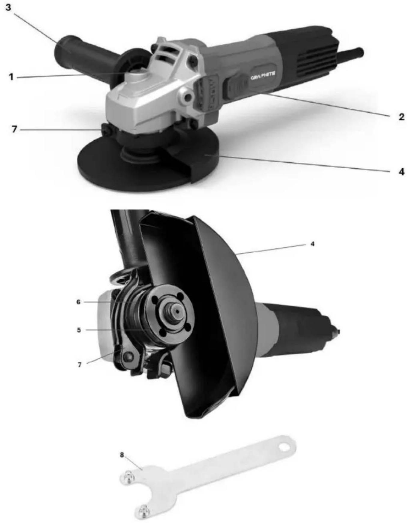

(PL) INSTRUKCJA OBSŁUGI ORYGINALNA....4
(EN) TRANSLATION OF THE ORIGINAL INSTRUCTIONS......8
(UA) ПЕРЕКЛАД ОРИГИНАЛЬНИХ ІНСТРУКЦІЙ.... 12
(RO) TRADUCEREA INSTRUCTIUNILOR ORIGINALE....16
(HU) AZ EREDETI UTASÍTÁSOK FORDÍTÁSA 20
(IT) TRADUZIONE DELLE ISTRUZIONI ORIGINALI....24
(FR) TRADUCTION DES INSTRUCTIONS ORIGINALES...... 28
(DE) ÜBERSETZUNG DER ORIGINALANLEITUNG .... 32
(RU) ПЕРЕВОД ОРИГИНАЛЬНЫХ ИНСТРУКЦИЙ ...... 36
(CZ) PŘEKLAD PŮVODNÍCH POKYNŮ......41
(SK) PREKLAD PÔVODNÝCH POKYNOV 45
(HR) PRIJEVOD IZVORNIH UPUTA 48
(LT) ORIGINALU INSTRUKCIJU VERTIMAS....52
(LV) ORIGINĀLO NORĀDĪJUMU TULKOJUMS...... 56
(SL) PREVAJANJE IZVIRNIH NAVODIL 60
(BG) ПРЕВОД НА ОРИГИНАЛНИТЕ ИНСТРУКЦИИ...... 63
(SR) ПРЕВОД ОРИГИНАЛНИХ УПУТСТАВА....68
(GR) METAΦΡΑΣΗ ΤΩΝ ΑΡΧΙΚΩΝ ΟΔΗΓΙΩΝ....72
(NL) VERTALING VAN DE ORIGINELE INSTRUCTIES......76
(PT) TRADUÇÃO DAS INSTRUÇÕES ORIGINAIS......80
(ES) TRADUCCIÓN DE LAS INSTRUCCIONES ORIGINALES.. 84
(EE) ORIGINAALJUHISTE TÖLGE 88
(PL) INSTRUKCJA OBSŁUGI ORYGINALNA
SZLIFIERKA KĄTOWA 58G184
CAUTION Read all safety warnings, instructions, illustrations and specifications provided with this power tool. Failure to follow all of the instructions below may result in electric shock, fire and/or serious injury.
Keep all warnings and instructions for future reference.
- This power tool is designed to be used as a grinder, polisher or cutter. Read all safety warnings, instructions, illustrations and specifications provided with this power tool. Failure to follow all of the instructions below may result in electric shock, fire and/or serious injury.
- Do not use this power tool for sanding, wire brushing or cutting holes. Operations for which the power tool is not designed may create hazards and cause personal injury.
- Do not modify this power tool in any way that is not expressly provided for and specified by the tool manufacturer. Such modification may result in loss of control and serious personal injury.
- Do not use accessories that are not specifically designed and specified by the tool manufacturer. The mere fact that an accessory fits the power tool does not guarantee safe operation.
- The rated speed of the accessory must be at least equal to the maximum speed specified on the power tool. Accessories operating at speeds higher than the rated speed may be damaged and break into pieces.
- The outer diameter and thickness of the accessory must be within the rated parameters of the power tool. Accessories with inappropriate dimensions cannot be properly secured or controlled.
- The mounting dimensions of the accessory must match the mounting dimensions of the power tool. Accessories that do not fit the mounting dimensions of the power tool will become unbalanced, vibrate excessively and may cause loss of control.
- Do not use damaged accessories. Before each use, check accessories such as grinding wheels for chips and cracks, grinding wheel pads for cracks, tears or excessive wear, and wire brushes for loose or broken wires. If the power tool or accessory has been dropped, check it for damage or install undamaged accessories. After checking and installing the accessory, ensure that the operator and bystanders are clear of the rotating accessory plane and run the power tool at maximum speed without load for one minute. Damaged accessories will usually fail during this test.
- Wear personal protective equipment. Depending on the application, use a face shield, safety glasses or safety goggles. If necessary, wear a dust mask, ear protection, gloves and a workshop apron to protect against small abrasive particles or fragments of the workpieces. Eye protection must be able to stop fragments generated during various applications. The dust mask or respirator must be capable of filtering the particles generated during the application. Prolonged exposure to high noise levels can cause hearing loss.
- Bystanders should keep a safe distance from the work area. Anyone entering the work area must wear personal protective equipment. Fragments of the workpiece or damaged equipment may fly off and cause injury outside the immediate work area.
- When performing operations where the cutting tool may come into contact with hidden wiring or its own cable, hold the power tool only by its insulated gripping surfaces. Contact between the cutting tool and a live wire may cause exposed metal parts of the power tool to become live, which may result in electric shock to the operator.
- Keep the cable away from the rotating part. If you lose control, the cable may be cut or snagged, and your hand or arm may be pulled into the rotating part.
- Never put down the power tool until the accessory has come to a complete stop. The rotating accessory may catch on the surface and pull the power tool out of your hands.
- Do not use the power tool while carrying it. Accidental contact with the rotating accessory may cause it to snag on clothing and pull the accessory towards the body.
- Clean the ventilation openings of the power tool regularly. The motor fan draws dust into the housing, and excessive accumulation of powdered metal can cause an electrical hazard.
- Do not use power tools near flammable materials. Sparks may ignite these materials.
- Do not use accessories that require liquid coolants. The use of water or other liquid coolants may result in electric shock or electric shock.
- Only use the types of discs specified for the power tool and guards designed for the selected discs. Discs for which the power tool is not designed may not be adequately protected and are dangerous.
- The grinding surface of wheels with a centre recess must be mounted below the plane of the guard edge. An incorrectly mounted wheel that protrudes beyond the plane of the guard edge cannot be adequately protected.
- The guard must be securely attached to the power tool and positioned for maximum safety, so that as little of the disc surface as possible is exposed towards the operator. The guard protects the operator from disc fragments, accidental contact with the disc and sparks that could ignite clothing.
- Discs may only be used for specific applications. For example: do not grind with the side of a cutting disc. Cutting abrasive discs are designed for peripheral grinding, and lateral forces applied to these discs may cause them to fracture.
- Always use undamaged flanges that are the correct size and shape for the selected disc. Proper disc flanges support the disc, thereby reducing the risk of breakage. Flanges for cutting discs may differ from flanges for grinding discs.
- Do not use worn discs intended for larger power tools. A disc intended for a larger power tool is not suitable for the higher speed of a smaller tool and may break.
- When using dual-purpose discs, always use a guard that is suitable for the task at hand. Failure to use the correct guard may result in it not providing the desired level of protection, which could lead to serious injury.
- Do not "jam" the cutting disc or apply excessive pressure. Do not attempt to make cuts that are too deep. Overloading the disc increases its load and susceptibility to twisting or jamming during cutting, as well as the risk of kickback or disc breakage.
- Do not position your body in line with the rotating blade or behind it. When the blade moves away from your body during operation, any kickback may cause the rotating blade and power tool to be thrown directly towards you.
- If the disc becomes jammed or cutting is interrupted for any reason, switch off the power tool and hold it steady until the disc comes to a complete stop. Never attempt to remove the cutting disc from the cutting area while the disc is in motion, as this may cause kickback. Investigate the cause of the disc jamming and take action to eliminate it.
- Do not resume cutting in the workpiece. Wait until the blade reaches full speed and then carefully resume cutting. If you resume operation of the power tool in the workpiece, the blade may jam, shift or kick back.
- Support panels or other oversized items to minimise the risk of blade jamming and kickback. Large items tend to sag under their own weight. Supports should be placed under the item near the cutting line and the edges of the item on both sides of the blade.
- Use extreme caution when making "pocket cuts" in existing walls or other blind areas. A protruding blade may cut through gas or water pipes, electrical wiring, or objects that could cause kickback.
- Do not attempt to make curved cuts. Excessive blade load increases pressure and susceptibility to blade twisting or jamming during cutting, and the risk of blade kickback or breakage, which can result in serious injury.
- Do not allow any loose parts of the polishing cap or its fastening cords to rotate freely. Tuck away or trim any loose fastening cords. Loose and rotating fastening cords can wrap around your fingers or catch on the workpiece.
• CAUSES AND PREVENTION OF OPERATOR KICKBACK:
- Kickback is a sudden reaction to jamming or snagging of a rotating wheel, pad, brush or other accessory. Jamming or snagging causes the rotating accessory to stop abruptly, which in turn causes the uncontrolled power tool to be pushed in the opposite direction of the accessory's rotation at the point of jamming.
- For example, if a grinding wheel becomes caught or jammed by the workpiece, the edge of the grinding wheel entering the point of jamming may dig into the surface of the material, causing the grinding wheel to jump or be thrown out. The grinding wheel may rebound towards or away from the operator, depending on the direction of movement of the grinding wheel at the moment of jamming. Under such conditions, grinding wheels may also fracture.
- Kickback is the result of improper use of the power tool and/or incorrect procedures or working conditions and can be avoided by taking the appropriate precautions listed below:
Hold the power tool firmly with both hands and position your body and arms so that you can counteract the force of kickback. Always use the auxiliary handle, if the tool has one, to gain maximum control over kickback or torque reaction during start-up. The operator can control torque reactions or kickback forces if the appropriate precautions are taken.
➢ Never place your hands near rotating accessories. Kickback may cause the accessory to rebound towards your hands.
Do not position your body in the area where the power tool will move in the event of kickback. Kickback will cause the tool to be thrown in the opposite direction to the wheel's movement at the point of contact.
Be particularly careful when working in corners, on sharp edges, etc. Avoid bouncing and snagging the accessory. Corners or sharp edges can cause the
accessory to snag or bounce, resulting in loss of control or kickback.
Do not fit a wood carving chain blade, a segmented diamond blade with a circumferential gap greater than 10 mm, or a toothed blade. These blades cause frequent kickback and loss of control.
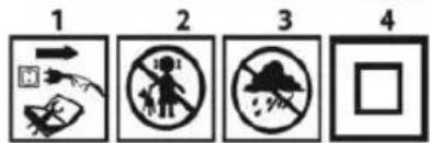
Explanation of pictograms used.


9
10
- Caution: take special precautions
- Read the operating instructions and observe the warnings and safety precautions contained therein!
- Use personal protective equipment (safety goggles, ear protectors, dust mask)
- Wear protective gloves
- Disconnect the power cord before performing any maintenance or repair work.
- Keep children away from the tool
- Protect from rain
- Protection class II
-
EAC certification mark.
-
Ukrainian market certification mark.
MARKINGS ON THE DEVICE

RRRR -year of manufacture
MM - month of manufacture
Y -additional designation
XXXXX -serial number
NNN -additional marking
DESIGN AND APPLICATION
An angle grinder is a hand-held power tool with class II insulation. The device is driven by a single-phase commutator motor, whose rotational speed is reduced by means of a toothed angular gear. It can be used for both grinding and cutting. This type of power tool is widely used for removing all types of burrs from the surfaces of metal elements, surface treatment of welds, cutting thin-walled pipes and small metal elements, etc. With the appropriate accessories, an angle grinder can be used not only for cutting and grinding, but also for cleaning, e.g. rust, paint coatings, etc.
Its areas of application include broadly understood repair and construction work, not only related to metals. An angle grinder can also be used for cutting and grinding building materials, e.g. bricks, paving stones, ceramic tiles, etc.
The device is intended for dry use only and is not suitable for polishing. Do not use the power tool for purposes other than those for which it is intended.
Improper use.
- Do not process materials containing asbestos. Asbestos is carcinogenic.
- Do not process materials whose dust is highly flammable or explosive. When working with power tools, sparks are generated which may ignite the vapours emitted.
- Do not use cutting discs for grinding work. Cutting discs work with their side surface, and grinding with the front surface of such a disc may damage it, resulting in personal injury to the operator.
DESCRIPTION OF GRAPHIC PAGES
The numbering below refers to the components of the device shown on the graphic pages of this manual.
-
Spindle lock button
-
Switch
-
Additional handle
-
Disc guard
-
Outer flange
-
Inner flange
-
Lever (blade guard)
-
Special key
* There may be differences between the drawing and the product.
ACCESSORIES
• Disc guard 1 pc.
• Special wrench 1
• Additional handle 1 pc.
PREPARATION FOR WORK
INSTALLATION OF ADDITIONAL HANDLE
The additional handle (3) is installed in one of the holes on the grinder head. It is recommended to use the grinder with the additional handle. If you hold the grinder with both hands during operation (also using the additional handle), there is less risk of touching the rotating disc or brush with your hand and suffering injury during recoil.
INSTALLATION AND ADJUSTMENT OF THE DISC GUARD
The disc guard protects the operator from debris, accidental contact with the working tool or sparks. It should always be fitted, taking extra care to ensure that the covering part faces the operator.
Mounting design mounting of the blade guard allows the guard to be adjusted to the optimum position without the use of tools.
- Loosen and pull back the lever (7) on the blade guard (4).
- Turn the blade guard (4) to the desired position.
- Lock by lowering the lever (7).
Removal and adjustment of the blade guard is carried out in the reverse order to its installation.
REPLACEMENT OF WORK TOOLS
Wear work gloves when replacing working tools.
The spindle lock button (1) is used only to lock the grinder spindle during installation or removal of the working tool. Do not use it as a brake button while the disc is spinning. Doing so may damage the grinder or injure the user.
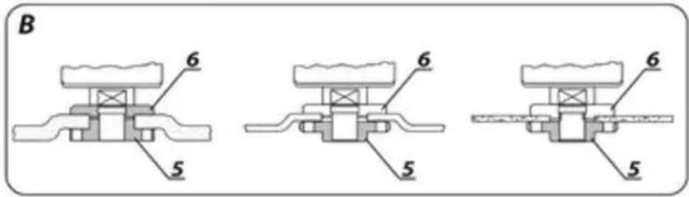
INSTALLING DISCS
For grinding or cutting discs with a thickness of less than 3 mm, the self-locking nut of the outer flange (5) must be screwed on with a flat surface on the disc side.
- Press the spindle lock button (1).
- Tighten the outer flange (5) with a special wrench (8).
- Loosen and remove the self-locking outer flange (5).
- Place the disc so that it is pressed against the surface of the inner flange (6).
- Screw on the outer flange (5) and tighten with a special wrench (8). The discs are removed in the reverse order to installation. During installation, the disc should be pressed against the surface of the inner flange (6) and centred on its chamfer. If the self-locking nut is stuck, use a special wrench.
INSTALLATION OF WORK TOOLS WITH A THREADED HOLE
- Press the spindle lock button (1).
-
Remove the previously mounted working tool, if any.
-
Before installation, remove both flanges – the inner flange (6) and the self-clamping outer flange (5).
- Screw the threaded part of the working tool onto the spindle and tighten it slightly.
The removal of working tools with a threaded hole is carried out in the reverse order to installation.
INSTALLATION OF AN ANGLE GRINDER IN AN ANGLE GRINDER STAND
It is permissible to use an angle grinder in a dedicated stand for angle grinders, provided that it is correctly installed in accordance with the stand manufacturer's installation instructions.
Before using the grinder, check the condition of the grinding wheel. Do not use chipped, cracked or otherwise damaged grinding wheels. Replace a worn disc or brush with a new one immediately before use. After finishing work, always switch off the grinder and wait until the working tool has come to a complete stop. Only then can the grinder be put away. Do not slow down the rotating grinding wheel by pressing it against the workpiece.
- Never overload the grinder. The weight of the power tool exerts sufficient pressure to work effectively. Overloading and excessive pressure can cause dangerous breakage of the working tool.
- If the grinder falls during operation, it is essential to check and, if necessary, replace the working tool if it is found to be damaged or deformed.
- Never strike the workpiece with the tool.
- Avoid bouncing the disc and scraping the material with it, especially when working on corners, sharp edges, etc. (this may cause loss of control of the power tool and kickback).
- Never use discs designed for cutting wood from circular saws. The use of such discs often results in kickback of the power tool, loss of control and may lead to injury to the operator.
TURNING ON/OFF
Hold the sander with both hands during start-up and operation. The sander is equipped with a safety switch to prevent accidental start-up.
- Press the switch button (2).
- Releasing the pressure on the switch button (2) stops the grinder.
After starting the grinder, wait until the grinding wheel reaches its maximum speed before starting work. Do not use the switch to turn the grinder on or off while working. The grinder switch may only be operated when the power tool is away from the workpiece.
CUTTING
- Cutting with an angle grinder may only be performed in a straight line.
- Do not cut material while holding it in your hand.
- Large pieces should be supported and care should be taken to ensure that the support points are close to the cutting line and at the end of the material. Material that is securely positioned will not tend to move during cutting.
- Small elements should be secured, e.g. in a vice, using clamps, etc. The material should be secured so that the cutting point is close to the securing element. This will ensure greater cutting precision.
- Do not allow the cutting disc to vibrate or bounce, as this will impair the quality of the cut and may cause the cutting disc to break.
- Do not apply lateral pressure to the cutting disc during cutting.
- Use the correct cutting disc for the type of material being cut.
- When cutting material, it is recommended that the feed direction be consistent with the direction of rotation of the cutting disc.
The cutting depth depends on the diameter of the blade.
- Only use discs with nominal diameters not exceeding those recommended for the specific grinder model.
- For deep cuts (e.g. profiles, building blocks, bricks, etc.), do not allow the mounting flanges to come into contact with the material being processed.
Cutting discs reach very high temperatures during operation – do not touch them with exposed parts of your body before they have cooled down.
GRINDING
For grinding work, you can use, for example, grinding discs, cup wheels, flap discs, discs with abrasive non-woven fabric, wire brushes, flexible discs for sandpaper, etc. Each type of disc and workpiece requires the appropriate working technique and the use of appropriate personal protective equipment.
Do not use discs intended for cutting for grinding.
Grinding discs are designed to remove material with the edge of the disc.
- Do not grind with the side surface of the disc. The optimum working angle for this type of disc is 30^ .
- Grinding work may only be carried out using grinding discs suitable for the type of material in question.
When working with flap discs, abrasive fibre discs and flexible discs for sandpaper, pay attention to the correct angle of attack.
- Do not grind with the entire surface of the disc.
• These types of discs are used for machining flat surfaces.
Wire brushes are mainly intended for cleaning profiles and hard-to-reach areas. They can be used to remove rust, paint coatings, etc. from the surface of the material.
Only use tools with a permissible rotational speed that is higher than or equal to the maximum speed of the angle grinder without load.
Before performing any installation, adjustment, repair or maintenance work, remove the power cord plug from the mains socket.
MAINTENANCE AND STORAGE
- It is recommended to clean the device immediately after each use.
- Do not use water or other liquids for cleaning.
- Clean the device with a dry cloth or blow it with low-pressure compressed air.
-
Do not use any cleaning agents or solvents as they may damage plastic parts.
-
Clean the ventilation slots in the motor housing regularly to prevent the device from overheating.
- If the power cord is damaged, replace it with a cord of the same specifications. This should be done by a qualified specialist or by taking the device to a service centre.
- Always store the device in a dry place out of the reach of children. Any faults should be repaired by an authorised service centre of the manufacturer.
TECHNICAL PARAMETERS
RATED DATA
| PARAMETER | VALUE |
| Supply voltage | 230 V AC |
| Power supply frequency | 50 Hz |
| Rated power | 950 W |
| Rated rotational speed | 3000–12000 min ^-1 |
| Max. blade diameter | 125 mm |
| Internal blade diameter | 22.2 mm |
| Spindle thread | M14 |
| Protection class | II |
| Weight | 2 kg |
| NOISE AND VIBRATION DATA | |
| Sound pressure level | L_PA = 92.23dB(A) K=3dB(A) |
| Sound power level | L_WA = 100.23dB(A) K=3dB(A) |
| Acceleration value | a_h = 12.723 m/s^2 K=1.5 m/s^2 |
NOISE AND VIBRATION DATA
Information on noise and vibration
The emitted noise levels, such as the emitted sound pressure level Lp_A and the sound power level Lw_A and the measurement uncertainty K, are given below in the manual in accordance with the standard EN 62841-1.
The vibration values (acceleration values) a_n and measurement uncertainty K are marked in accordance with EN 62841-1 and are given below.
The vibration level specified in this manual has been measured in accordance with the measurement procedure specified in EN 62841-1 and can be used to compare power tools. It can also be used for a preliminary assessment of vibration exposure.
The vibration level given is representative of the basic applications of the power tool. If the power tool is used for other applications or with other working tools, or if it is not sufficiently maintained, the vibration level may change. The reasons given above may increase exposure to vibration during the entire working period.
To accurately estimate vibration exposure, periods when the power tool is switched off or when it is switched on but not used for work must be taken into account. In this way, the total vibration exposure may be significantly lower.
Additional safety measures should be taken to protect the user from the effects of vibration, such as: maintenance of the power tool and working tools, ensuring adequate hand temperature, proper work organisation.
ENVIRONMENTAL PROTECTION

Electrically powered products should not be disposed of with household waste, but should be taken to appropriate facilities for disposal. Information on disposal can be obtained from the product retailer or local authorities. Used electrical and electronic equipment contains substances that are not environmentally neutral. Equipment that is not recycled poses a potential threat to the environment and human health.
"GTX Poland Spółka z ograniczoną odpowiedzialnością" Spółka komandytowa with its registered office in Warsaw, ul. Pograniczna 2/4 (hereinafter: "GTX Poland") hereby informs that all copyrights to the content of this manual (hereinafter: "Manual"), including, among others, its text, photographs, diagrams, drawings, as well as its composition, belong exclusively to GTX Poland and are protected by law in accordance with the Act of 4 February 1994 on copyright and related rights (i.e. Journal of Laws 2006 No. 90 Item 631, as amended). Copying, processing, publishing or modifying the entire Manual or any of its elements for commercial purposes without the written consent of GTX Poland is strictly prohibited and may result in civil and criminal liability.
EC Declaration of Conformity
Manufacturer: GTX Poland Sp. z o.o. Sp.k, Pograniczna Street 2/4 02-285 Warsaw
Product: Angle grinder
Model: 59G184
Trade name: GRAPHITE
Serial number: 00001 ÷ 99999
The product described above complies with the following documents:
Machinery Directive 2006/42/EC
Electromagnetic Compatibility Directive 2014/30/EU
RoHS Directive 2011/65/EU amended by Directive 2015/863/EU
And meets the requirements of the following standards:
EN IEC 62841-2-3:2021+A11; EN 62841-1:2015+A11
EN IEC 55014-1:2021; EN IEC 55014-2:2021; EN IEC 61000-3-
2:2019+A1; EN 61000-3-3:2013+A1+A2
EN IEC 63000:2018
This declaration applies only to the machine in the state in which it was placed on the market and does not cover components
added by the end user or subsequent actions carried out by them. Name and address of the person authorised to prepare the technical documentation who is resident or established in the EU:
Signed on behalf of:
GTX Poland Sp. Z o.o. Sp.k. Pograniczna Street 2/4
02-285 Warsaw

Paweł Kowalski
Technical Documentation Representative GTX Poland
Warsaw, 16 January 2024
Warsaw, 16 January 2024
(UA) ПЕРЕКЛАД ОРИГИНАЛЬНИХ ІНСТРУКЦІЙ КУТОВА ШЛІФУВАЛЬНА МАШИНА 58G184
CONCEPTION ET APPLICATION
MISE EN MARCHE/ARRÊT
DONNÉES RELATIVES AU BRUIT ET AUX VIBRATIONS
Directive Machines 2006/42/CE
5 6 7 8

9 10
INSTALLATIE VAN EXTRA HANDGREEP


- (PL) INSTRUKCJA OBSŁUGI ORYGINALNA
- SZLIFIERKA KĄTOWA 58G184
- MARKINGS ON THE DEVICE
- DESIGN AND APPLICATION
- Improper use.
- DESCRIPTION OF GRAPHIC PAGES
- ACCESSORIES
- PREPARATION FOR WORK
- INSTALLATION OF ADDITIONAL HANDLE
- INSTALLATION AND ADJUSTMENT OF THE DISC GUARD
- Mounting design mounting of the blade guard allows the guard to be adjusted to the optimum position without the use of tools.
- REPLACEMENT OF WORK TOOLS
- INSTALLING DISCS
- INSTALLATION OF WORK TOOLS WITH A THREADED HOLE
- INSTALLATION OF AN ANGLE GRINDER IN AN ANGLE GRINDER STAND
- TURNING ON/OFF
- CUTTING
- GRINDING
- MAINTENANCE AND STORAGE
- TECHNICAL PARAMETERS
- NOISE AND VIBRATION DATA
- Information on noise and vibration
- ENVIRONMENTAL PROTECTION
- EC Declaration of Conformity
- (UA) ПЕРЕКЛАД ОРИГИНАЛЬНИХ ІНСТРУКЦІЙ КУТОВА ШЛІФУВАЛЬНА МАШИНА 58G184
- CONCEPTION ET APPLICATION
- MISE EN MARCHE/ARRÊT
- DONNÉES RELATIVES AU BRUIT ET AUX VIBRATIONS
- Directive Machines 2006/42/CE
- 10
- INSTALLATIE VAN EXTRA HANDGREEP
Brand : Graphite
Model : 59G184
Category : Grinder